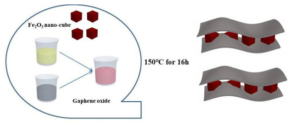
Scheme 1.
An illustration for the formation of Fe2O3/GH
High Rate Performance of Aqueous Magnesium-iron-ion Batteries Based on Fe2O3@GH as the Anode
Shuang-Xi SHAO , Rui-Bai CANG , Ke YE , Yin-Yi GAO , Kai ZHU , Jun YAN , Gui-Ling WANG , Dian-Xue CAO

Recently, magnesium ion battery has aroused more and more attention, in which not only the ion radius of magnesium is similar to that of lithium but also magnesium is low cost and abundant resources on the earth. Aqueous Mg-ion batteries (MIBs) attract much attention due to their high theoretical capacity and abundant resource[1]. The aqueous MIBs play an important role in the development of green energy compared with no-aqueous MIBs[2], because of their advantages of low cost, safety, stability, and sustainable development. The aqueous MIBs electrolyte comes from aqueous and inorganic magnesium salt. Since the first aqueous rechargeable battery was produced by SONY in 1994[3], most cathode materials such as MnO2, LiMn2O4 and Na0.44MnO2 have been used in lithium/sodium battery[4−8]. For the development of cathode materials, various cathode materials such as transition metal chalcogenides/oxides, polyanion compounds, and Prussian blue are synthesized as a capable host for Mg ion storage[9]. Among them, manganese oxide has become an interesting research subject and a capable host for MIBs owing to its high capacity (~200 mAh g−1), suitable working voltage and low cost[10−12]. In contrast, the progress in anode materials is slow and lack of capable anode materials, which seriously hinders the potential applications of aqueous MIBs[13−16]. Zhang et al. reported FeVO4 nanomaterials as anodes for aqueous MIBs with a capacity of 140 mAh g−1[17]. Unfortunately, their low capacity is difficult to match with manganese oxide cathode well and the structural collapse of pure materials results in a continuous capacity decay during the Mg (de)intercalation process. Thus, there is a challenge to identify an inexpensive anode with a large capacity and highly reversible charge storage mechanism in an aqueous electrolyte[18−20]. The controlled morphology of materials can effectively improve the electrochemical properties of materials. Nano Fe2O3 materials with special cubic structures because of its high theoretical capacity are used as an anode material having excellent properties (924 mAh g−1), low cost, low toxicity and natural abundance of iron[21−23]. Unfortunately, lithiation large volume expansion, poor electronic conductivity and ion diffusion capacity are major problems limiting the practical applicability of these negative electrode materials[24, 25].
According to the reports, the design and manufacture of particles have a special form and customized performance that can be enhanced by cycling performance and rate capability. The Fe2O3-based anode materials were used in the non-aqueous battery, because iron metal batteries are extremely competitive in their cost and iron possesses an attractive electrochemical property. Via the two-electron transfer, iron theoretically delivers a high specific capacity of ~960 mAh g−1 and an outstanding volumetric capacity of ~7557 mAh cm−3, both of which are higher than those for other electrode materials like P2-Mg1/3Ni1/3Mn2/3O2 electrode at 1.0 C in 1.0 M MgSO4 (101.4 mAh g−1), Mg(NO3)2 (99.7 mAh g−1), and MgCl2 (117.0 mAh g−1) electrolytes and NaTi(PO4)3 as an anode at 0.78 C in 1.0 M NaNO3 electrolyte (121 mAh g−1)[26, 27]. However, when the Fe2O3-based materials were used as anode or Fe2O3 as a cathode in aqueous MIBs, the magnesium ion can't insert/(de)insert in Fe2O3 but can only stick to Fe2O3. The above-mentioned iron-base anode materials show considerable interests on the Fe-metal flow batteries, where the cathode and anode operate on the Fe3+/Fe2+ and Fe2+/Fe3+ redox couples, respectively. Herein, we prepared the Fe2O3 and Fe2O3/graphene hydrogels (GH) anodes. The Fe2O3/GH displayed a capacity of 198 mAh g−1 in the aqueous MgSO4 + FeSO4 electrolyte for Mg-Fe ion battery, indicating an excellent storage capacity of magnesium and iron ions. All the above clearly reveal that Fe2O3/GH is an excellent anode material for high-performance Mg-Fe-ion battery and an important step in the development of an aqueous Mg-Fe-ion battery. This battery shows higher rate properties than other aqueous batteries[28−30], delivering the reversible capacity of 198 mAh g−1 at a current density of 50 mA g−1. This result also lays theoretical foundation for the application of aqueous magnesium-iron ion batteries.
The typical synthesis of FeCl3·6H2O was dissolved in ethanol and DI water under vigorously magnetic stirring, during which sodium acetate was added until complete dissolution. Then, the mixture was sealed in a Teflon-lined stainless-steel autoclave and maintained at 180 ℃ for 12 h. After cooling to room temperature, the products were formed as red solation and washed several times by DI water and ethanol, and the final dark red products were dried at 60 ℃ for overnight. Subsequently, the obtained Fe2O3/GH was utilized for fabricating Fe2O3/GH composite. The process of recombination of Fe2O3 and graphene composite is as follows. Firstly, for the preparation of solution A, graphene oxide was dissolved in DI-water and added into ethylenediamine with good stirring and even distribution. Secondly, Fe2O3 nanocubes were dissolved in DI-water to form solution B. Thirdly, solutions A and B were mixed and fully ultrasonicated to make the Fe2O3 nano-cubes uniformly disperse in the mixed solution (Scheme 1). Such a self-assembled composite is advantageous in the cubic structure of Fe2O3 nanoparticles and graphene can keep its original topography. Furthermore, it is noted that, after a hydrothermal reaction by freeze-drying procedures. The microstructure of composite can be easily controlled by graphene oxide, because the graphene sheet with a high surface area can effectively prevent the aggregation of Fe2O3 nanocube. Furthermore, the addition of Fe2O3 can effectively prevent the accumulation of graphene sheets, which can obtain the composite material with a high surface area. Meantime, the Fe2O3/GH nano-cubes composite with loose porous structure by freeze-drying process can enhance pore volume. Fe2O3/GH composite material having a high surface area and high electrical conductivity is a promising electrode material, so it can provide a large surface area of electrochemical reaction and discharging/charging process to provide several active Mg and Fe ion diffusions.
The slurry of the anode was constituted by mixing 10% polyvinylidene difluoride (PVDF) binder, 10% acetylene black and 80% Fe2O3 and Fe2O3/GH. The carbon fiber cloth with a size of 1.2 cm × 1.2 cm is used to coat the above slurry under vacuum drying at 80 ℃ for 24 h.
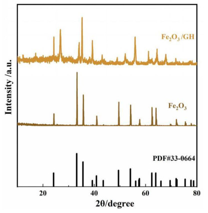
X-ray diffraction (XRD) gives the institute composite phase structure and phase purity (Fig. 1). The major diffraction peaks of Fe2O3 (brown line) and Fe2O3/GH (ginger line) can be well indexed to the phase of Fe2O3 (hematite, JCPDS33-0664). Comparing these two curves, the contrast between Fe2O3/GH and Fe2O3 shows a new peak at about 26.6, which is from graphene[31]. This result proves that Fe2O3/graphene hydrogel (GH) successfully recombines.
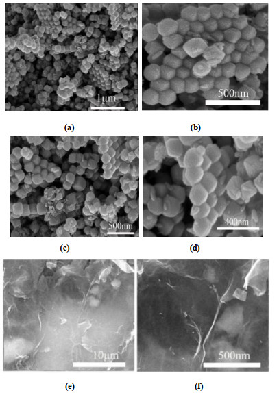
It has come to light that graphene is an electrode material with high conductivity and large specific surface area. Therefore, we prepared the Fe2O3 and graphene composite using as an anode to improve the electrochemical properties. Fig. 2 shows the SEM images of Fe2O3 and Fe2O3/GH. In Figs. 2a and 2b, Fe2O3 is the regular cube material. In Figs. 2c and 2d, the Fe2O3 anode materials demonstrate an average size less than 100 nm. Figs. 2e and 2f show the Fe2O3/GH image. A graphene sheet structure is clearly visible and the Fe2O3 is non-uniformly distributed on the sheet.
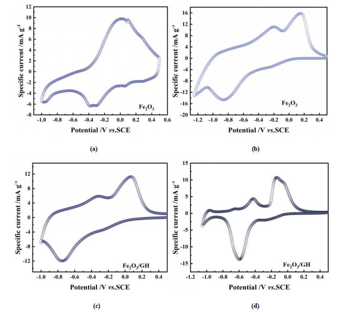
Fe2O3 and Fe2O3/GH are used as an anode material in 0.5 M MgSO4 and 0.5 M MgSO4 + FeSO4 aqueous electrolyte for the working electrode. The cyclic voltammetry (CV) curves of Fe2O3 and Fe2O3/GH electrodes with a voltage window of –1.1~0.5 V at a scan rate of 3.0 mV s–1 are shown in Fig. 3. Fig. 3a displays the Fe2O3 as an anode in 0.5 M MgSO4 aqueous solution, showing a cathodic peak at 0.0 V and three anodic peaks at –0.38, –0.30 and 0.08 V, respectively. In the CV curves, Mg ion is inserted in the electrode material, but Mg ion can't insert/(de)insert in the Fe2O3 nano-cube material during charge and discharge process. Fig. 3b shows the Fe2O3 anode materials in 0.5 M MgSO4 + FeSO4 aqueous solution, which has only two cathodic peaks at 0.26/–0.18 V and an anodic peak at –0.86 V. The whole peak-current potential shifts to the left direction with an obvious planning phenomenon. To further solve the above problems, the Fe2O3/GH was used as an anode in 0.5 M MgSO4 (Fig. 3c), which had two cathodic peaks at 0.15/–0.30 V and an anodic peak at –0.78 V with the polarization phenomenon disappearing significantly. The anode is still a quasi-reversible process, because Mg ion is only inserted at the Fe2O3 material in discharge. During charging, the Mg ions can't be released from the Fe2O3 material to form an irreversible state. Fig. 3d shows the Fe2O3/GH as an anode in MgSO4 + FeSO4 with a reversible system, which has two anodic peaks at –0.6/–0.3 V and cathodic peaks at –0.16/–0.46 V with potentials in safe voltage ranges. The insertion/(de)insertion process of Mg and Fe ions into/from Fe2O3/GH material results from the donor and acceptor of electrons accompanied with Mg2+ ion insertion/(de)insertion process into/from the lattice of Fe2O3/GH, in which the catholyte and anolyte operate on Fe2+/Fe3+ with the multi-step Mg/Fe-ion storage process. Electrochemical kinetics of the reaction at particular electrode can be determined from the voltage difference between the redox peaks. The Fe2O3 was used as an anode in MgSO4 and MgSO4 + FeSO4 aqueous solution, and the voltage gaps between the redox peaks are 0.51 and 0.81 V, respectively. For Fe2O3/GH as an anode in MgSO4 and MgSO4 + FeSO4 aqueous solution, the voltage gaps between the redox peaks are 0.72 and 0.51 V, respectively. Thus, the Fe2O3/GH in MgSO4 + FeSO4 decreased the electrode polarization, which is advantageous for the electrochemical reaction. Meanwhile, the Fe2O3/GH anode materials in MgSO4 + FeSO4 reveal preferable electrochemical properties than other electrodes according to the peak currents.
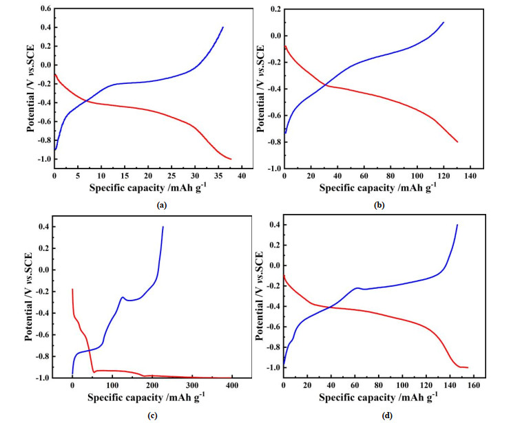
To further study the electrochemical properties of Fe2O3 and Fe2O3/GH, the galvanostatic charge-discharge measurements were tested in the voltage window of –1.0 to 0.4 V. Fig. 4a shows the Fe2O3 as an anode at 100 mA g–1 with the initial cycle discharge specific capacity of 38 mAh g–1 in 0.5 M MgSO4 and the coulombic efficiency close to 100%. In addition, Fe2O3 was used as anode within the voltage window of –0.85 to 0.1 V in MgSO4 + FeSO4 at 100 mA g–1 and its discharge specific capacity was 131 mAh g–1 (Fig. 4b). Although there is a certain improvement in specific capacity, the coulombic efficiency is weak with 91%. The discharge/charge curves of Fe2O3/GH as an anode in MgSO4 with the capacity of 400 mAh g-1 and coulombic efficiency of 62.5% are shown in Fig. 4c. After improving the conductivity of the electrode, the capacity is increased and verified before CV test. Mg ion is only inserted in the Fe2O3 material in discharge. During the charging process, Mg ion can't be released from the iron material to form an irreversible state. When the Fe2O3/GH was used as an anode in MgSO4 + FeSO4, it had an outstanding performance with the discharge specific capacity of 155 mAh g–1 and coulombic efficiency close to 100% at a current density of 100 mA g–1. Meanwhile, the potential of the discharge plateau is almost identical to that of CV. The Fe2O3/GH as an anode in 0.5 M MgSO4 + FeSO4 aqueous solution can not only avoid the phenomenon of hydrogen and oxygen evolution but also improve the electrochemical performance and stability to a certain extent.
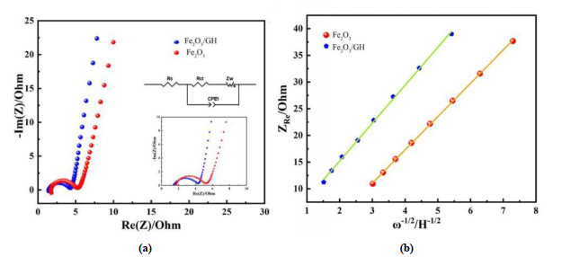
Electrochemical impedance spectroscopic (EIS) measurement of Fe2O3 and Fe2O3/GH in MgSO4 + FeSO4 is shown in Fig. 5. The main purpose of the EIS test is to further verify the diffusion rate of the Fe2O3 and Fe2O3/GH material in the electrolyte at room temperature. Fig. 5a shows the impedance spectra of Fe2O3 and Fe2O3/GH electrodes. In the high-frequency region, the partial semicircle indicates a charge transfer resistance (Rct) and the intercept indicates the internal resistance (Rs). In low-frequency region, the linear portion represents the Warburg impedance, which is utilized to determine the diffusion coefficient of magnesium-iron ions in the electrode. Therefore, the model circuit (inset of Fig. 5a) is fitted by ZView software and the relevant parameters are listed in Table 1. Fig. 5b shows the curve of ZRe as a function of ω−1/2, depending on the slope of linear portion of the low-frequency region. Therefore, the magnesium-iron ion diffusion coefficient (DMg2+) can be obtained by Eqs. (1) and (2) as below:
|
|
(1) |
|
|
(2) |
 DownLoad:
CSV
DownLoad:
CSV
| Sample | Rs (Ω) | DMg2+ (cm2 s−1) ± 0.01 E−15 | CPE-T | CPE-P | Sample | ||
| Fe2O3 | 3.52 | 8.88 E−15 | 9.23 E−5 | 0.98 | Fe2O3 | ||
| Fe2O3/GH | 3.16 | 9.65 E−15 | 9.77 E−5 | 0.90 | Fe2O3/GH |
where DMg2+ is the magnesium-iron ion diffusion coefficient (cm2 s−1), F is the Faraday constant, R is the gas constant, T is the room temperature (25 ℃), A is the surface area of the electrode, n is the number of transferred electrons (n = 1), σ is the slope of ZRe against ω−1/2 plot, and C is the concentration of the magnesium-iron ion.
In Table 1, the internal resistance Rs values of the two electrodes are a little different. The charge-transfer resistance Rct value of Fe2O3/GH is much smaller than that of the Fe2O3 electrode, because the Fe2O3/GH composite owns a larger specific surface area and higher electrical conductivity derived from the GH property and more beneficial for the charging process. ZRe is derived from Eq. (2) and the diffusion coefficient DMg2+ can be calculated from Eq. (1). The DMg2+ value of Fe2O3/GH electrode is much larger than that of the Fe2O3 electrode, proving that magnesium-iron ions diffuse faster onto the surface of electrode. In consequence, Rs and Rct of the Fe2O3/GH electrode shows a smaller value. The large DMg2+ value indicates a good electrochemical kinetics.
The Fe2O3/GH anode displays a high rate capability and superior cycle ability. Fig. 6 shows the Fe2O3/GH electrode charge/discharges in the potential region from –1.0 to 0.4 V at different currents in MgSO4 + FeSO4 electrolyte. Fig. 6a depicts the rate performance of Fe2O3/GH as an anode. The Fe2O3/GH exhibits the capacities of 198, 155, 121, 80, 75 and 27 mAh g–1 at 50, 100, 200, 300, 500 and 1000 mA g–1, respectively. All the discharge curves in Mg-Fe ion electrolyte exhibit a large potential plateau at around –0.4 and –0.6 V, which are associated with the insertion of Mg2+ into the lattice of Fe2O3/GH and the process of Fe3+ to Fe2+. The charge potential plateau appears at around –0.2 and 0.1 V, which are associated with the (de)insertion of Mg2+ from the lattice of Fe2O3/GH and process of Fe2+ to Fe3+, demonstrating a capable rate performance of Fe2O3/GH as an anode in 0.5 M MgSO4 + FeSO4 aqueous solution. Meanwhile, at a current density of 100 mA g–1, Fe2O3/GH anode exhibits a discharge specific capacity of 165 mAh g–1 at the initial cycle with a capacity retention of 89.3% after 200 cycles, suggesting an outstanding cycling stability (Fig. 6c). It is noted that, after 200 cycles, the respective capacity retention is close to 100%, demonstrating the most excellent cycle stability in MgSO4 + FeSO4 aqueous solution. The Mg-Fe ions are converted into the insertion without structural collapse with a reversible process. The electrochemical performance is prior to that of other aqueous-based batteries, such as 150 mAh g–1 of Mg-bir/CC in 0.5 M Mg(ClO4)2[31], 90 mAh g–1 of 400-MgMn2O4 in 3.0 M Mg(NO3)2[32], 51 mAh g–1 of CuFe-PBA in 1.0 M Mg(NO3)2[33] and 59.2 mAh g–1 of polypyrrole (PPy)-coated MoO3[34], which provides a new member for aqueous battery family (as listed in Table 2 and Table S1)[34–38].
 DownLoad:
CSV
DownLoad:
CSV
| Electrode | Electrolyte | Capacity (mAh g–1) | Ref. |
| TiO2 | Aqueous | 75 | 12 |
| Mg-bir/CC | Mg(ClO4)2 | 150 | 31 |
| Na3V2(PO4)3 | NaNO3 | 112 | 36 |
| (PPy)-coated/MoO3 | Aqueous | 59 | 34 |
| TiO2/graphene | Aqueous | 30 | 35 |
| 400-MgMn2O4 | Mg(NO3)2 | 90 | 32 |
| CuFe-PBA | Mg(NO3)2 | 51 | 33 |
| Na2Ti(PO4)3 | NaNO3 | 121 | 27 |
| V2O5/GA | MgSO4 | 75 | 21 |
| FeVO4 | MgSO4 | 118 | 17 |
| Fe2O3/GH | MgSO4 + FeSO4 | 198 | This work |
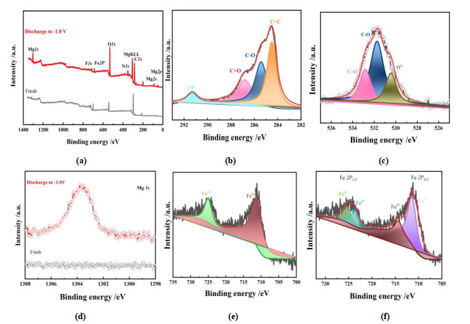
In order to further determine the composition of the composite material and electrochemical reaction changes, XPS measurement is performed to explore the change of magnesium-iron ions during the charging and discharging process of Fe2O3/GH electrode. Fig. 7a shows the survey spectra of Fe2O3/GH electrodes of fresh (black line) and discharge to –1.0 V (red line). It was clearly observed that Mg 1s, Mg 2s, and Mg 2p are discovered in the discharge to –1.0 V, and the F 1s peak comes from PVDF and C 1s peak from acetylene black and graphene. Fig. 7b depicts the C1s XPS spectra can be divided into four peaks, centered at 284.0, 285.4, 288.3 and 291.8 eV, respectively. They are consistent with the references of C=C, C–O, sp2-bonded C atoms and CF. The corresponding fraction of C=C bonding was almost the highest, revealing a deep deoxidation of graphene oxide. The CF comes from PVDF. As shown in Fig. 7c, the characteristic peaks in O 1s XPS spectra can be divided into three peaks. The peak at a binding energy of 529.0 eV represents an anion O2– for Fe2O3 in the center. Another peak at 531.2 eV indicates the presence of non-hydroxyl equivalent (or chemically adsorbed water) and Fe2O3 on the surface of the oxygen ion in the anoxic zone, and the third peak at 532.8 eV is corresponding to C=O in GH. Fig. 7d shows the Mg 1s peak is located at 1303 eV for the reduced electrode that discharges to –1.0 V. It is proved that a large number of Mg2+ ions are inserted into the lattice of the Fe2O3/GH electrode after the discharge process. In Fig. 7e, the electrode was observed in fresh Fe 2p XPS spectra with two peaks at 725.4 and 711.4 eV. This electrode is not inserted into Fe2O3/GH for magnesium ions[17, 36] and in good agreement with the formation of Fe2O3. When the electrode discharges to –1.0 V, the weak Fe 2p3/2 and Fe 2p1/2 peaks at 719.0 eV correspond to the characteristic peaks and their shake-up satellite peak of Fe 2p, respectively.
In this work, we introduced an anodic electrode of Fe2O3 in aqueous MIBs and recombined it with graphene hydrogels (GH) to form Fe2O3/GH. The Fe2O3 and Fe2O3/GH were electrochemically measured in different aqueous solutions. The Fe2O3 and Fe2O3/GH electrodes have overcome some problems such as the conservation of cycle stability and efficiency. The Fe2O3/GH as anode exhibits a high specific rate capacity and rate ability in 0.5 M MgSO4 + FeSO4. The charge/discharge specific capacity approaches to 86% capacity retention after 200 cycles, and the Fe2O3/GH electrode delivers a reversible capacity of 155 mAh g–1 at 100 mA g–1 with the coulombic efficiency close to 100%. Even at a high current density of 1000 mA g–1, all electrochemical platforms remain unchanged, and the discharge specific capacity is 25 mAh g–1. This material has not only a long cycle characteristic but also stable Coulomb efficiency, thus playing an important role in the construction of our green energy. For fixed or grid-level energy storage applications, it would be a viable alternative.
Whitacre, J. F.; Wiley, T.; Shanbhag, S.; Wenzhuo, Y.; Mohamed, A.; Chun, S. E.; Weber, E.; Blackwood, D.; Lynch-Bell, E.; Gulakowski, J.; Smith, C.; Humphreys, D. An aqueous electrolyte, sodium ion functional, large format energy storage device for stationary applications. J. Power Sources 2012, 213, 255–264. doi: 10.1016/j.jpowsour.2012.04.018
Pang, G.; Yuan, C.; Nie, P.; Ding, B.; Zhu, J.; Zhang, X. Synthesis of NASICON-type structured NaTi2(PO4)3-graphene nanocomposite as an anode for aqueous rechargeable Na-ion batteries. Nanoscale 2014, 6, 6328–6334. doi: 10.1039/C3NR06730K
Ferg, E.; Gummow, R.; De, K. A. Spinel anodes for lithium-ion batteries. J. Electrochem. Soc. 1994, 141, L147–L150. doi: 10.1149/1.2059324
Sauvage, F.; Baudrin, E.; Tarascon, J. M. Study of the potentiometric response towards sodium ions of Na0.44-xMnO2 for the development of selective sodium ion sensors. Sensor. Actuat. B: Chem. 2007, 120, 638–644. doi: 10.1016/j.snb.2006.03.024
An, Y.; Tian, Y.; Wei, C.; Jiang, H.; Xi, B.; Xiong, S.; Feng, J.; Qian, Y. Scalable and physical synthesis of 2D silicon from bulk layered alloy for lithium-ion batteries and lithium-metal batteries. ACS Nano 2019, 13, 13690–13701. doi: 10.1021/acsnano.9b06653
Li, Z.; Young, D.; Xiang, K.; Carter, W. C.; Chiang, Y. M. Towards high power high energy aqueous sodium-ion batteries: the NaTi2(PO4)3/Na0.44MnO2 system. Adv. Energy Mater. 2013, 3, 290–294. doi: 10.1002/aenm.201200598
Song, W.; Ji, X.; Zhu, Y.; Zhu, H.; Li, F.; Chen, J.; Lu, F.; Yao, Y.; Banks C. E. Aqueous sodium-ion battery using a Na3V2(PO4)3 electrode. ChemElectroChem. 2014, 1, 871–876. doi: 10.1002/celc.201300248
Yuan, C.; Zhang, Y.; Pan, Y.; Wang, G.; Cao, D. Investigation of the intercalation of polyvalent cations (Mg2+, Zn2+) into λ-MnO2 for rechargeable aqueous battery. Electrochim. Acta 2014, 116, 404–412. doi: 10.1016/j.electacta.2013.11.090
Wang, X.; Bommier, C.; Jian, Z.; Li, Z.; Chandrabose, R. S.; Rodriguez-Perez, I. A.; Greaney, P. A.; Ji, X. Hydronium-ion batteries with perylenetetracarboxylic dianhydride crystals as an electrode. Angew. Chem. Int. Ed. 2017, 56, 2909–2913. doi: 10.1002/anie.201700148
Zhu, C.; Han, T.; Duoss, E. B.; Golobic, A. M.; Kuntz, J. D.; Spadaccini, C. M.; Worsley, M. A. Highly compressible 3D periodic graphene aerogel microlattices. Nat. Commun. 2015, 6, 1–8.
Alfaruqi, M. H.; Mathew, V.; Gim, J.; Kim, S.; Song, J.; Baboo, J. P.; Sun, H. C.; Kim, J. Electrochemically induced structural transformation in a γ-MnO2 cathode of a high capacity zinc-ion battery system. Chem. Mater. 2015, 27, 3609–3620. doi: 10.1021/cm504717p
Sha, L.; Liu, T.; Ye, K.; Zhu, K.; Yan, J.; Yin, J.; Wang, G.; Cao, D. A heterogeneous interface on NiS@Ni3S2/NiMoO4 heterostructures for efficient urea electrolysis. J. Mater. Chem. A 2020, 8, 18055–18063. doi: 10.1039/D0TA04944A
Luo, W.; Allen, M.; Raju, V.; Ji, X. An organic pigment as a high-performance cathode for sodium-ion batteries. Adv. Energy Mater. 2014, 4, 554–559.
Li, D.; Guo, W.; Li, Y.; Tang, Y.; Yan, J.; Meng, X.; Xia, M.; Gao, F.; Tunnel structured hollandite K0.06TiO2 microrods as the negative electrode for 2.4 V flexible all-solid-state asymmetric supercapacitors with high performance. J. Power Sources 2019, 413, 34–41. doi: 10.1016/j.jpowsour.2018.11.088
Bančič, T.; Bitenc, J.; Pirnat, K.; Kopač, L. A.; Grdadolnik, J.; Randon, V. A.; Dominko, R. Electrochemical performance and redox mechanism of naphthalene-hydrazine diimide polymer as a cathode in magnesium battery. J. Power Sources 2018, 395, 25–30. doi: 10.1016/j.jpowsour.2018.05.051
Ye, K.; Cao, A.; Shao, J.; Wang, G.; Si, R.; Ta, N.; Xiao, J.; Wang, G. Synergy effects on Sn–Cu alloy catalyst for efficient CO2 electroreduction to formate with high mass activity. Sci. Bull. 2020, 65, 711–719. doi: 10.1016/j.scib.2020.01.020
Cang, R.; Ye, K.; Shao, S.; Zhu, K.; Yan, J.; Wang, G.; Cao, D. A new perylene-based tetracarboxylate as anode and LiMn2O4 as cathode in aqueous Mg–Li batteries with excellent capacity. Chem. Eng. J. 2021, 405, 126783–126791. doi: 10.1016/j.cej.2020.126783
Chen, L.; Bao, J. L.; Dong, X.; Truhlar, D. G.; Wang, Y.; Wang, C.; Xia, Y. Aqueous Mg-ion battery based on polyimide anode and Prussian blue cathode. ACS Energy Lett. 2017, 2, 1115–1121. doi: 10.1021/acsenergylett.7b00040
Bitenc, J.; Pirnat, K.; Mali, G.; Novosel, B.; Vitanova, A. R.; Dominko, R. Poly(hydroquinoyl-benzoquinonyl sulfide) as an active material in Mg and Li organic batteries. Electrochem. Commun. 2016, 69, 1–5. doi: 10.1016/j.elecom.2016.05.009
Dong, X.; Guo, Z.; Guo, Z.; Wang, Y.; Xia, Y. Organic batteries operated at −70 ℃. Joule 2018, 2, 902–913. doi: 10.1016/j.joule.2018.01.017
Zhang, H.; Ye, K.; Zhu, K.; Cang, R.; Yan, J.; Cheng, K.; Wang, G.; Cao, D. High-energy-density aqueous magnesium-ion battery based on a carbon-coated FeVO4 anode and a Mg-OMS-1 cathode. Chem. Eur. J. 2017, 23, 17118–17126. doi: 10.1002/chem.201703806
Ye, K.; Zhou, Z.; Shao, J.; Lin, L.; Gao, D.; Ta, N.; Si, R.; Wang, G.; Bao, X. In situ reconstruction of a hierarchical Sn–Cu/SnOx core/shell catalyst for high-performance CO2 electroreduction. Angew. Chem. Int. Ed. 2020, 59, 4814–4821. doi: 10.1002/anie.201916538
Wang, F.; Fan, X.; Gao, T.; Sun, W.; Ma, Z.; Yang, C.; Han, F.; Xu, K.; Wang, C. High-voltage aqueous magnesium ion batteries. ACS Central Sci. 2017, 3, 1121–1128. doi: 10.1021/acscentsci.7b00361
Tang, Y.; Chen, T.; Yu, S.; Qiao, Y.; Mu, S.; Hu, J.; Gao, F. Synthesis of graphene oxide anchored porous manganese sulfide nanocrystals via the nanoscale Kirkendall effect for supercapacitors. J. Mater. Chem. A 2015, 3, 12913–12919. doi: 10.1039/C5TA02480C
Wang, Y.; Cui, X.; Zhang, Y.; Zhang, L.; Gong, X.; Zheng, G. Energy storage: achieving high aqueous energy storage via hydrogen-generation passivation. Adv. Mater. 2016, 28, 7626–7632. doi: 10.1002/adma.201602583
Cang, R.; Ye, K.; Zhu, K.; Yan, J.; Yin, J.; Cheng, K.; Wang, G.; Cao, D. Organic 3D interconnected graphene aerogel as cathode materials for high-performance aqueous zinc ion battery. J. Energy Chem. 2020, 45, 52–58. doi: 10.1016/j.jechem.2019.09.026
Sha, L.; Ye, K.; Yin, J.; Zhu, K.; Cheng, K.; Yan, J.; Wang, G.; Cao, D. In situ grown 3D hierarchical MnCo2O4.5@Ni(OH)2 nanosheet arrays on Ni foam for efficient electrocatalytic urea oxidation. Chem. Eng. J. 2020, 381, 122603–122611. doi: 10.1016/j.cej.2019.122603
Kundu, D.; Oberholzer, P.; Glaros, C.; Bouzid, A.; Tervoort, E.; Pasquarello, A.; Niederberger, M. An organic cathode for aqueous Zn-ion batteries: taming a unique phase evolution toward stable electrochemical cycling. Chem. Mater. 2018, 30, 13–17.
Sha, L.; Ye, K.; Wang, G.; Shao, J.; Zhu, K.; Cheng, K.; Yan, J.; Wang, G.; Cao, D. Rational design of NiCo2S4 nanowire arrays on nickel foam as highly efficient and durable electrocatalysts toward urea electrooxidation. Chem. Eng. J. 2019, 359, 1652–1658. doi: 10.1016/j.cej.2018.10.225
Cang, R.; Zhao, C.; Ye, K.; Yin, J.; Zhu, K.; Yan, J.; Wang, G.; Cao, D. Aqueous calcium-ion battery based on a mesoporous organic anode and a manganite cathode with long cycling performance. ChemSusChem. 2020, 13, 3911–3918. doi: 10.1002/cssc.202000812
Rodríguez-Pérez, I. A.; Yuan, Y.; Bommier, C.; Wang, X.; Ma, L.; Leonard, D. P.; Lerner, M. M.; Carter, R. G.; Wu, T.; Greaney, A.; Lu, J.; Ji, X. Mg-ion battery electrode: an organic solid's herring bone structure squeezed upon Mg-ion insertion. J. Am. Chem. Soc. 2017, 139, 313–322.
Walter, M.; Kravchyk, K. V.; Bofer, C.; Widmer, R.; Kovalenko, M. V. Polypyrenes as high-performance cathode materials for aluminum batteries. Adv. Mater. 2018, 30, 1705644–1705650. doi: 10.1002/adma.201705644
Xie, J.; Rui, X.; Gu, P.; Wu, J.; Xu, Z.; Yan, Q.; Zhang, Q. Novel conjugated ladder-structured oligomer anode with high lithium storage and long cycling capability. ACS Appl. Mater. Inter. 2016, 8, 16932–16938. doi: 10.1021/acsami.6b04277
Zhao, Q.; Lu, Y.; Chen, J. Advanced organic electrode materials for rechargeable sodium-ion batteries. Adv. Energy Mater. 2017, 7, 1601792–1601814. doi: 10.1002/aenm.201601792
Sun, X.; Duffort, V.; Mehdi, B. L. Investigation of the mechanism of Mg insertion in birnessite in nonaqueous and aqueous rechargeable mg-ion batteries. Chem. Mater. 2016, 28, 534–542. doi: 10.1021/acs.chemmater.5b03983
Mizuno, Y.; Okubo, M.; Hosono, E.; Kudo, T.; Ohishi, K.; Okazawa, A.; Kojima, N.; Kurono, R.; Nishimura, S.; Yamada, A. Electrochemical Mg2+ intercalation into a bimetallic CuFe prussian blue analog in aqueous electrolytes. J. Mater. Chem. A 2013, 1, 13055–13059. doi: 10.1039/c3ta13205f
Pan, B.; Huang, J.; Feng, Z.; Li, Z.; He, M.; Zhang, L.; Vaughey, J. T.; Bedzyk, M. J.; Fenter, P.; Zhang, Z.; Burrell, A. K.; Liao, C. Polyanthraquinone-based organic cathode for high-performance rechargeable magnesium-ion batteries. Adv. Energy Mater. 2016, 6, 1600140–1600146. doi: 10.1002/aenm.201600140
Liu, S.; Pan, G. L.; Yan, N. F.; Gao, X. P. Aqueous TiO2/Ni(OH)2 rechargeable battery with a high voltage based on proton and lithium insertion/extraction reactions. Energy Environ. Sci. 2010, 3, 1732–1735. doi: 10.1039/c0ee00170h

Figure 3 CVs of Fe2O3 electrode in 0.5 M MgSO4 (a) and 0.5 M MgSO4 + FeSO4 (b) electrolyte, respectively; Fe2O3/GH electrode in 0.5 M MgSO4 (c) and 0.5 M MgSO4 + FeSO4 (d) electrolyte, respectively

Figure 4 Galvanostatic charge and discharge curves of Fe2O3 anode in 0.5 M MgSO4 (a) and 0.5 M MgSO4 + FeSO4 (b) electrolyte, respectively; Fe2O3/GH anode in 0.5 M MgSO4 (c) and 0.5 M MgSO4 + FeSO4 (d) electrolyte, respectively

Figure 5 Impedance spectra of the Fe2O3 and Fe2O3/GH electrodes (a); the slope of ZRe against ω−1/2 plot (b)

Figure 6 Rate performance of Fe2O3/GH electrode (a and b); the cycle performance of Fe2O3/GH electrode (c) in 0.5 M MgSO4 + FeSO4 electrolyte

Figure 7 XPS spectra of the fresh Fe2O3/GH and discharge to –1.0 V electrodes (a) and C 1s core level spectra of fresh (b), O1s core level spectra of fresh (c), and Mg 1s core level spectra (d), Fe 2p core level spectra of fresh (e) and discharge to –1.0 V electrode (f)
Table 1. Evaluated Impedance Parameter Values of the Two Electrodes in 0.5 M MgSO4 + FeSO4 Electrolyte from EIS of Fig. 5
| Sample | Rs (Ω) | DMg2+ (cm2 s−1) ± 0.01 E−15 | CPE-T | CPE-P | Sample | ||
| Fe2O3 | 3.52 | 8.88 E−15 | 9.23 E−5 | 0.98 | Fe2O3 | ||
| Fe2O3/GH | 3.16 | 9.65 E−15 | 9.77 E−5 | 0.90 | Fe2O3/GH |
 下载: 导出CSV
Table 2. Comparison of Our Rechargeable Battery with State-of-the-art Works in Terms of Electrode, Electrolyte and Capacity
| Electrode | Electrolyte | Capacity (mAh g–1) | Ref. |
| TiO2 | Aqueous | 75 | 12 |
| Mg-bir/CC | Mg(ClO4)2 | 150 | 31 |
| Na3V2(PO4)3 | NaNO3 | 112 | 36 |
| (PPy)-coated/MoO3 | Aqueous | 59 | 34 |
| TiO2/graphene | Aqueous | 30 | 35 |
| 400-MgMn2O4 | Mg(NO3)2 | 90 | 32 |
| CuFe-PBA | Mg(NO3)2 | 51 | 33 |
| Na2Ti(PO4)3 | NaNO3 | 121 | 27 |
| V2O5/GA | MgSO4 | 75 | 21 |
| FeVO4 | MgSO4 | 118 | 17 |
| Fe2O3/GH | MgSO4 + FeSO4 | 198 | This work |
下载: 导出CSV

 扫一扫看文章

扫一扫关注我们


 下载:
下载: