 Figure 1.
Principle of elctrodepositing and miscrosphere moving
Figure 1.
Principle of elctrodepositing and miscrosphere moving
Citation:
WU Guo-Guo, JIN Rong, PU Yong, LI Jun-Jun, YAN Heng-Qing, ZHANG Yun-Wang, ZHANG Lin. Electrodepositing Double Au-Cu Shells on Hollow Polystyrene Miscorsphere[J]. Chinese Journal of Inorganic Chemistry,
2017, 33(6): 1030-1034.
doi:
10.11862/CJIC.2017.120

在空心聚苯乙烯微球表面电沉积Au-Cu双壳层
摘要:
PS/Au/Cu双壳层核壳复合微球是在自制的电沉积装置中首先在空心聚苯乙烯微球模板上电沉积金形成PS/Au微球,然后再电沉积Cu。首先,PS/Au微球保持了较好的球形度,其中沉积层Au粗糙度低,且厚度达到5.6 μm。由于Au和铜有相同的面心立方晶体结构,所以Cu沿着Au的晶体结构在PS/Au表面沉积。微球断面Au-Cu结合非常紧致,Cu的厚度为8.62 μm,Au的厚度为4.04 μm。PS/Au/Cu微球和Au-Cu双壳层的形貌、厚度,成分和粗糙度是通过3D体式显微镜,SEM、EDS和XRD表征,其结果显示PS/Au/Cu微球及双壳层Au-Cu均匀细致,粗糙度低。
English
Electrodepositing Double Au-Cu Shells on Hollow Polystyrene Miscorsphere
Abstract:
Double core-shells composite miscorsphere of PS/Au/Cu have been prepared by electrodepositing Cu on the PS-Au composite miscorsphere which is electrodeposited Au on the template of hollow polystyrene microsphere in the self-designed electrodepositing setup. Firstly, PS-Au miscorsphere keep a good spherical symmetric. And the Au electrodeposit is fine with thickness of 5.6 μm. Secondly, Cu is electrodeposited on integral PS-Au miscorsphere selected. Cu grow along crystal structure of Au because of the same face-centered cubic structure. Then the section of Au-Cu is compact. Finally, the thickness of Cu is 8.62 μm, the Au is 4.04 μm. The morphology, thickness, composition and roughness of PS/Au/Cu microsphere and double core-shells are studied by 3D-Video microscope, SEM, EDS and XRD. The results show that the complete shells of uniform deposit, good smoothness and low roughness of PS/Au/Cu microsphere and Au-Cu are synthesized on the surface of hollow polystyrene microsphere.
-
Key words:
- double core-shells
- / composite microsphere
- / electrodeposited
-
0 Introduction
Hollow structural materials are applied to many areas of materials, biological medicine, photoelectric, catalytic and so on because of high stability, low density, large specific surface area[1-5]. Research scholars work on the preparation of organic/inorganic composite microspheres and application in recent years. PS microspheres as the core, inorganic materials as the shell, both to ensure the appearance of the shape, but also can reduce the density of materials and cost, but also has conductivity and magnetic properties. There are many methods for preparing double core-shell polymer microspheres such as electrochemical deposition, electroless plating, layer upon layer self-assembly method and ultrasonic chemistry-method, etc. Chen Mingyue successfully synthesized PS/Ag composite microspheres with good catalytic activity. Au as a polyelectrolyte and light-emitting semicon-ductor, the surface of PS microspheres deposited CdTe, CdS is prepared single core-shell structure materials[6-7]. In addition, many of organic/inorganic composite microspheres of PS/Au, PS/Pd, PS/Ag are obtained by chemical vapour depositing[8-12]. PS/Au composit microspheres are successfully prepared by a selfdesigned electroplating bath[13-14]. The single shell thickness is at the nanoscale, and the roughness of microsphere surface increases with the increase of the thickness. However, double shell-cores microsphere can be better integrated the features of the organic/inorganic nanomaterials. Now, the double cores composite microspheres are prepared by success, such as glass microsphere/Au/Cu[15], SiO-Au-Ag[16], PS/Au/Ag[17] C/Mn2O3-S[18]. In order to study the suitable conductive filler of ICF microsphere, this article successfully developed double core-shells microsph-eres of PS/Au/Cu. Au is firstly electrodeposited on the surface of hollow polystyrene microsphere to prepare PS/Au composite microsphere. Secondly, Cu is elec-trodeposited on the surface of PS/Au microsphere to prepare PS/Au/Cu, which is one of important typical pellet in ICF experiments.
1 Experimental
1.1 Before processing
The hollow polystyrene microspheres are 400~600 nm in diameter. Hollow polystyrene microspheres, contacting the cathode as the cathode, do not conduct electricity. For electrodeposition following the Faraday′s law, the conducting layer of 10-100-nm-thick is prepared on the surface of hollow microspheres by magnetron sputter plating[13]. To ensure follow-up experiments go smoothly, the layer must be uniform and covering completely the microsphere.
1.2 Au electrodepositing
In the self-designed setup, Au film is electrod-eposited on the sputtered hollow microspheres by the sulfurous acid plating liquid[13]. The experimental parameters are adjusted to 8 (±0.5) of the pH value with the addition of NH3·H2O, 25 ℃ of the temperature, 2.5 mA·cm-2 of the current density and 150 r·min-1 of the rotational speed of the solution[13]. The preparation process of PS/Au lasts one hour.
1.3 Cu electrodepositing
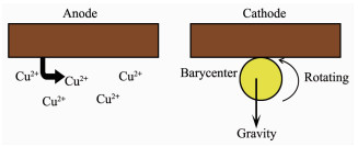
Cu is electrodeposited on the surface of PS/Au from the following bath in the same self-designed setup: Cu2P2O7·4H2O 70 g·L-1, K4P2O7 320 g·L-1, C4O6H4KNa 40 g·L-1, Na2HPO4 40 g·L-1, K3C6H5O7·H2O 18 gL-1, C6H5O7(NH4)3 18 g·L-1, SeO2 8 mg·g-1, C7H6N2S 2 mg·g-1. The anode of self-designed setup is replaced to copper, which be oxidized to copper ion supplying to solution near the cathode. Then the concentration of copper ion keeps the dynamic balance in the electrolyte solution. The principle of elctrodepositing and miscrosphere moving on the cathode is showing in Fig. 1. After considering the solution viscosity and the heated miscrospheres are swelled to Au film cracked, the solution temperature should not be higher. Accordingly, the experimental temperature is regulated to 45 ℃ after a lot of contrast experiment. For the hollow polystyrene microsphere covered the complete and thick Au layer and the greasy solution, the rotational speed is increased to 200 r·min-1. Then copper ions are mixed evenly in solution. The elctrodeposited microspheres are moving freely on the cathode. Due to NH3·H2O corroding the Cu layer, anode and cathode, pH value of the electrolyte solution is adjusted to 8(±0.5) with the addition of 30% KOH, not NH3·H2O. PH is more relatively stable to whole experiment process. Cu could be not electrodeposited on the surface of the PS/Au by the low current density. By the larger current density, Cu and oxide particles deposited on the surface of PS/Au and the cathode results in coarse grains. After a lot of experimental results are contrasted, the current density is controlled to 20 mA·cm-2. The experimental process of electrodeposited Cu lasts one hour.
Figure 1.
Principle of elctrodepositing and miscrosphere moving
1.4 Characterizations of Au electrodeposits and Cu electrodeposits
The integrity morphology of PS/Au is recorded by the KH-3000VD microscope. The surface and section morphologies and thickness of the electrodepositing Au and Au-Cu are analyzed by the TM-1000 SEM. The composition of the Au and Cu layers is analyzed by the EDS, attached the TM-1000 SEM.
2 Results and discussion
The integrity and spherical degree of PS/Au is important to copper plating. The good spherical degree of PS/Au microsphere can ensure microsphere moving freely and centrifugally on cathode. As is seen from Fig. 2, the microsphere has a diameter of about 500 μm. There is a center circle of the microsphere because of 3D microscope light projection, that demonstrates the microsphere keeps spherical symm-etric after magnetron sputtering and elecrodepositing. Fig. 3 shows the SEM image of the morphologies of Au film and section. The particles of the Au film are homogeneous and fine (Fig. 3a). The thickness of the Au film is quantified to approximately 5.6 μm (Fig. 3b). Throughout the course of the experiment, the cathode of Cu is corroded by NH3H2O adjusting pH to 8 leads to the bath becoming to blue. Consequently, it is tested whether the presence of impurity Cu in Au film by the EDS. The result of the analysis is shown in Fig. 3c. The result demonstrates there are not Cu and other impurities in Au film. NH3·H2O makes the deposition potential of Cu moving negative, thus Au and Cu are hardly codeposited by the low current density. Besides, SO32- in the bath complexing with Cu2+ produces a shielding effect. Cu has not been electrodeposited on the microsphere.
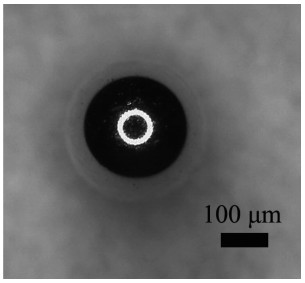 Figure 2.
3D-Video microscope image of PS-Au miscrosphere
Figure 2.
3D-Video microscope image of PS-Au miscrosphere
 Figure 3.
(a)~(b) SEM images of surface morphology and thickness of Au deposit; (c) EDS spectra of PS/Au composite microsphere
Figure 3.
(a)~(b) SEM images of surface morphology and thickness of Au deposit; (c) EDS spectra of PS/Au composite microsphere
The current density is a direct factor to the roughness and compactness of the electrodeposited Cu on PS/Au miscrosperes. The other influence factor are rotational speed, temperature, pH value, etc. Under the situation of other conditions being equal, the roughness of the electrodeposited Cu varies with different current densities (Table 1). The SEM images are shown in Fig. 4. Fig. 4a shows the morphology of the surface of the Cu film, which is rough and concavo-convex containing big white particles by the current density of 10 mA·cm-2 for 1hour. A small amount of Cu2+ gets electrons to form nuclei and grow because of the lower overpotential. With the current density increasing, the concavo-convex morphology of the Cu film has been significantly improved (as shown in Fig. 4b). With an increasing in cathodic polarization effect, the nucleate speed of Cu crystal increases obviously. Accordingly the Cu film becomes compact and smooth. Fig. 4c shows compact particle and smooth features of Cu deposits, which is very different from the rough surface of the Cu film by the current density of 20 mA·cm-2. When the current density continue to increase, the Cu film begins to become rough (Fig. 4d). Other conditions remain unchanged, The current density increases to 30 mA·cm-2, Cu anode is dissolved fast, a large number of Cu2+ exist in the bath. Small amounts of hydrogen are liberated on the surface of the cathode and the microspheres. The Cu film is coarse and exist pore. Besides, the PS/Au/Cu microsperes are preserved in alcohol for Cu oxidized easily. Fig. 4f presents the XRD patterns of the elecdeposited Cu film with six peaks, which are obtained at the center area from 40° to 120° of the surface of the PS/Au/Cu microspere with a scan rate of 1 min-1. The diffraction peaks are located at 2θ values of 38.1°, 44.2°, 64.6°, 77.7°, 81.7°, 98.0°, 111.7° and 114.6°, which perfectly match the (111), (200), (220), (311), (222), (400), (331) and (420) planes in the Cu face centered cubic crystal structure(PDF#03-064-8601), respectively. The absence of the diffraction peaks of Au and copper oxide indicates the high purity of the Cu film. In addition, the PS-Au microsphere covered the smooth and compact Cu film suggests that the PS/Au/Cu microsphere is prepared successfully.
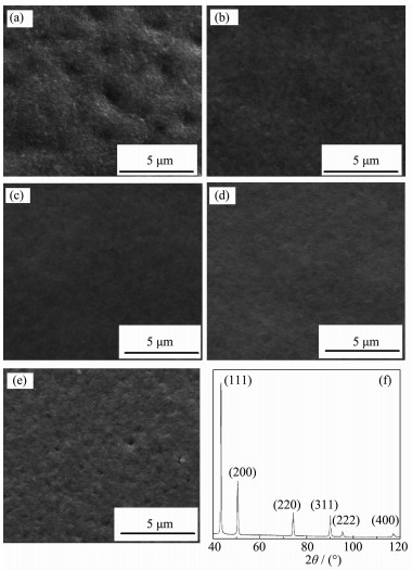 Figure 4.
SEM images of the surface of microspheres bydifferent current densities, (a) 10 mA·cm-2, (b) 15 mA·cm-2, (c)20 mA·cm-2, (d)25 mA·cm-2, (e) 30 mA·cm-2; (f) XRD pattern of the surface of the PS/Au/Cu microsphere
Figure 4.
SEM images of the surface of microspheres bydifferent current densities, (a) 10 mA·cm-2, (b) 15 mA·cm-2, (c)20 mA·cm-2, (d)25 mA·cm-2, (e) 30 mA·cm-2; (f) XRD pattern of the surface of the PS/Au/Cu microsphere
The morphologies of PS/Au/Cu and section are shown in Fig. 5. As shown in Fig. 5a, the Au-Cu film is integrated to cover the whole microsphere. Spherical symmetry of the microsphere keeps a good. The surface morphology is amplified in Fig. 5b. The surface is smooth to prove that grain is fine. The Fig. 5c shows the section of the double Au-Cu films. Cu grains grow along the surface of the Au film with lager nucleation driving force, because the grains of Au and Cu have the same face-centered cubic structure. This way of growth is called to grow along crystal, and the principle diagram is as shown in Fig. 5d. The Cu particles, arranging compactly, crystallize uniform. And the double films are in combination with well. The thickness of Cu is estimated to be about 8.62 μm, the Au is 4.04 μm. As the non soluble anode of Au, the depositing speed reduces because of Au3+ not supplemented in the solution, the thickness of Au has a differences. The composition analysis of the surface of the PS/Au/Cu is obtained by the EDS. Even if the Au and Cu have the same crystal structure, they do not mutually diffuse. In addition, there are no peaks of other impurities except Cu in Fig. 5e. The double Au-Cu films are covered the hollow polystyrene microsphere. The result meets the requirements of the experiment.
 Figure 5.
(a)~(c) SEM images of PS/Au/Cu composite microsphere, surface morphology and thickness of Au-Cu deposit; (d) Principle diagram of elerodeposited Cu; (e) EDS spectra of PS/Au/ Cu composite microsphere
Figure 5.
(a)~(c) SEM images of PS/Au/Cu composite microsphere, surface morphology and thickness of Au-Cu deposit; (d) Principle diagram of elerodeposited Cu; (e) EDS spectra of PS/Au/ Cu composite microsphere
-
-
[1]
李彬, 牛高, 易勇, 等.光谱学与光谱分析, 2016, 36(9):2812-2817 http://mall.cnki.net/magazine/Article/GUAN201609021.htmLI Bin, NIU Gao, YI Yong, et al. Spectrosc. Spect. Anal., 2016, 36(9):2812-2817 http://mall.cnki.net/magazine/Article/GUAN201609021.htm
-
[2]
武萱蓉, 杨巧珍, 赵勇祥.无机材料学报, 2016, 31(5):473-478 http://mall.cnki.net/magazine/Article/WGCL201605005.htmWU Xuan-Rong, YANG Qiao-Zhen, ZHAO Yong-Xiang. J. Inorg. Mater., 2016, 31(5):473-478 http://mall.cnki.net/magazine/Article/WGCL201605005.htm
-
[3]
毛倩瑾, 于彩霞, 王群.北京工业大学学报, 2003, 29(1):108-111 http://www.cqvip.com/QK/95054X/200301/7613371.htmlMAO Qian-Jin, YU Cai-Xia, WANG Qun. Journal of Beijing University of Technology, 2003, 29(1):108-111 http://www.cqvip.com/QK/95054X/200301/7613371.html
-
[4]
漆小波, 唐永建, 李波, 等.强激光与离子束, 2006, 18(1):55-60 http://www.cnki.com.cn/Article/CJFDTotal-QJGY200611017.htmQI Xiao-Bo, TANG Yong-Jian, LI Bo, et al. High Power Laser and Particle Beams, 2006, 18(1):55-60 http://www.cnki.com.cn/Article/CJFDTotal-QJGY200611017.htm
-
[5]
Nikroo A, Baugh W, Steinman D A. Fusion Sci. Technol., 45(2004):202-205
-
[6]
Rogach A, Susha A, Caruso F. Adv. Mater., 2000, 12:333-337 doi: 10.1002/(SICI)1521-4095(200003)12:5<333::AID-ADMA333>3.0.CO;2-X
-
[7]
Kato N, Caruso F. J. Phys. Chem. B, 2004, 109(42):19604-19612 doi: 10.2478/s11532-011-0024-8
-
[8]
Ou J L, Chang C P, Sung Y, et al. Colloids Surf. A, 2007, 304(123):36-41 http://www.sciencedirect.com/science/article/pii/S002627141100271X
-
[9]
刘惠玉, 陈东, 唐芳琼, 等.物理化学学报, 2006, 22(4):644-648 http://www.whxb.pku.edu.cn/CN/abstract/abstract23777.shtmlLIU Hui-Yu, CHEN Dong, TANG Fang-Qiong, et al. Acta Phys.-Chim. Sin., 2006, 22(4):644-648 http://www.whxb.pku.edu.cn/CN/abstract/abstract23777.shtml
-
[10]
王宇, 张骁勇, 毛丽, 等.材料科学与工程学报, 2004, 22(5):753-756 http://www.cqvip.com/qk/95998A/200405/WANG Yu, ZHANG Xiao-Yong, MAO Li, et al. J. Mater. Sci. Eng., 2004, 22(5):753-756 http://www.cqvip.com/qk/95998A/200405/
-
[11]
张建华, 卢忠远, 宋丽贤, 等.化工新型材料, 2007, 34(6):30-31 http://mall.cnki.net/magazine/Article/HGXC200706009.htmZHANG Jian-Hua, LU Zhong-Yuan, SONG Li-Xian, et al. New Chemical Materials, 2007, 34(6):30-31 http://mall.cnki.net/magazine/Article/HGXC200706009.htm
-
[12]
张冰杰, 杨文彬, 周元林, 等.强激光与粒子束, 2007, 19(4):744-748 http://www.cnki.com.cn/Article/CJFDTotal-QJGY200705011.htmZHANG Bin-Gjie, YANG Wen-Bin, ZHOU Yuan-Lin, et al. High Power Laser and Particle Beams, 2007, 19(4):744-748 http://www.cnki.com.cn/Article/CJFDTotal-QJGY200705011.htm
-
[13]
Jin R, Zhang Y W, Zhang L, et al. Appl. Surf. Sci., 264(2013):464-469 http://www.whxb.pku.edu.cn/EN/abstract/abstract29028.shtml
-
[14]
孙敬远, 张云望, 杜凯, 等.强激光与粒子束, 2010, 22(12):2889-2892 http://www.cqvip.com/QK/93571X/201012/2000010037.htmlSUN Jing-Yuan, ZHANG Yun-Wang, DU Kai, et al. High Power Laser and Particle Beams, 2010, 22(12):2889-2892 http://www.cqvip.com/QK/93571X/201012/2000010037.html
-
[15]
Peter A, Cerjan C, Hamza A, et al. Phys. Plasmas, 2007, 14:056312 doi: 10.1063/1.2716406
-
[16]
Jackson J B, Halas N J. J. Phys. Chem. B, 2001, 104(14):2743-2746 http://www.nature.com/nphoton/journal/v1/n11/full/nphoton.2007.223.html
-
[17]
Yong K T, Sahoo Y, Swihart M T, et al. Colloids Surf. A, 2006, 290(1/2/3):89-105 http://www.jccsoc.com/Magazine/Show.aspx?ID=48289
-
[18]
王瑛, 弭侃, 熊胜林.无机化学学报, 2017, 33(2):243-248 doi: 10.11862/CJIC.2017.048WANG Ying, MI Kan, XIONG Sheng-Lin. Chinese J. Inorg. Chem., 2017, 33(2):243-248 doi: 10.11862/CJIC.2017.048
-
[1]
-

Figure 3 (a)~(b) SEM images of surface morphology and thickness of Au deposit; (c) EDS spectra of PS/Au composite microsphere

Figure 4 SEM images of the surface of microspheres bydifferent current densities, (a) 10 mA·cm-2, (b) 15 mA·cm-2, (c)20 mA·cm-2, (d)25 mA·cm-2, (e) 30 mA·cm-2; (f) XRD pattern of the surface of the PS/Au/Cu microsphere
-


 下载:
下载:


 扫一扫看文章
计量
- PDF下载量: 5
- 文章访问数: 748
- HTML全文浏览量: 161
 下载:
下载:
