Figure 1.
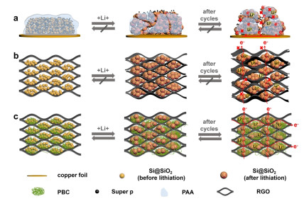
Electrode design and fabrication. Electrode structure changes of (a) SSSP, (b) SSG and (c) SSPBG in charge/discharge cycles.
An Advanced Design Concept of Mansion-like Freestanding Silicon Anodes with Improved Lithium Storage Performances
Deqing Zhang , Junfeng Ren , Caixia Li , Bin Luo , Lei Wang , Yanyan Li

In recent years, the market demand for lithium-ion battery anode materials has been increasing. In terms of the type of anode material, the anode material market will still be dominated by na-tural graphite and artificial graphite. However, the slow intercalation kinetics and low theoretical specific capacity (372 mAh g-1) of industrial graphite limit the rate capability of LIB.[1-6] With the gradual improvement of the demand for high-capacity and high-power anode materials in the whole market and the gradual maturity of the preparation process of the new generation of anode materials, the market focus will gradually shift to the new generation of anode materials.[7-22] As alternatives, Si has received extensive attention owing to its appropriate delithiation potential (0.4 V vs Li/Li+) and high theoretical capacity of 4200 mAh g-1 (Li22Si5).[4, 23, 24]2, 3 However, huge volume change (> 300%) during charge/discharge cycling and inherently low conductivity, which restricted the improvement of cycling stability and kinetics, have been recognized as two stumbling blocks standing in the way for the commercialization of Si anode.[24-27]
In order to overcome the volume expansion and electrical connection problems of silicon anode, there are several effective strategies, such as design and application of conductive binder, [28, 29] construction of efficient directional conductive network, [30] and structural design of silicon-carbon composites, [31] in which the hybridization of different dimensions (0D/0D, 0D/1D, 0D/2D) plays important roles in prolonging the lifetime of Si anode. For 0D/0D hybrid structure (e.g. "yolk-shell" hybrid structure), [32-34] the introduced carbon shell not only accommodates volume changes of Si, but also increases the conductivity, so as to enhance the storage capacity of LIBs. Additionally, 1D carbon (e.g. carbon nanotubes and nanofibers) could provide flexible concatenation for Si containing electrode materials, which plays crucial roles in alleviating the volume expansion.[35, 36] 2D materials are commonly referred to ultra-fine layered materials such as graphene and MXene which are also attractive substrates to develop stable sandwich structures for Si/C hybrid material.[37, 38] Although the above mentioned Si/C composites have greatly improved the electrochemical performance of Si anode, rapid capacity decay is inevitable during cycling, mainly due to insufficient connection and low electric connectivity of Si NPs to hosts.
Herein, we developed a 3D structured Si@SiO2/PBC/RGO (SSPBG) with multi-functional protection for Si NPs, as described in Figure 1. Traditional Si-binder-conductive collector systems face severe pulverization as well as electrical disconnection problems (Figure 1a). For RGO based binder free anodes, although position for volume change has been pre-reserved, the lack of conductive medium inside the electrode results in unsatisfactory structural stability (Figure 1b). While, this SSPBG electrode can be vividly described to a mansion-like building with separated rooms established by spring-like PBC and layer-structured RGO as accommodations for volume expansion of Si (Figure 1c). Therefore, sufficient rooms are created to pre-reserve space for volume expansion during charge/discharge process. Besides, RGO exhibits outstanding roles for the enhancement of electron conductivity due to delocalized π bonds.[39] PBC wires inserted into the RGO building blocks can stabilize the separated structure and avoid stacking of RGO layers, resulting in high stability of the whole electrode during cycling. In addition, compared with Si, SiOx has a smaller volume variation, which can inhibit adverse reactions and improve electrochemical cycle stability. The oxygen in SiO2 can react with Li+ to form Li2O and lithium silicate, which is beneficial to buffer volume expansion and maintains structural stability of the active material during the cycle.Meanwhile, the SEI layer formed on the surface of SiOx anode is more stable and intact than that formed on the surface of pure Si anode. Therefore, although SiOx has lower specific capacity than pure Si, its cyclic stability is significantly improved. As a result, Si NPs achieve controllable and reversible morphological changes in the cages formed by SiO2, RGO and PBC. As a proof-of-concept, these elaborately fabricated binder-free Si/C hybrid anodes can effectively withstand volume changes of Si NPs during charge and discharge, promote (de)alloying reactions with Li, and stabilize the electrode-electrolyte interfaces, thus reaching excellent electrochemical performance of 901 mAh g-1 at 2 A g-1 for 500 cycles.
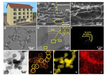
Structure and Compositions. The fabrication of SSPBG mainly depends on two facile steps: filtration and calcination, with high possibility for commercialization. This designed free-standing film can be depicted as mansions, with PBC as pillar and RGO as skeleton, working together to improve the stability of Si anodes (Figure 2a). The microstructure of SSPBG obtained after pyrolysis was featured by the scanning electron microscopy (SEM) and transmission electron microscopy (TEM). As presented in Figure 2b-c, interconnected 3D structure acts as networks for fast electron transfer and hosts for Si volume expansion. Therein, SiO2 has the characteristics of small volume expansion/contraction, so the encapsulation of conformal SiO2 can effectively inhibit the vo-lume change of Si NPs. PBC fibers wrap around each core-shell structure of Si@SiO2, acting as the buffer and conductive agents. In addition, layer-structured RGO walls could prevent Si NPs from inactivation and control suitable contact with electrolyte, thus forming a stable solid electrolyte interface film (SEI). In order to verify the mechanical strength of the prepared SSPBG electrode, we conducted flexibility and tensile strength tests (Figure S1). Figure S1a shows that the SSPBG electrode can be bent without breaking. Figure S1b shows the SSPBG electrode can withstand a weight of 10 g. It indicates that SSPBG electrode has excellent flexibility and mechanical strength. The thickness of SSPBG (~100 um) with self-supporting structure is shown in Figure 2b. It is noteworthy that the thicknesses of hybrid layers are controllable as required by adjusting the dosages (Figure S2). In sharp contrast, stacking and gathering of SSG and SSPB could be observed from Figure S3. For SSG, the accumulation of Si between layers of RGO leads to poor electrical conductivity and limits the full utilization of Si capacity. In the case of SSPB, there are no macropores which can accommodate large volume changes of Si due to the absence of RGO "skeleton". TEM was measured to further prove the interconnected structure of SSPBG (Figure 2d). High conductivity, interactive networks and short confusion path in SSPBG electrode contribute synergistically to fast ion and electron transfer during electrochemical reaction. As shown in the HR-TEM images of SSPBG (Figure 2e), core-shell structured Si@SiO2 NPs with size of ~50 nm are observed clearly with crystallized Si core and amorphous SiO2 shell. The lattice distance of the core was 0.31 nm corresponding to the (111) planes of crystalline Si.[40, 41] Furthermore, the SAED result of SSPBG indicates three distinct diffraction rings assigned to (111), (220) and (311) planes of polycrystalline Si (Figure 2f). Elemental mappings of SSPBG (Figure 2g) were adopted to manifest the distribution of O (orange), Si (yellow) and C (red) elements, which obviously indicates the uniform distribution of elements and presence of SiO2 shell on the Si NPs surface.[42]
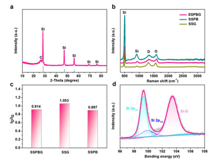
Chemical compositions of SSPBG and control electrode were featured by X-ray diffraction (XRD), Raman and X-ray photoelectron spectroscopy (XPS). XRD patterns of SSPBG in Figure 3a illustrate that all characteristic diffraction peaks match primely with (111), (220), (311), (400) and (331) planes of Si (JCPDS card No. 27-1402).[43] A broad peak at 26° could be attributed to the (002) planes of graphene.[37] Moreover, the Raman spectra of SSPBG, SSPB and SSG in Figure 3b illustrate that the sharp peak appearing at 508 cm-1 is caused by Si while the higher peek of SSPB electrode may be due to the fact that more Si NPs are exposed and detected without RGO wrapping. Two broad peaks at 1378 and 1594 cm-1 correspond to the disordered D band origin by the graphitic sp3-hybridization and G band from sp2 hybridized carbon, respectively.[44] Besides, the ID/IG radio of SSPBG is 0.914, showing partial defects and disordered structures. This value is between SSPB (0.897) and SSG (1.053), which may be related to the collective contribution of both PBC and RGO in SSPBG (Figure 3c).[37] To evaluate the chemical states of SSPBG composites, XPS tests were also conducted. High-resolution spectrum of Si 2p is exhibited in Figure 3d, which could be assigned to three peaks. The peaks located at 99.3 and 99.8 eV belong to Si 2p3/2 and 2p1/2 respectively, and another one at 103.4 eV is ascribed to Si-O bond from SiO2 shell.[45] As shown in the XPS results of Figure S4a, a weak peak for Si-O bond at around 103 eV is detected in raw Si, indicating the inevitable oxidization of Si NPs by the air. While, for SSPB, SSG and SSPBG, high intensities of Si-O bonds are observed owing to the further oxidization of Si by O-containing functional groups in BC and GO during pyrolysis process (Figure S4b-c, Figure 3d). Correspondingly, the SiO2 coating layer could not be observed in TEM images of raw Si (Figure S5), while SiO2 layers with thickness of 5 nm are clearly shown in Figure 2e for SSPBG, therefore further verifying the conclusion of XPS.
Interconnected pores and channels make great contribution in improving the electrolyte and ion transfer, so Brunauer-Emmett-Teller (BET) was employed to reveal the surface area and structure properties of the electrode. As shown in Figure S6, SSPBG, SSG and SSPB show different types of N2 adsorption and desorption isotherms due to the different addition amounts of BC. The more BC was added, the greater adsorption quantity in the low-pressure region, indicating that BC can increase the microporous structure of entire electrode, which is mainly attributed to the fact that BC can separate GO layers and avoid their re-stacking, thus significantly increasing the specific surface area of the electrode. In the low-pressure region, the adsorption quantity follows the trend of SSPB > SSPBG > SSG, consistent with the calculated specific surface area of SSPBG (136 m2 g−1), SSG (22 m2 g−1) and SSPB (270 m2 g−1).[46] Therefore, modest surface area and suitable pore-size provide Si containing anode with sufficient interfaces which could promote electrolyte infiltration as well as indicating unexpected SEI films.[47-49] Additionally, the Si contents in SSPBG, SSG and SSSP were expressed by thermo-gravimetric analysis (TGA) at a heating rate of 10 ℃ min-1 under air atmosphere (Figure S7). The increased weight of Si corresponds to the oxidation of Si to SiO2. For SSPBG, SSG, and SSSP, the weight loss is caused by the decomposition of C in air. Thus, the Si content of SSPBG, SSG and SSSP can be calculated from the following equation.
|
|
(1) |
Here, WSi, WC and WSi/C are the residual weight percentages of Si, C and SSPBG, SSG or SSSP, while XSi is the required content of Si. Given that the C is completely decomposed and the Wc is close to zero, the XSi value of SSPBG, SSG and SSSP could be calculated to be 67%, 68%, and 66%, respectively[50]. (Calculation results are listed in Table S1)
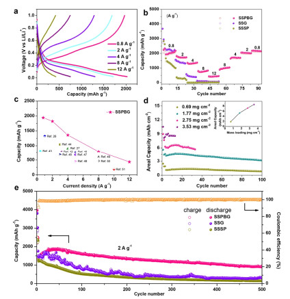
Electrochemical Performances. For the sake of investigating electrochemical features of SSPBG, Si containing composites were employed as a working electrode in the coin-type half-cell with lithium metal foil as the anode. Figure S8 exhibits the cyclic voltammetry (CV) curves of SSPBG between 0 and 1 V (vs Li/Li+) at a scan rate of 0.1 mv s-1 for initial four cycles. The broad cathodic peaks at around 1.1 V can be observed for SSPBG electrode in the first reduction process, but it becomes invisible afterwards, which can be assigned to the formation of an SEI film. In the subsequent cycles, a cathodic peak at ~0.14 V appears, related to the lithiation of Si to form LixSi (0≤x≤4.4). In the anodic scans, two oxidation peaks at ~0.35 and 0.57 V are observed, attributed to the delithiation of LixSi to form Si.[38] The rate capabilities of SSPBG, SSSP and SSG electrodes can be illustrated in Figure 4a-b with current densities from 0.8 to 12 A g-1. To note, the reversible capacities of SSPBG are detected to be 1940.6, 1820.5, 1357.8, 799.4 and 435.7 mAh g-1 at current density of 0.8, 2, 4, 8 and 12 A g-1 respectively, which is markedly higher than that of SSSP and SSG electrode, exceeding most of the reported silicon anodes (Figure 4c).[37, 38, 50-59]. As shown in Figure S9, the resistivity of SSPBG and SSG measured by a multimeter is 88 and 170.3 Ω, respectively, indicating that the addition of BC greatly increases the conductivity of the electrode. In order to further verify the important role of three-dimensional conductive network on electrode performance, we conducted electrochemical impedance spectroscopy (EIS) on electrodes (SSPBG, SSG and SSSP) before and after cycling, as shown in Figure S10a-b. Figure S10c is the equivalent circuit diagram established based on the fitting curve, with the results listed in Table S2. In the high frequency region, the intercept on the Z' axis can be attributed to the resistance between the electrolyte and separator (Rs), while the semicirons in the high-frequency and mid-frequency regions represent the resistance of the SEI layer (Rf) and charge transfer resistance (Rst), respectively. Obviously, the Rst value of fresh SSPBG electrode (381 Ohm) is lower than that of SSG (459 Ohm) and SSSP (1051 Ohm) in the fresh electrode, indicating high conductivity of SSPBG electrode. After 100 cycles, its Rst value becomes smaller (74.4 Ohm), so the three-dimensional conductive network inside SSPBG could improve the charge transfer ability. In addition, lithium ion diffusion resistance (Warburg impedance) of SSPBG electrode is significantly lower than that of SSG and SSSP in the low-frequency region.[50] Therefore, the established 3D conductive network accelerates the electron and ion transfer significantly, leading to expected electrochemical kinetics. It is generally considered that high areal mass loads are required in practical applications. As evaluated in Figure 4d, the areal capacity of SSPBG is in direct proportion to the mass loading of the active materials, with a reversible capacity of 8.57 mAh cm-2 (mass loading 3.53 mg cm-2 at 1 mA cm-2) which is much higher than the capacity (4 mAh cm-2) of commercial LIBs with graphite anode.[60] The excellent performance of SSPBG with high mass loading further demonstrates the best electron and ion transfer ability of SSPBG from one side to another. Figure 4e presents long cycling performance of SSPBG electrodes at 2 A g-1 for 500 cycles. The SSPBG electrode exhibits the highest reversible capacity of 901 mAh g-1 and stable Coulombic efficiency of 99.7% (The initial coulomb efficiency of SSPBG electrode (55%) is lower than that of SSG electrode (75%), which is mainly due to the increased specific surface area and excessive contact between silicon and electrolyte, thus consuming a large number of lithium ions.[61] Although the initial coulomb efficiency is low, the resulting stable SEI film contributes to the long cycle stability of the electrode). A comparison of this result with the cycle performance of other self-supported electrodes is given in Table S3. The increase in capacity of SSPBG electrode in the initial fifty cycles may be due to the activation process of electrode. The better performance could be ascribed to the interconnected conductive network, which not only acts as charge transfer channel, but also averts the structural collapse of the electrode. A fast capacity decay of only 308.4 mAh g-1 of SSG electrode can be found after 500 cycles, revealing the indispensable role of PBC in realizing long-term cycling stability. As for comparison, SSSP electrode has more serious capacity attenuation, mainly because of the structure pulverization and discontinuous connection of the electrode during cycling (Figure 1a). To further reveal the electrochemical dynamics of lithium storage, CV tests were performed on SSPBG electrodes at scanning rates of 0.1, 0.3, 0.5, 0.7 and 0.9 mV s-1. As shown in Figure S11a, CV curves have similar shapes and peak widths at different scanning rates. The mechanism of charge storage can be expressed in terms of the relationship between the measured current (i) and the scanning rate (v) in the following equation:
|
|
(2) |
Where, i is the measured current (A), v the scanning rate (V s-1), and a, b the fitting parameters. The fitting slope of log(v)-log(i) corresponds to the value of b. Generally, when b = 0.5, the diffusion controls the intercalation process, while b = 1 indicates the capacitor process without diffusion control. Figure S11b shows b = 0.6, so the SSPBG electrode has a battery-capacitor dual energy storage mechanism. According to the following formula, the contribution ratio of two different energy storage mechanisms at a specific scanning rate can be quantitatively calculated.
|
|
(3) |
Where, i (v), k1v, k2V1/2 and v are the current, capacitive current, diffusion control current and scanning rate under a given voltage correspondingly. By integral calculation, the contribution ratio of the two energy storage mechanisms in SSPBG electrodes at different scanning rates is shown in Figure S11c. With the increase of scanning rate, the pseudo capacitance effect of composites gradually increases. At the sweep speed of 0.9 mV S-1, the pseudo capacitance effect reaches 41%. These results indicate that storage process of SSPBG anode conforms to the battery-capacitor dual storage mechanism, which is conducive to the rapid charge and discharge and long period stability.
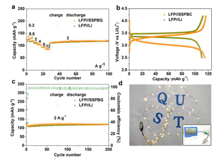
In order to further verify the feasibility of SSPBG in the commercialization of LIBs, we assembled the full battery with SSPBG as the anode and LiFePO4 as the cathode. Figure 5a exhibits that our LFP//SSPBG full cell possesses high-rate performance of 86.8 mAh g-1 even at 12 A g-1. Figure 5b shows the voltage distribution of our cell and LFP/Li half-cell, with the average voltage platforms of 3.23 and 3.43 V, respectively. At the current density of 2 A g-1, the prepared full cell by us exhibits a high reversible capacity of 120.9 mAh g-1 with coulombic efficiency of 98%, approaching to that of LFP//Li half-cell (Figure 5c). Figure 5d shows a light strip and electronic clock could be driven successfully by the LFP//SSPBG full cell, thereby demonstrating its practicality.
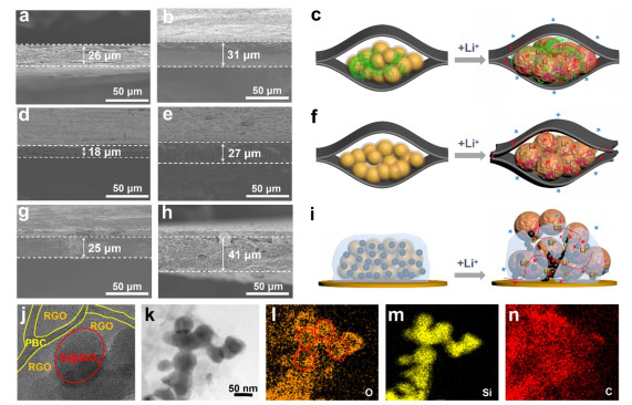
Structure Stability. To verity the stability and integrality of the structure, cross-section SEM images of SSPBG, SSG and SSSP electrode before and after cycles are displayed in Figure 6. As measured in Figure 6a-c, the SSPBG electrode shows only ~19% thickness change after 50 cycles, reflecting the ability of self-restraint. In sharp contrast, SSG (Figure 6d-f) goes through a huge volume change after 50 cycles, with the thickness increased by 50%. This could be attributed to the lack of recovery effect provided by the PBC upon volume expansion, which leads to huge change of the electrode thickness. As for SSSP electrode (Figure 6g-i), the thickness is increased by 64% after 50 cycles, indicating that conventional electrode with binders could not guarantee structural integrity. These results indicate that the 3D conductive network of SSPBG can accommodate the volume change of Si NPs effectively and ensure the structural integrity of the electrode. Correspondingly, TEM and corresponding EDS elemental mappings of SSPBG after 50 cycles are shown in Figure 6j-n. Although the volume expansion of Si NPs occurs, they are completely wrapped by SiO2 and RGO, and the PBC is interspersed between layers of RGO. From elemental mapping results of Si and O, the SiO2 shell is integrated after cycling, indicating its important role in maintaining structure integrity and increasing cycle stability of the electrode. Therefore, the designed mansion-like 3D structured SSPBG performance and excellent structure stability.
In conclusion, we have developed a new Si/C hybrid electrode with 3D mansion-like structure which displays excellent cycle stability, high areal capacity, and outstanding rate performances, mainly because the RGO acts as a "skeleton", while PBC performs as a "spring" for buffering volume changes for the electrode. PBC enhances the mechanical properties of the structure, increases the specific surface area of the electrode, and inhibits the volume expansion of Si effectively during the charge-discharge process. The designed 3D network structure achieves rapid electron and ion transfer without conductive additives and binders. This work provides an advanced concept for material/electrode design and opens a new way for the development of high-performance silicon electrodes. Furthermore, the potential of PBC to boost the performance of Si and other emerging energy storage materials has been realized.
Materials. Si@pSiO2 (Oxidation products of silicon in the air, < 50 nm), Super P (99%) and polyacrylic acid (25 wt% soln. in water) were purchased from Alfa Aesar Co. Ltd. Bacterial cellulose (BC) wet film was commercially available from Guilin Qihong Techno-logy Co. Ltd, graphene oxide from Shenzhen Hongda Chang Evolution Technology Co. Ltd, LiFePO4 from Shenzhen Kejing Zhida Co. Ltd, polyvinylidene fluoride (PVDF) from Canrd Chemical Technology Co. Ltd, and N-methyl-2-pyrrolidone (NMP, AR) from Sinopharm Chemical Reagent Co. Ltd. All chemicals were used directly without further purification.
Fabrication of Mansion-like 3D Structured SSPBG. In a typical synthesis, BC wet film was broken into pulp by a homogenizer at a rate of 10, 000 RPM for later use. Then, Si@pSiO2 and GO with a certain proportion were dispersed in 20 mL water using ultrasonication for 1 h. After that, the BC slurry prepared above was added to the mixture and stirred for 2 h (Si@pSiO2: GO: BC = 7:1:2) to get a uniform homogenate. Further, the mixed solution was va-cuumized to get the filter cake which was then freeze-dried for 12 h. Finally, the freeze-dried sample was calcined at 800 ℃ for 2 h in argon atmosphere at a heating rate of 5 ℃/min to obtain SSPBG. It should be noted that SSPBG anodes with different loading were prepared by controlling Si@pSiO2, BC and GO proportionally. The SSPB (Si@pSiO2: BC = 7:3) and SSG (Si@pSiO2: GO = 7:3) electrodes were prepared using the similar method as described for SSPBG. SSSP electrodes were made by casting slurries including active Si@pSiO2, conducting agent (Super P) and binder (polyacrylic acid) at a mass ratio of 7:2:1 on Cu foil.
Materials Characterization. The microstructure and morphologies of SSPBG and control samples were investigated by scanning electron microscopy (SEM, Hitachi S-4800) and transmission electron microscope (TEM, FEI Tecnaii-G2 F30, 300 KV). The composition and crystal morphology of the materials were analyzed by X-ray diffractometer (XRD, X'Pert-PRO MPD) within the scope of 10-90°. All synthesized samples were evaluated by a Raman spectroscope (Renishaw inVia confocal) with excitation wavelengths of 532 nm. The chemical states of the samples were tested by X-ray photoelectron spectroscopy (XPS, Axis Supra). Si contents in the materials were measured by a thermogravimetric analyzer (TGA, Netzsch TG-209F3) at a heating rate of 10 ℃/min from room temperature to 800 ℃ under the air atmosphere. The surface areas and porosities of SSPBG, SSPB and SSG were tested by Brunauer-Emmett-Teller (BET, Micrometrics, ASAP2460).
Measurements of Electrochemical Performances. The SSPBG, SSG and SSSP electrodes were employed firsthand as the working electrodes. Using porous polypropylene membrane (Celgard 2400) as separators and lithium foil as counter electrodes, a coin-type half-cell (CR 2032) was prepared in an Ar-filled glove box (oxygen and water < 0.01 parts per million). 1.2 M LiPF6 dissolved in dimethyl carbonate, ethylene carbonate and ethyl methyl carbonate (1:1:1 in volume) with 6 wt% fluoroethylene carbonate additive were used as the electrolyte and the dosage of electrolyte was 100 µL. In addition, the full cell was designed with a N/P ratio of ≈1.1. It should be noted that the SSPBG electrodes were pre-lithium before the full battery was assembled. The electrochemical prelithiation of SSPBG was conducted on a coin type half-cell with SSPBG as the cathode and Li metal foil as the anode. The pre-lithium process is carried out in a voltage range of 0.02-1 V with a current density of 0.2 A g-1 for 9 charge-discharge cycles (fully de-lithiated), with the last cycle ending with a discharge to 0.02 V. The cathode electrodes were prepared by mixing LiFePO4, super P, and PVDF in NMP solution at a mass ratio of 8:1:1, casting, and vacuum drying at 80 ℃ for 8 h. The full-cell has the same electrolyte and separator as the half-cell, and the electrochemical tests were performed under a voltage window of 2.5 to 4.2 V. The cycle-stability and rate-performance of the half-cell were tested in the voltage range of 0.02-1.0 V using the LAND test system (CT3002A). Cyclic voltammetry (CV) was implemented in the potential range of 0-1.0 V at a rate of 0.1 mV s−1 and electrochemical impedance spectra (EIS) were examined with an electrochemical workstation (biologic, VSP). Unless otherwise specified, the reported capacity was based on the total weight of active substance in the working electrode.
Takami, N.; Satoh, A.; Hara, M.; Ohsaki, T. Structural and kinetic characterization of lithium intercalation into carbon anodes for secondary lithium batteries. J. Electroanal. Chem. 1995, 142, 371. doi: 10.1149/1.2044017
Levi, M. D.; Aurbach, D. Diffusion coefficients of lithium ions during intercalation into graphite derived from the simultaneous measurements and modeling of electrochemical impedance and potentiostatic intermittent titration characteristics of thin graphite electrodes. J. Phys. Chem. B 1997, 101, 4641-4647.
Yu, P.; Popov, B. N.; Ritter, J. A.; White, R. E. Determination of the lithium ion diffusion coefficient in graphite. J. Electrochem. Soc. India 1999, 146, 8. doi: 10.1149/1.1391556
Zhang, C.; Kang, T. H.; Yu, J. S. Three-dimensional spongy nanographene-functionalized silicon anodes for lithium ion batteries with superior cycling stability. Nano Res. 2017, 11, 233-245.
Xia, L.; Wang, S.; Liu, G.; Ding, L.; Li, D.; Wang, H.; Qiao, S. Flexible SnO2/N-doped carbon nanofiber films as integrated electrodes for lithium-ion batteries with superior rate capacity and long cycle life. Small 2016, 12, 853-859. doi: 10.1002/smll.201503315
Jia, L.; Ji, Y.; Wang, Z.; Yang, K.; Chen, H.; Pan, F. Interface reconstruction study by functional scanning probe microscope in Li-ion battery research. Chin. J. Struct. Chem. 2020, 39, 200-205.
Van Noorden, R. A better battery. Nature 2014, 507, 26. doi: 10.1038/507026a
Goodenough, J. B.; Park, K. S. The Li-ion rechargeable battery: a perspective. J. Am. Chem. Soc. 2013, 135, 1167-1176. doi: 10.1021/ja3091438
Wang, L.; Zhuo, L.; Zhao, F. Carbon dioxide-expanded ethanol-assisted synthesis of carbon-based metal composites and their catalytic and electrochemical performance in lithium-ion batteries. Chin. J. Catal. 2016, 37, 218-226. doi: 10.1016/S1872-2067(15)61024-5
Wang, R.; Wang, S.; Jin, D.; Zhang, Y.; Cai, Y.; Ma, J.; Zhang, L. Engineering layer structure of MoS2-graphene composites with robust and fast lithium storage for high-performance Li-ion capacitors. Energy Storage Mater. 2017, 9, 195-205. doi: 10.1016/j.ensm.2017.07.013
Cui, G. Reasonable design of high-energy-density solid-state lithium-metal batteries. Matter 2020, 2, 805-815. doi: 10.1016/j.matt.2020.02.003
Guo, Y.; Chen, Y. N.; Cui, H.; Zhou, Z. Bifunctional electrocatalysts for rechargeable Zn-air batteries. Chin. J. Catal. 2019, 40, 1298-1310. doi: 10.1016/S1872-2067(19)63349-8
Schmuch, R.; Wagner, R.; Hörpel, G.; Placke, T.; Winter, M. Performance and cost of materials for lithium-based rechargeable automotive batteries. Nat. Energy 2018, 3, 267-278. doi: 10.1038/s41560-018-0107-2
Li, X.; Yang, S.; Feng, N.; He, P.; Zhou, H. Progress in research on Li-CO2 batteries: mechanism, catalyst and performance. Chin. J. Catal. 2016, 37, 1016-1024. doi: 10.1016/S1872-2067(15)61125-1
Liu, B.; Shioyama, H.; Jiang, H.; Zhang, X.; Xu, Q. Metal-organic framework (MOF) as a template for syntheses of nanoporous carbons as electrode materials for supercapacitor. Carbon 2010, 48, 456-463. doi: 10.1016/j.carbon.2009.09.061
Chao, D.; Zhou, W.; Ye, C.; Zhang, Q.; Chen, Y.; Gu, L.; Davey, K.; Qiao, S. Z. An electrolytic Zn-MnO2 battery for high-voltage and scalable energy storage. Angew. Chem. Int. Ed. 2019, 131, 7905-7910. doi: 10.1002/ange.201904174
Xu, G.; Li, J.; Wang, C.; Du, X.; Lu, D.; Xie, B.; Wang, X.; Lu, C.; Liu, H.; Dong, S. The formation/decomposition equilibrium of LiH and its contribution on anode failure in practical lithium metal batteries. Angew. Chem. Int. Ed. 2021, 133, 7849-7855. doi: 10.1002/ange.202013812
Wu, F.; Liu, M.; Li, Y.; Feng, X.; Zhang, K.; Bai, Y.; Wang, X.; Wu, C. High-mass-loading electrodes for advanced secondary batteries and supercapacitors. Electrochem. Energy R 2021, 4, 382-446. doi: 10.1007/s41918-020-00093-0
Liu, Y.; Li, W.; Xia, Y. Recent progress in polyanionic anode materials for Li(Na)-ion batteries. Electrochem. Energy R 2021, 4, 447-472. doi: 10.1007/s41918-021-00095-6
Boyjoo, Y.; Shi, H.; Tian, Q.; Liu, S.; Liang, J.; Wu, Z. S.; Jaroniec, M.; Liu, J. Engineering nanoreactors for metal-chalcogen batteries. Energ. Environ. Sci. 2021, 14, 540-575. doi: 10.1039/D0EE03316B
Zhong, X.; Papandrea, B.; Xu, Y.; Lin, Z.; Zhang, H.; Liu, Y.; Huang, Y.; Duan, X. Three-dimensional graphene membrane cathode for high energy density rechargeable lithium-air batteries in ambient conditions. Nano Res. 2017, 10, 472-482. doi: 10.1007/s12274-016-1306-4
Boyjoo, Y.; Shi, H.; Olsson, E.; Cai, Q.; Wu, Z. S.; Liu, J.; Lu, G. Q. Molecular-level design of pyrrhotite electrocatalyst decorated hierarchical porous carbon spheres as nanoreactors for lithium-sulfur batteries. Adv. Energy Mater. 2020, 10, 2000651. doi: 10.1002/aenm.202000651
Yoon, J. H.; Lee, G.; Li, P.; Baik, H.; Yi, G. R.; Park, J. H. Expandable crosslinked polymer coatings on silicon nanoparticle anode toward high-rate and long-cycle-life lithium-ion battery. Appl. Surf. Sci. 2022, 571, 151294. doi: 10.1016/j.apsusc.2021.151294
Xie, Q.; Qu, S.; Zhao, P. A facile fabrication of micro/nano-sized silicon/carbon composite with a honeycomb structure as high-stability anodes for lithium-ion batteries. J. Electroanal. Chem. 2021, 884, 115074. doi: 10.1016/j.jelechem.2021.115074
McSweeney, W.; Geaney, H.; O'Dwyer, C. Metal-assisted chemical etching of silicon and the behavior of nanoscale silicon materials as Li-ion battery anodes. Nano Res. 2015, 8, 1395-1442. doi: 10.1007/s12274-014-0659-9
Zhang, C.; Wang, F.; Han, J.; Bai, S.; Tan, J.; Liu, J.; Li, F. Challenges and recent progress on silicon-based anode materials for next-generation lithium-ion batteries. Small Struct. 2021, 2, 2100009. doi: 10.1002/sstr.202100009
Liu, H.; Wei, C.; Peng, H.; Ma, W.; Wang, Y.; Zhang, L.; Lu, C.; Ma, C.; Shi, J. Improved lithium storage performance by encapsulating silicon in free-standing 3D network structure carbon-based composite membranes as flexible anodes. Surf. Coat. Technol. 2021, 423, 127606. doi: 10.1016/j.surfcoat.2021.127606
Song, Z.; Chen, S.; Zhao, Y.; Xue, S.; Qian, G.; Fang, J.; Zhang, T.; Long, C.; Yang, L.; Pan, F. Constructing a resilient hierarchical conductive network to promote cycling stability of SiOx anode via binder design. Small 2021, 17, 2102256. doi: 10.1002/smll.202102256
Song, Z.; Zhang, T.; Wang, L.; Zhao, Y.; Li, Z.; Zhang, M.; Wang, K.; Xue, S.; Fang, J.; Ji, Y. Bio-inspired binder design for a robust conductive network in silicon-based anodes. Small Methods 2022, 2101591.
Yang, K.; Yang, L.; Wang, Z.; Guo, B.; Song, Z.; Fu, Y.; Ji, Y.; Liu, M.; Zhao, W.; Liu, X.; Yang, S.; Pan, F. Constructing a highly efficient aligned conductive network to facilitate depolarized high-areal-capacity electrodes in Li-ion batteries. Adv. Energy Mater. 2021, 11, 2100601. doi: 10.1002/aenm.202100601
Yang, Y.; Yang, J.; Pan, F.; Cui, Y. From intercalation to alloying chemistry: structural design of silicon anodes for the next generation of lithium-ion batteries. Chin. J. Struct. Chem. 2020, 39, 16-19.
Huang, X.; Sui, X.; Yang, H.; Ren, R.; Wu, Y.; Guo, X.; Chen, J. HF-free synthesis of Si/C yolk/shell anodes for lithium-ion batteries. J. Mater. Chem. A 2018, 6, 2593-2599. doi: 10.1039/C7TA08283E
Guo, S.; Hu, X.; Hou, Y.; Wen, Z. Tunable synthesis of yolk-shell porous silicon@carbon for optimizing Si/C-based anode of lithium-ion batteries. ACS Appl. Mater. Inter 2017, 9, 42084-42092. doi: 10.1021/acsami.7b13035
Fu, L.; Xu, A.; Song, Y.; Ju, J.; Sun, H.; Yan, Y.; Wu, S. Pinecone-like silicon@carbon microspheres covered by Al2O3 nano-petals for lithium-ion battery anode under high temperature. Electrochim. Acta 2021, 387, 138461. doi: 10.1016/j.electacta.2021.138461
Feng, X.; Yang, J.; Bie, Y.; Wang, J.; Nuli, Y.; Lu, W. Nano/micro-structured Si/CNT/C composite from nano-SiO2 for high power lithium ion batteries. Nanoscale 2014, 6, 12532-12539. doi: 10.1039/C4NR03948C
Kim, J. M.; Guccini, V.; Kim, D.; Oh, J.; Park, S.; Jeon, Y.; Hwang, T.; Salazar-Alvarez, G.; Piao, Y. A novel textile-like carbon wrapping for high-performance silicon anodes in lithium-ion batteries. J. Mater. Chem. A 2018, 6, 12475-12483. doi: 10.1039/C8TA01414K
Zhang, X.; Wang, D.; Zhang, S.; Li, X.; Zhi, L. A hierarchical layering design for stable, self-restrained and high volumetric binder-free lithium storage. Nanoscale 2019, 11, 21728-21732. doi: 10.1039/C9NR08215H
Xia, M.; Chen, B.; Gu, F.; Zu, L.; Xu, M.; Feng, Y.; Wang, Z.; Zhang, H.; Zhang, C.; Zhang, C. Ti3C2Tx MXene nanosheets as a robust and conductive tight on Si anodes significantly enhance electrochemical lithium storage performance. ACS Nano 2020, 14, 5111-5120. doi: 10.1021/acsnano.0c01976
Kucinskis, G.; Bajars, G.; Kleperis, J. Graphene in lithium ion battery cathode materials: a review. J. Power Sources 2013, 240, 66-79. doi: 10.1016/j.jpowsour.2013.03.160
Wang, B.; Li, W.; Wu, T.; Guo, J.; Wen, Z. Self-template construction of mesoporous silicon submicrocube anode for advanced lithium ion batteries. Energy Storage Mater. 2018, 15, 139-147. doi: 10.1016/j.ensm.2018.03.025
Kim, N.; Park, H.; Yoon, N.; Lee, J. K. Zeolite-templated mesoporous silicon particles for advanced lithium-ion battery anodes. ACS Nano 2018, 12, 3853-3864. doi: 10.1021/acsnano.8b01129
Ge, G.; Li, G.; Wang, X.; Chen, X.; Fu, L.; Liu, X.; Mao, E.; Liu, J.; Yang, X.; Qian, C.; Sun, Y. Manipulating oxidation of silicon with fresh surface enabling stable battery anode. Nano Lett. 2021, 21, 3127-3133. doi: 10.1021/acs.nanolett.1c00317
Zhang, X.; Guo, R.; Li, X.; Zhi, L. Scallop-inspired shell engineering of microparticles for stable and high volumetric capacity battery anodes. Small 2018, 14, 1800752. doi: 10.1002/smll.201800752
Li, P.; Hwang, J. Y.; Sun, Y. K. Nano/microstructured silicon-graphite composite anode for high-energy-density Li-ion battery. ACS Nano 2019, 13, 2624-2633.
Jakša, G.; Štefane, B.; Kovač, J. Influence of different solvents on the morphology of APTMS-modified silicon surfaces. Appl. Surf. Sci. 2014, 315, 516-522. doi: 10.1016/j.apsusc.2014.05.157
Li, G.; Zhang, B.; Yan, J.; Wang, Z. Micro- and mesoporous poly(Schiff-base)s constructed from different building blocks and their adsorption behaviors towards organic vapors and CO2 gas. J. Mater. Chem. A 2014, 2, 18881-18888. doi: 10.1039/C4TA04429K
Jin, Y.; Zhu, B.; Lu, Z.; Liu, N.; Zhu, J. Challenges and recent progress in the development of Si anodes for lithium-ion battery. Adv. Energy Mater. 2017, 7, 1700715. doi: 10.1002/aenm.201700715
Chan, C. K.; Peng, H.; Liu, G.; McIlwrath, K.; Zhang, X. F.; Huggins, R. A.; Cui, Y. High-performance lithium battery anodes using silicon nanowires. Nat. Nanotechnol. 2008, 3, 31-35. doi: 10.1038/nnano.2007.411
Gao, H.; Xiao, L.; Plümel, I.; Xu, G. L.; Ren, Y.; Zuo, X.; Liu, Y.; Schulz, C.; Wiggers, H.; Amine, K. Parasitic reactions in nanosized silicon anodes for lithium-ion batteries. Nano Lett. 2017, 17, 1512-1519. doi: 10.1021/acs.nanolett.6b04551
Zhu, R.; Wang, Z.; Hu, X.; Liu, X.; Wang, H. Silicon in hollow carbon nanospheres assembled microspheres cross-linked with N-doped carbon fibers toward a binder free, high performance, and flexible anode for lithium-ion batteries. Adv. Funct. Mater. 2021, 31, 2101487. doi: 10.1002/adfm.202101487
Wu, J.; Qin, X.; Zhang, H.; He, Y. B.; Li, B.; Ke, L.; Lv, W.; Du, H.; Yang, Q. H.; Kang, F. Multilayered silicon embedded porous carbon/graphene hybrid film as a high performance anode. Carbon 2015, 84, 434-443. doi: 10.1016/j.carbon.2014.12.036
Lin, H.; Weng, W.; Ren, J.; Qiu, L.; Zhang, Z.; Chen, P.; Chen, X.; Deng, J.; Wang, Y.; Peng, H. Twisted aligned carbon nanotube/silicon composite fiber anode for flexible wire-shaped lithium-ion battery. Adv. Mater. 2014, 26, 1217-1222. doi: 10.1002/adma.201304319
Bao, W.; Wang, J.; Chen, S.; Li, W.; Su, Y.; Wu, F.; Tan, G.; Lu, J. A three-dimensional hierarchical structure of cyclized-PAN/Si/Ni for mechanically stable silicon anodes. J. Mater. Chem. A 2017, 5, 24667-24676. doi: 10.1039/C7TA08744F
Xu, S.; Zhou, J. G.; Wang, J.; Pathiranage, S.; Oncel, N.; Ilango, P. R.; Zhang, X.; Mann, M.; Hou, X. D. In situ synthesis of graphene-coated silicon monoxide anodes from coal-derived humic acid for high-performance lithium-ion batteries. Adv. Funct. Mater. 2021.
Qu, E.; Chen, T.; Xiao, Q.; Lei, G.; Li, Z. Freestanding silicon/carbon nanofibers composite membrane as a flexible anode for Li-Ion battery. J. Power Sources 2018, 403, 103-108. doi: 10.1016/j.jpowsour.2018.09.086
Wang, M. S.; Song, W. L.; Wang, J.; Fan, L. Z. Highly uniform silicon nanoparticle/porous carbon nanofiber hybrids towards free-standing high-performance anodes for lithium-ion batteries. Carbon 2015, 82, 337-345. doi: 10.1016/j.carbon.2014.10.078
Zhou, Y.; Yang, Y.; Hou, G.; Yi, D.; Zhou, B.; Chen, S.; Lam, T. D.; Yuan, F.; Golberg, D.; Wang, X. Stress-relieving defects enable ultra-stable silicon anode for Li-ion storage. Nano Energy 2020, 70, 104568. doi: 10.1016/j.nanoen.2020.104568
Zhu, S.; Zhou, J.; Guan, Y.; Cai, W.; Zhao, Y.; Zhu, Y.; Zhu, L.; Zhu, Y.; Qian, Y. Hierarchical graphene-scaffolded silicon/graphite composites as high performance anodes for lithium-ion batteries. Small 2018, 14, 1802457. doi: 10.1002/smll.201802457
Zhang, J.; Chen, Y.; Chen, X.; Feng, T.; Yang, P.; An, M. Preparation of graphene-like carbon attached porous silicon anode by magnesiothermic and nickel-catalyzed reduction reactions. Ionics 2020, 26, 5941-5950. doi: 10.1007/s11581-020-03746-8
Zhang, X.; Wang, D.; Qiu, X.; Ma, Y.; Kong, D.; Mullen, K.; Li, X.; Zhi, L. Stable high-capacity and high-rate silicon-based lithium battery anodes upon two-dimensional covalent encapsulation. Nat. Commun. 2020, 11, 3826. doi: 10.1038/s41467-020-17686-4
Zhu, R.; Li, L.; Wang, Z.; Zhang, S.; Dang, J.; Liu, X.; Wang, H. Adjustable dimensionality of microaggregates of silicon in hollow carbon nanospheres: an efficient pathway for high-performance lithium-ion batteries. ACS Nano 2021.

Figure 1 Electrode design and fabrication. Electrode structure changes of (a) SSSP, (b) SSG and (c) SSPBG in charge/discharge cycles.

Figure 2 Morphological and structural characterization of SSPBG. (a) A sketch of a mansion. (b-c) Cross-sectional SEM images of SSPBG. The inset of the figure b shows the thickness of ~100 μm for the self-supported electrode. (d) TEM image, (e) HRTEM, (f) SAED, and (g) element mapping of SSPBG.

Figure 3 Characterization of SSPBG. (a) XRD pattern of SSPBG. (b) Raman spectra and (c) the corresponding ID/IG of SSPBG and control electrodes. (d) Si 2p spectrum of SSPBG.

Figure 4 Electrochemical characterization of SSPBG. (a) Voltage profiles of SSPBG at different current densities. (b) Rate performance of SSPBG, SSG and SSSP. (c) Comparison with representative silicon anodes in the literature as noted. (d) Areal capacity of SSPBG with various masses tested at 1 mA cm-2. (e) Cyclability of the SSPBG and control electrodes tested at 2 A g-1.

Figure 5 Electrochemical performance of LiFePO4//SSPBG. (a) Rate capability and (b) orresponding charge/discharge profiles of LFP//SSPBG full cell and LFP//Li half-cell at different current density range from 0.8 to 12 A g-1. (c) Capacity and coulombic efficiency versus cycle number plot of the LFP//SSPBG full cell and LFP//Li half-cell. (d) A light strip and electronic clock successfully ignited by the LFP//SSPBG full battery.

Figure 6 Thickness changes of SSPBG and control electrodes after 50 cycles at 2 A g-1. Cross-section SEM images of (a, b) SSPBG, (d, e) SSG and (g, h) SSSP electrode before (a, d, g) and after (b, e, h) 50 cycles. The section thickness variation diagram of (c) SSPBG, (f) SSG and (i) SSSP. (j-n) TEM and corresponding EDS elemental mappings of SSPBG after 50 cycles.

 扫一扫看文章

扫一扫关注我们
 DownLoad:
 下载:
下载:
 下载:
下载: