The First-principles Study on the Rectification of Molecular Junctions Based on the Alkyl-chain-modified [2, 5΄]Bipyrimidinyl(biphenyl isocyanide)gold(I)
Citation:
Quan-Dang GAO, E YANG. The First-principles Study on the Rectification of Molecular Junctions Based on the Alkyl-chain-modified [2, 5΄]Bipyrimidinyl(biphenyl isocyanide)gold(I)[J]. Chinese Journal of Structural Chemistry,
2020, 39(10): 1763-1769.
doi:
10.14102/j.cnki.0254–5861.2011–2690
The First-principles Study on the Rectification of Molecular Junctions Based on the Alkyl-chain-modified [2, 5΄]Bipyrimidinyl(biphenyl isocyanide)gold(I)
The First-principles Study on the Rectification of Molecular Junctions Based on the Alkyl-chain-modified [2, 5΄]Bipyrimidinyl(biphenyl isocyanide)gold(I)
College of Chemistry and Materials Science, Fujian Normal University, Fuzhou 350007, China
b.
State Key Laboratory of Structural Chemistry, Fujian Institute of Research on the Structure of Matter, Chinese Academy of Sciences, Fuzhou 350002, China
Received Date:
09 December 2019 Accepted Date:
10 February 2020 Available Online:
01 October 2020
Fund Project:
Abstract:
Using density functional theory (DFT) combined with nonequilibrium Green΄s function investigates the electron-transport properties of several molecular junctions based on the [2, 5΄]bipyrimidinyl(biphenyl isocyanide)gold(I) molecule (BPM-Au(I)CN-BP), which is modified by one to three alkyl groups forming BPM-Au(I)CN-BP(CH2)n. The asymmetric current-voltage characteristics have been obtained for the molecular junctions. Rectifying performance of Au/S-BPM-Au(I)CN-BP-S/Au molecular junction can be regulated by introducing alkyl chain. The M1 molecular junction exhibits the best rectifying effect. Its maximum rectifying ratio is 2109, which is about 150 times more than that of the molecular junction based on the original M. Moreover, all the systems modified by alkyl group have obvious negative differential resistance behavior (NDR). The current-voltage (I-V) curves of all the systems in this work are illustrated by transmission spectra.
With the electronic devices getting miniaturized, the size of device has been changed which is going from microscale into the nanoscale[1]. However, the change is unlikely to becontinuing, which means that Moore΄s law is approaching its physical limit[2]. At this critical moment, Feynman[3] proposed that manipulating molecules to build nanodevice will become an effective solution to the dilemma. Therefore, it is extremely urgent to research a series of functional molecular devices[4]. Additionally, researches based on laboratory are also limited by their experimental technology and the precision of instruments. On the contrary, theoretical calculation becomes innovative to traditional experimental methods. In conclusion, theoretical calculation is able to process qualitative analysis in valid on the molecular level. Along with the deepened study gradually, plenty of functional molecular devices have been discovered and announced to the public, such as molecular switch[5, 6], molecular rectifier[7, 8], negative differential resistance effect[9, 10] and so on[11, 12]. Introducing asymmetric factors[13] into molecular devices is able to acquire the rectifiers of differential electronic transporting. There are many factors that can influence molecular rectification, like the contact performance between molecule and electrode[14], the influence of substituent[15], the asymmetric effect of electrode[16], etc. The research will demonstrate that introducing asymmetric factors into molecular junctions by using the alkyl-chain[4, 17] to modify the molecular rectifier is one of the effective ways. Very recently, gold(I) isocyanide compounds with a new phenomenon related to the mechanoresponsive luminescence properties have been reported[18-20], so the [2, 5΄]bipyrimidinyl(biphenyl isocyanide)-gold(I) molecule (BPM-Au(I)CN-BP) modified by one to three alkyl groups has been studied. The transport properties of Au/S-BPM-Au(I)CN-BP(CH2)n-S/Au have been investigated by density functional theory (DFT) combined with non-equilibrium Green΄s function.
2.
COMPUTATIONAL DETAILS
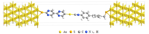
Fig. 1 illustrates the models of molecular junctions M to M3 with metal/molecule/metal structures. In each so-called two probe system, a thiolate-ended molecule based on BPM-Au(I)CN-BP is sandwiched between two gold electrodes. The thiol end group is employed widely in the field of molecular devices. Molecules containing thiol end groups can be self-assembled on the Au substrate because the hydrogen atom in the thiol group will be dissociated and strong Au-S covalent bonds will form when the thiol group interacts with Au surface. The two Au(111)-(3×3) surfaces (i.e., each layer consisting of nine gold atoms) with periodic boundary conditions have been used to model the left and right electrodes[21, 22]. The molecule in the central region of system M is an original dithiol-terminated BPM-Au(I)CN-BP. The molecules in the central region of systems M1 to M3 are HS-BPM-Au(I) CN-BPCH2-SH, HS-BPM-Au(I) CN-BP(CH2)2-SH, HS-BPM-Au(I)CN-BP(CH2)3-SH, respectively, which are the modified HS-BPM-Au(I)CN-BP-SH with one to three alkyl groups.
Figure 1
Figure 1.
Schematic view of the two-probe Au/S-BPM-Au(I)CN-BPCH2-S/Au molecular junction (M1); The central moleculeBPM-Au(I)CN-BPCH2 replaced by BPM-Au(I)CN-BP, S–BPM-Au(I)CN-BP(CH2)2 and BPM-Au(I)CN-BP(CH2)3 is Corresponding to M, M2 and M3 molecular junctions, respectively. These thiolate-ended molecules self-assemble on the Au(111)-(3×3)surface, and consist of the two-probe Au/molecule/Au systems with right and left semi-infinite electrodes and the scattering region
The whole computation is composed of two procedures. First, the geometry optimization and electronic structures of the isolated molecules in the central region in Fig. 1 have been performed using the Gaussian03 program[23] at the hybrid DFT/B3LYP[24, 25] level of theory with the 6-311G(d, p) and LANL2DZ basis sets. The next procedure is the transport computation after the above geometry optimization. The geometries of the isolated molecules are extracted from the optimized extended molecules and then translated into the central region between the two gold electrodes, as illustrated in Fig. 1. The two Au(111)-(3×3) surfaces with periodic boundary conditions are used to model the left and right electrodes. The Au/molecule/Au configuration is divided into three parts: left electrode, right electrode, and central scatting region. In the models, there are three gold layers in each left and right electrode unit cells. The scattering region is composed of the isolated molecule together with the respective three gold layers on the left and right sides. The distance between the Au(111) surface and the terminal S atom is 2.28 Å, which falls in the range from 1.90 to 2.39 Å used by most studies[26]. The electron-transport properties of the metal/molecule/metal systems have been investigated using ab initio software package, Atomistix ToolKit (ATK)[27, 28], which is based on DFT combined with the first-principles non-equilibrium Green΄s function (NEGF). In this work, a double-ξ polarization (DZP) basis set is used for all nonmetallic atoms of molecule except H, and a single-ξ with polarization (SZP) basis set is used for Au and H atoms. The exchange-correlation potential is described by the Perdew-Burke-Ernzerhof (PBE) version of the generalized gradient approximation (GGA)[29, 30]. The convergence criterion is set to 1×10⁻⁵ for grid integration to obtain accurate results. A k-point sampling of 3×3×100 is used for the metal-electrode models. On a real-space grid, a mesh cutoff energy of the charge density and potentials is set to150 Ha.
In these molecular junctions, the current-voltage (I-V) characteristics are obtained from the Landauer-Büttiker formula[23].
$I\left(V_b\right)=\frac{2 e^2}{h} \int_{u_L}^{u_R}\left[f\left(E-u_L\right)-f\left(E-u_R\right)\right] T\left(E, V_b\right) d E $
(1)
where 2e2/h = G0 is the quantum unit of conductance, e expresses the elementary charge and h shows the Planck΄ s constant. f is the Fermi function, μR and μL are respectively the electrochemical potentials of the right and left electrodes: μR(Vb) = Ef + eVb/2 and μL(Vb) = Ef – eVb/2, where Ef represents the Fermi energy of the electrode, and [μL(Vb), μR(Vb)] shows the current integral, known as the energy region of the bias window. T(E, Vb) is the transmission function for an incident electron with energy E at a bias voltage Vb.
3.
RESULTS AND DISCUSSION
3.1
Electronic structures of the isolated molecules
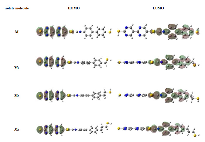
The molecular electronic structure can affect the conductance of the molecular transport junction. As suggested by Cohen et al.[31], the density distribution of frontier molecular orbital is intrinsic to the molecule rather than to the junction. It is an important factor determining the conductance of the molecular transport junction. Therefore, the electronic structures of isolated molecules have been investigated before the electron-transport calculations are performed. Fig. 2 shows the frontier molecular orbital diagrams of the highest occupied molecular orbitals (HOMO) and the lowest unoccupied molecular orbitals (LUMO). The orbital density distributions of HOMO and LUMO for all the molecules are not fully delocalized. Their orbital densities of HOMO are similar and all located on left side of the molecule, and those of LUMO on the molecular right side. Then the phenomenon of resonant tunneling[18] comes into being. The LUMO
Figure 2
Figure 2.
Frontier molecular orbital shapes of HS-BPM-Au(I)CN-BP-SH and its derivatives
exhibits some obvious differences. The density distributions are mainly delocalized on Au(I)CN-BP-SH of isolate molecule M. For isolate molecules M1 to M3, the density distributions are mainly delocalized on Au(I)CN-BP. There is no orbital density distribution on -CH2, -(CH2)2, -(CH2)3 and -SH groups, except the -SH group in M1. So, with increasing the length of alkyl-chain, the phenomenon of resonant tunneling gets weaker. And the LUMO of molecule M distributes a broader range than M1~M3, which is more beneficial to the electronic transportation.
3.2
I-V Characteristics and rectification
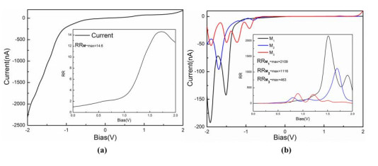
The current-voltage (I-V) curves of the four two-probe systems M to M3 are plotted in Fig. 3. It is evident that the I-V curves of M to M3 are obviously asymmetric at zero bias, and they show more obvious p-n junction characteristics than system M. So the rectification ratios (RR) of molecular systems M1 to M3 are all over 30 times larger than that of system M. The current of model M increases slowly at positive bias and before about –0.5 V at negative bias voltage, and grows rapidly after about –0.5 V. The introducing groups of -CH2, -(CH2)2 and -(CH2)3 into the S-BPM-Au(I)CN-BP-S molecule have obvious effects on the current at –2.0 to +2.0 V bias voltage. The current values of systems M1 to M3 are smaller than those of system M whether at positive or negative bias, but don΄t regularly decrease with increasing the number of alkyl groups in the model molecule, which are different from the Au/S-PBTDT-(CH2)nCH=N-S/Au[4] perhaps because of alkyl groups in the PBTDT-CH=N molecule as bridges. The current value of system M1 grows rapidly after about –1.0 V, which indicates that its forward threshold voltage (–1.0V) is higher than that of system M (–0.5 V). The current values of systems M2 and M3 grow after about –0.7 V, which indicates that its forward threshold voltage (–0.7 V) is also higher than that of system M (–0.5 V). And M3 has bigger current than both M1 and M2 from about –1.5 to –0.8 V. Systems M1 to M3 exhibit obvious negative differential resistance behavior (NDR). With the increased number of alkyl groups in the model molecule, NDR becomes more and more frequent.
Figure 3
Figure 3.
(a) I-V curve of system M in the bias range from –2.0 to +2.0 V, (b) I-V curves of systems M1-M3 in the bias rangefrom –2.0 to +2.0 V. The positive current means that the current flows from the left electrode to the right electrode and vice versa. The inset shows the rectification ratio (RR) as a function of applied voltage for systems M to M3
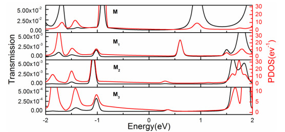
The transmission coefficients of M~M3 two-probe systems and the partial density of states (PDOS) of the M to M3 central molecules under zero bias have been analyzed and give insights into the states contributing to conductivity in Fig. 4. The similarity in the peak structures of PDOS and the transmission spectra indicate a clear corresponding between the energy levels on the central molecules and the transmission spectra. There are two transmission peaks near the Fermi energy in the M system, which is in line with the HOMO and LUMO of thiol-ended BPM-Au(I)CN-BP. At the zero bias, the electron transmission mainly depends on the size of transmission coefficient near the Fermi level. The size of transmission peaks decrease as the alkyl chain grows except that in line with the HOMO of system M1. The size of transmission peak of system M1 in line with the HOMO is smaller than that of system M2. This means electrons cannot permeate effectively through the alkyl chain. According to the current depending on their transmission peaks and coefficients, M1 to M3 systems have smaller current values than M as the applied bias voltage exceeds the forward threshold voltage, in line with the I-V curves. In a word, the tail-doping with alkyl groups reduces the conductivity of the thiol-ended BPM-Au(I)CN-BP.
Figure 4
Figure 4.
Transmission spectra (black lines) and corresponding PDOS spectra (red lines) of the M to M3 two-probe systems under zero bias
In Fig. 3, it is evident that the I-V curves of molecular systems M to M3 are obviously asymmetric at about zero bias. In order to reveal the features of the asymmetry in detail, the rectification ratios of systems M to M3 have been analyzed. The rectification ratio is defined as
$ R(V)=\left|\frac{I(-V)}{I(+V)}\right| $
(2)
By definition, R(V) = 1 means that there is no rectification. R(V) > 1 means that the current is larger in the negative direction than in the positive direction, and vice versa.
According to asymmetric I-V curves, it shows that models M to M3 have obvious rectification effects. Their rectification values are up to 14.6, 2109, 1116 and 463 respectively, as shown in the inset in Fig. 3. It comes out that the modified alkyl groups have many effects on the thiol-ended BPM-Au(I)CN-BP rectification.
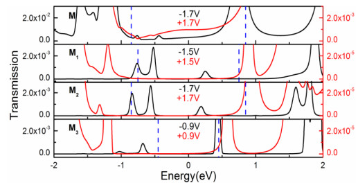
In this work, the rectifying for the molecular systems is interpreted by analyzing the transmission spectra. The current through a molecule system is determined by the transmission spectra within the bias window [μL(Vb), μR(Vb)]. The region of the bias window is actually [–Vb/2, +Vb/2] if the Fermi level is set to zero. Theoretically, the transmission is determined by the molecular electronic structure modified by the applied bias, the coupling between molecule and electrode, etc. Fig. 5 illustrates the transmission spectra of the two-probe systems M~M3 in the energy range from –2 to +2 eV at their bias voltages of the highest rectification ratios.
Figure 5
Figure 5.
Transmission spectra of two-probe systems M to M3 at special bias of each highest rectification ratio. Red, black and bluedashed lines indicate the positive bias voltage, negative bias voltage and bias windows at each bias voltage, respectively
It is noted that transmission spectra of systems M~M3 exhibit a very large difference at positive and negative bias voltages. The transmission resonance peaks within each bias window of systems M~M3 at negative bias are much higher than those at the positive bias. In system M, applied by the negative bias voltage, there are three peaks within the bias window. One originates from LUMO, and the other two from HOMO and HOMO-1. Applied by the positive bias voltage, a broad peak originates from LUMO within the bias window. From the diagram of M in Fig. 5, the transmission coefficient under –1.7 V is 10 times that at +1.7 V, so the integral area of transmission peak at –1.7 V is about 15 times larger than that at +1.7 V. The negative current is about 15 times that of the forward current at 1.7 V because it is determined by the integral area of transmission peak of the bias window. For M1 to M3 systems, the transmission coefficient under negative bias voltage is 100 times that under positive bias voltage. Applied by the positive bias voltage for three systems, there is a peak originating from LUMO, and a small part of it enters in the bias window, so the current of three systems is very little at the positive bias. According to the extent to which the peak is in the bias window, the integral area in systems M3 is slightly bigger than that in M1, and the integral area in M2 is about 3 times than that in system M1 under positive bias. Then the current of M2 is relatively the largest and that of M1 is the smallest at the positive bias. In systems M1 and M2, there are two complete peaks and one half peak in the bias window under negative bias, one complete peak originates from HOMO, half peak originates from HOMO-1 and another one complete peak from LUMO. In system M3, there is one half peak originating from LUMO in the bias window under the negative bias. The integral area is the smallest in system M3, and the integral area in system M2 is nearly equal to that in system M1 under negative bias. Lastly, it can be concluded that the rectifier ratio of M1 system at 1.5 bias voltage is the largest among three systems.
4.
CONCLUSION
Introducing alkyl groups into the BPM-Au(I)CN-BP molecule has significantly obvious effects on the current at –2.0 to +2.0 bias voltage. The currents of molecular junctions M1, M2 and M3 are much lower than that of system M. Systems M1 to M3 exhibit obvious negative differential resistance behavior. Rectifying performance of Au/S-BPM-Au(I)CN-BP-S/Au molecular junction can be regulated by introducing alkyl chain. The Au/S-BPM-Au(I)CN-BPCH2-S/Au molecular junction (M1) exhibits the best rectifying effect. Its maximum rectifying ratio is 2109, which is about 150 times more than that of the molecular junction based on the original BPM-Au(I)CN-BP.
[1]
Wong, H.; Iwai, H. The road to miniaturization. Phys. World2005, 9, 40−42.
[2]
Moore, G. E. Cramming more components onto integrated circuits. Electron.1965, 8, 114−117.
[3]
Feynman, R. P. There΄s plenty of room at the bottom. Eng. Sci.1960, 5, 22−36.
[4]
Chen, Z.; Zhang, Y.; Guo, Z.; Lin, L.; Yang, E.; Ling, Q. The first principle study on the rectification of molecular junctions based on the alkyl-chain-modified phenyl benzothiophene derivative. Chin. J. Struct. Chem.2018, 7, 1037−1044.
[5]
Sun, Y.; Chen, S.; Chen, X.; Xu, Y.; Zhang, S.; Ou, Y.; Yang, G.; Li, H. A highly selective and recyclable NO-responsive nanochannel based on a spiroring opening-closing reaction strategy. Nat. Commun.2019, 10, 1323−1330. doi: 10.1038/s41467-019-09163-4
[6]
Wang, M.; Meng, H.; Wang, D.; Yin, Y.; Stroeve, P.; Zhang, Y.; Sheng, Z.; Chen, B.; Zhan, K.; Huo, X. Dynamic curvature nanochannel-based membrane with anomalous ionic transport behaviors and reversible rectification switch. Adv. Mater.2019, 11, 1805130−9.
[7]
Metzger, R. M. Unimolecular electrical rectifiers. Chem. Rev.2003, 9, 3803−3834.
[8]
Kubatkin, S.; Danilov, A.; Hjort, M.; Cornil, J.; Brédas, J. L.; Stuhr-Hansen, N.; Hedegård, P.; Bjórnholm, T. Single-electron transistor of a single organic molecule with access to several redox states. Nature2003, 6956, 698−701.
Joshi, A.; Ramachandran, C. N. High-bias negative differential resistance effect in pure, doped and co-doped carbon nanotubes connected to boron nitride nanotubes. Phys. E: Amsterdam, Neth. 2019, 113, 1−7. doi: 10.1016/j.physe.2019.04.021
[11]
Wei, M.; Fu, X.; Wang, Z.; Hu, G.; Li, Z.; Wang, C.; Zhang, G. Bias and molecular-length dependent odd-even effect of rectification in 4΄-methyl-2΄-bipyridyl-terminated n-alkanethiolate single-molecule diodes. J. Mater. Chem. C2019, 29, 9000−9007.
[12]
Tanaka, Y.; Kiguchi, M.; Akita, M. Inorganic and organometallic molecular wires for single-molecule devices. Chem. -Eur. J.2017, 20, 4741−4749.
[13]
Song, A. M.; Lorke, A.; Kriele, A.; Kotthaus, J. P.; Wegscheider, W.; Bichler, M. Nonlinear electron transport in an asymmetric microjunction: a ballistic rectifier. Phys. Rev. Lett.1998, 17, 3831−3834.
[14]
Deng, Y.; Chen, S.; Zeng, Y.; Zhou, W.; Chen, K. Large spin rectifying and high-efficiency spin-filtering in superior molecular junction. Org. Electron. 2017, 50, 184−190. doi: 10.1016/j.orgel.2017.07.046
[15]
Yuan, S.; Dai, C.; Weng, J.; Mei, Q.; Ling, Q. Wang, L.; Huang, W. Theoretical studies of electron transport in thiophene dimer: effects of substituent group and heteroatom. J. Phys. Chem. A2011, 17, 4535−4546.
[16]
Kala, C. P.; Thiruvadigal, D. J. First-principles study of electron transport in azulene molecular junction: effect of electrode material on electrical rectification behavior. J. Comput. Electron.2018, 2, 580−585.
[17]
Garg, K.; Majumder, C.; Gupta, S. K.; Aswal, D. K.; Nayak, S. K.; Chattopadhyay, S. A novel design for porphyrin based D–s–A systems as molecular rectifiers. Chem. Sci.2016, 2, 1548−1557.
[18]
Zhao, P. J.; Cui, H. L.; Woolard, D.; Jensen, K. J.; Buot, F. A. Simulation of resonant tunneling structures: origin of the I-V hysteresis and plateau-like structure. J. Appl. Phys.2000, 3. 1337−1349.
[19]
Seki, T.; Kurenuma, S.; Ito, H. Luminescence color-tuning through polymorph doping: preparation of a white-emitting solid from a single gold(I)-isocyanide complex by simple precipitation. Chem. -Eur. J.2013, 48, 16214−16220.
[20]
Sathyanarayana, A.; Nakamura, S.; Hisano, K.; Tsutsumi, O.; Srinivas, K.; Prabusankar, G. Controlling the solid-state luminescence of gold(I) N-heterocyclic carbene complexes through changes in the structure of molecular aggregates. Sci. Chi. Chem.2018, 8, 957−965.
[21]
Yuan, S.; Wang, S.; Mei, Q.; Lin, Q.; Wang, L.; Huang, W. First-principles study of rectification in bis-2-(5-ethynylthienyl) ethyne molecular junctions. J. Phys. Chem. A2011, 32, 9033−9042.
[22]
George, C. B.; Ratner, M. A.; Lambert, J. B. Strong conductance variation in conformationally constrained oligosilane tunnel junctions. J. Phys. Chem. A2009, 16, 3876−3880.
[23]
Frisch, M. J.; Trucks, G. W.; Schlegel, H. B.; Scuseria, G. E.; Robb, M. A.; Cheeseman, J. R.; Montgomery, J. A.; Vreven, Jr. T.; Kudin, K. N.; Burant, J. C.; Millam, J. M.; Iyengar, S. S.; Tomasi, J.; Barone, V.; Mennucci, B.; Cossi, M.; Scalmani, G.; Rega, N.; Petersson, G. A.; Nakatsuji, H.; Hada, M.; Ehara, M.; Toyota, K.; Fukuda, R.; Hasegawa, J.; Ishida, M.; Nakajima, T.; Honda, Y.; Kitao, O.; Nakai, H.; Klene, M.; Li, X.; Knox, J. E.; Hatchian, P.; Cross, J. B.; Bakken, V.; Adamo, C.; Jaramillo, J.; Gomperts, R.; Stratmann, R. E.; Yazyev, O.; Austin, A. J.; Cammi, R.; Pomelli, C.; Ochterski, J. W.; Ayala, P. Y.; Morokuma, K.; Voth, G. A.; Salvador, P.; Dannenberg, J. J.; Zakrzewski, V. G.; Dapprich, S.; Daniels, A. D.; Strain, M. C.; Farkas, O.; Malick, D. K.; Rabuck, A. D.; Raghavachari, K.; Foresman, J. B.; Ortiz, J. V.; Cui, Q.; Baboul, A. G.; Clifford, S.; Cioslowski, J.; Stefanov, B. B.; Liu, G.; Liashenko, A.; Piskorz, P.; Komaromi, I.; Martin, R. L.; Fox, D. J.; Keith, T.; Al-Laham, M. A.; Peng, C. Y.; Nanayakkara, A.; Challacombe, M.; Gill, P. M. W.; Johnson, B.; Chen, W.; Wong, M. W.; Gonzalez, C.; Pople, J. A. Gaussian 03, Revision D. 01. Gaussian, Inc. : Wallingford CT 2004.
[24]
Becke, A. D. A new mixing of hartree-fock and local density functional theories. J. Chem. Phys.1993, 2, 1372−1377.
[25]
Lee, C.; Yang, W.; Parr, R. G. Development of the colle-salvetti correlation-energy formula into a functional of the electron density. Phys. Rev. B1988, 37, 785−789. doi: 10.1103/PhysRevB.37.785
[26]
Yin, X.; Li, Y.; Zhang, Y.; Li, P.; Zhao, J. Theoretical analysis of geometry-correlated conductivity of molecular wire. Chem. Phys. Lett.2006, 422, 111−116. doi: 10.1016/j.cplett.2006.02.020
[27]
Brandbyge, M.; Mozos, J.; Ordejon, P.; Taylor, J.; Stokbro, K. Density-functional method for nonequilibrium electron transport. Phys. Rev. B2002, 65, 165401−17.
Hu, Y.; Zhu, Y.; Gao, H.; Guo, H. Conductance of an ensemble of molecular wires: a statistical analysis. Phys. Rev. Lett.2005, 95, 156803−4.
[30]
Soler, J. M.; Artacho, E.; Gale, J. D.; Garcia, A.; Junquera, J.; Ordejon, P.; Sanchez Portal, D. The SIESTA method for ab initio order-N materials simulation. J. Phys: Condens. Matter.2002, 14, 2745−2779.
[31]
Coben, R.; Stokbro, K.; Martin, J. M. L.; Ratner, M. A. Charge transport in conjugated aromatic molecular junctions: molecular conjugation and molecule-electrode coupling. J. Phy. Chem. C2007, 111, 14893−14902.
Figure 1
Schematic view of the two-probe Au/S-BPM-Au(I)CN-BPCH2-S/Au molecular junction (M1); The central moleculeBPM-Au(I)CN-BPCH2 replaced by BPM-Au(I)CN-BP, S–BPM-Au(I)CN-BP(CH2)2 and BPM-Au(I)CN-BP(CH2)3 is Corresponding to M, M2 and M3 molecular junctions, respectively. These thiolate-ended molecules self-assemble on the Au(111)-(3×3)surface, and consist of the two-probe Au/molecule/Au systems with right and left semi-infinite electrodes and the scattering region
Figure 3
(a) I-V curve of system M in the bias range from –2.0 to +2.0 V, (b) I-V curves of systems M1-M3 in the bias rangefrom –2.0 to +2.0 V. The positive current means that the current flows from the left electrode to the right electrode and vice versa. The inset shows the rectification ratio (RR) as a function of applied voltage for systems M to M3
Figure 5
Transmission spectra of two-probe systems M to M3 at special bias of each highest rectification ratio. Red, black and bluedashed lines indicate the positive bias voltage, negative bias voltage and bias windows at each bias voltage, respectively

 DownLoad:

 下载:
下载:


 下载:
下载:
