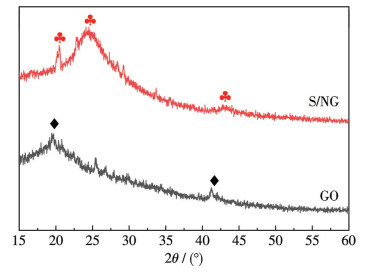
Figure 1.
XRD patterns of GO and S/NG

S/N co-doped graphene-decorated double perovskite La0.6Sr1.4Ni0.4Co1.6O6 as an efficient bifunctional oxygen electrocatalyst
Qiuting HUANG , Chenhui WEI , Hongxia HUANG , Houqing ZHOU , Xiaodong TANG , Jieyu LIANG


Due to the ever-growing impact of carbon pollution on the global climate and environment, the development of new clean energy sources has become a priority for the future[1]. The most promising energy conversion processes involve various basic electrochemical redox reactions, such as the hydrogen evolution reaction (HER), oxygen evolution reaction (OER), and oxygen reduction reaction (ORR)[2-3]. The sluggish kinetics of OER and ORR result in high overpotentials, which significantly reduce the overall energy conversion efficiency[4-5]. Consequently, numerous highly efficient OER/ORR catalysts are being developed to overcome this bottleneck[6]. Platinum, iridium, and their oxides show excellent catalytic properties for OER and ORR. However, the high cost and scarcity have limited their large-scale commercialization. Therefore, the development of ORR/OER catalysts with high activity, low cost, abundant reserves, and good stability has become a research focus[7-10]. Perovskite oxides exhibit the advantages of low price, facile preparation, and excellent stability in alkaline electrolyte, and have become a promising substitute for precious metal catalysts[11]. The general formula for a simple perovskite oxide is ABO3, in which the A-site is typically occupied by a rare-earth or alkaline-earth metal element, such as Ca, Sr, or Ba. The B-site is generally occupied by a transition metal element, such as Ti, Mn, Fe, or Co. These B-site elements play a crucial role in determining the properties of perovskite materials due to their ability to adopt multiple valence states[12-16]. Double perovskite oxides, generally represented as AA′B2O6 or A2BB′O6, are characterized by ordered arrangements of octahedra in layered, rock-salt, or columnar configurations. However, most perovskites have low electrical conductivity at room temperature, thus hindering the electrocatalytic activity. In addition, during the sol-gel preparation, perovskite particles tend to agglomerate, which reduces their specific surface area and consequently impairs the catalytic performance. Combining perovskites with other materials can achieve synergistic catalytic effects, enhancing both electrocatalytic performance and stability.
Recent research has shown that carbon-based materials exhibit superior electrocatalytic activity for both ORR and OER[17]. Carbon materials can facilitate electron transfer, suppress the volume expansion of active materials, and modulate the interfacial contact between reaction intermediates and active sites[18]. Among them, graphene has attracted significant attention due to its excellent electrical conductivity, high surface area, strong adhesion to catalyst particles, and good chemical and environmental stability[19]. As a typical metal-free carbon-based catalyst, graphene relies on its designable edges and defect-related active sites to facilitate electrochemical reactions[20]. Nevertheless, graphene sheets are prone to aggregate into graphite-like structures due to the van der Waals forces between individual layers, resulting in a sharp reduction in specific surface area and compromised ion transport kinetics, which ultimately degrades the electrocatalytic performance. To mitigate aggregation of graphene and facilitate rapid ion and electron transfer, various innovative graphene architectures have been developed[21]. Heteroatoms can modulate the charge density and electronic structure of carbon materials, rendering heteroatom doping an effective strategy to significantly improve catalytic activity. Doping graphene with heteroatoms particularly enhances the electrocatalytic process for ORR: the highly electronegative nitrogen atoms induce electron transfer from carbon atoms, thereby enhancing the adsorption capacity for ORR intermediates and electrical conductivity. Meanwhile, doping of S atoms can create an uneven spin-density distribution to regulate the electronic structure[22-24].
Ran et al.[25] improved electrical conductivity in LaCoO3 perovskite oxide through sulfur doping with varying ratios, obtaining a Tafel slope of 126.7 mV·dec-1. It confirms that modulating the electronic state of perovskite oxides via sulfur doping is an effective strategy for constructing high-performance electrocatalysts. Wei et al.[26] combined nitrogen-doped graphene at different mass ratios with La0.4Sr0.6Co0.8Ni0.2O3, enhancing the electrocatalytic performance of the perovskite. Their 10% N-G hybrid catalyst achieved a Tafel slope of 122.8 mV·dec-1, and the lower electron transfer resistance of the oxygen electrode demonstrated excellent catalytic activity for ORR/OER. Li et al.[27] demonstrate that coating sulfur/nitrogen co-doped graphene on graphite felt can increase the effective surface area and introduce active functional groups for vanadium redox reactions, significantly improving the energy efficiency, discharge capacity, and cycling capacity retention of vanadium redox flow batteries.
So far, there have been few reports on the application of S/N co-doped graphene to enhance the ORR/OER electrocatalytic performance of perovskite oxides[28-31]. Herein, a S/N co-doped graphene (named as S/NG) was synthesized and combined with the double perovskite oxide La0.6Sr1.4Ni0.4Co1.6O6 (marked as LSNC) to obtain a composite bifunctional electrocatalyst (LSNC@S/NG). The electrocatalytic performance of the catalysts was extensively evaluated.
All chemical reagents used in this experiment were purchased from Xilong Chemical, while acetylene black and carbon black were obtained from the Lizhiyuan Battery Sales Department.
LSNC was synthesized via a sol-gel method using citric acid monohydrate as a complexing agent. Stoichiometric amounts of the corresponding metal nitrates were dissolved in deionized water. Then citric acid monohydrate was added to the solution with three times the total amount (amount of substance) of metal ions. Aqueous ammonia was later added to adjust the solution′s pH to 2.0. The mixture was stirred continuously and heated to 80 ℃ using a constant-temperature magnetic stirrer until the water evaporated and a transparent gel formed. The transparent gel was dried and pre-calcined for 30 min, and then the precursor was ground and sintered at 800 ℃ for 4 h to yield the desired perovskite oxide LSNC.
Graphene oxide (GO) was prepared as follows: first, a mixture of 1 g of graphite powder and 23 mL of concentrated sulfuric acid (H2SO4, 98%) was cooled in an ice-water bath (0-5 ℃) for 10 min. Then, 0.5 g of potassium nitrate (KNO3) was introduced, and the mixture was stirred for 30 min to ensure uniform mixing. Subsequently, 4.5 g of potassium permanganate (KMnO4) was slowly added to avoid local overheating, and stirring was continued for a further 0.5 h while maintaining the ice-water bath throughout. The temperature of the mixture was raised to 35 ℃, and 63 mL of deionized water was added dropwise under continuous stirring to prevent sudden boiling. The temperature was further raised to 98 ℃ and maintained for 30 min to promote the oxidation reaction. After the reaction, 1.4 mL of hydrogen peroxide (H2O2, 30%) was added to reduce residual KMnO4 to soluble Mn2+, and the mixture was stirred for 10 min to ensure complete reaction. The mixture was then allowed to settle for 5 min. Finally, the resulting product was centrifuged at 8 000 r·min-1 for 10 min and repeatedly washed with 1 mol·L-1 HCl (to remove metal ion impurities) and deionized water until a neutral pH (≈7.0). The washed product was freeze-dried for 24 h to obtain GO.
The preparation process of S/NG was as follows: first, 0.05 g of GO was dispersed in 50 mL of deionized water. The mixture was subjected to ultrasonication until completely exfoliated, resulting in a homogeneous GO dispersion with a mass concentration of 1 mg·mL-1. Subsequently, 0.3 g of thiourea was gradually added to the GO solution under continuous stirring. The resulting mixture was further subjected to ultrasonic dispersion in an ice-water bath for 30 min, followed by stirring for 2 h. S/NG was obtained by conducting a hydrothermal reaction of the product at 180 ℃ for 12 h, followed by centrifuge washing and freeze-drying for 48 h[32].
S/NG, with mass fractions of 5%, 10%, 15%, and 20% relative to the total composite catalyst mass, was dispersed in anhydrous ethanol, and the mixture was subjected to ultrasonic treatment for 30 min to form a homogeneous suspension. The corresponding mass of LSNC was introduced into the mixture and ultrasonicated for 1 h. The resulting mixture was transferred to an agate pot and ball-milled for 0.5 h, followed by ultrasonic treatment for another 0.5 h. After the ethanol was evaporated off in a water bath at 80 ℃, the product was dried at 60 ℃ to obtain the final composite catalyst LSNC@S/NG. The hybrid catalysts based on mass fractions of 5%, 10%, 15%, and 20% of S/NG were designated as LSNC@S/NG-5%, LSNC@S/NG-10%, LSNC@ S/NG-15%, and LSNC@S/NG-20%, respectively.
The catalyst, polytetrafluoroethylene (PTFE) suspension (mass fraction: 60%), and carbon black (Vulcan XC-72R) in a mass ratio of 1∶1∶2 were added to an isopropyl alcohol solution. The mixture was ball-milled for 30 min at a rotational speed of 300 r·min-1 and ultrasonically treated at room temperature for 0.5 h to ensure homogeneity. The obtained mixed solution was heated in a water bath at 80 ℃ and then evaporated until an elastic mass was formed. The lumps were pressed into 0.32 mm-thick films by using a roller press and dried overnight in an oven at 60 ℃ to obtain the catalytic layer. A waterproof layer (thickness of 0.55 mm) was composed of acetylene black and PTFE suspension (mass fraction: 60%) in a mass ratio of 7∶3, following the same procedure as used for the catalytic layer. The catalytic layer (area: 1.44 cm2), nickel mesh current collector (area: 3.15 cm2), and waterproof layer (area: 1.69 cm2) were assembled and compacted into electrode sheets by a tablet press at 18 MPa for 30 s. Finally, the electrode was heat-treated in a muffle furnace at 340 ℃ for 0.5 h to remove residual organic solvents, yielding the final oxygen electrode. The resulting oxygen electrode was subsequently cut to an area of 1.00 cm2 for testing. The catalyst loading was determined by weighing to be approximately 5.7 mg·cm-2.
The working electrode for RDE measurements was prepared as follows: the as-prepared catalyst (5 mg) was dispersed in a mixed solvent of Nafion (10 μL) and N,N-dimethylformamide (1 mL) under ultrasonication to form a homogeneous slurry, which was then drop-cast onto the glassy carbon electrode using a micropipette.
The crystal structure of the samples was characterized by a PANalytical XPERT-3 diffractometer using Cu Kα radiation (λ=0154 06 nm) at 40 kV and 40 mA. Data were collected over a 2θ range of 10°-80° with a step size of 0.026 26° in continuous scanning mode. The surface morphology and elemental composition of the samples were observed by a SU5000 scanning electron microscope (SEM, Hitachi) operated at an accelerating voltage of 5 kV. The nitrogen adsorption-desorption measurements were determined at 77 K using N2 as the adsorbate on a Micromeritics TB440A instrument (USA), and the Brunauer-Emmett-Teller (BET) method was applied for surface area calculation. X-ray photoelectron spectroscopy analysis was carried out on a Thermo Scientific K-Alpha spectrometer using monochromatic Al Kα radiation as the excitation source, with the operating voltage set to 15 kV and the emission current adjusted to 10 mA. The spectra were recorded with a step size of 0.05 eV and a dwell time of 0.5 s per step.
All electrochemical measurements were performed on a CHI660E electrochemical workstation (Chenhua, Shanghai) at room temperature and under ambient pressure, using a conventional three-electrode system. The working electrode was an oxygen electrode with a geometric area of 1 cm2. A Hg/HgO electrode and a platinum electrode were employed as the reference electrode and the counter electrode, respectively. In the polarization tests, the potential ranges for anodic polarization (OER) and cathodic polarization (ORR) were 0-1.0 V (vs Hg/HgO) and 0-0.6 V (vs Hg/HgO) with a scan rate of 3 mV·s-1. The electrical double-layer capacitance (Cdl) was determined by cyclic voltammetry (CV) at various scan rates ranging from 20 to 120 mV·s-1 within a potential window of 0.15-0.25 V. In the electrochemical impedance spectroscopy (EIS) measurements, the frequency range was set from 1 Hz to 100 kHz with an amplitude of 5 mV. To investigate the electron-transfer mechanism of ORR, linear sweep voltammetry (LSV) was performed using a rotating disk electrode (RDE, geometric area: 0.125 cm2) at rotation speeds of 400, 800, 1 200, 1 600, and 2 000 r·min-1. The electrolyte was 0.1 mol·L-1 KOH saturated with O2, and the potential was swept from -1.4 to 0 V at a scan rate of 0.02 V·s-1. The resulting currents were then normalized by the electrode′s geometric area to obtain current densities.
In the subsequent results and discussion section, all potentials have been converted to the reversible hydrogen electrode (RHE) scale.
X-ray diffraction (XRD) was employed to characterize the crystal structures of GO and S/NG. As shown in Fig.1, GO displayed a strong diffraction peak at 2θ≈19.36° and a weak peak at 2θ≈41.07°, corresponding to the (001) and (100) crystal planes, respectively[33]. In contrast, S/NG displayed a broad diffraction peak centered at 2θ≈24.5°, along with a residual peak near 20.19°—a feature resembling that observed in GO. Additionally, a diffraction peak appeared at around 42.67° in the S/NG. This broadening and shift of the diffraction peak suggest a reduction in structural ordering and potential lattice distortion, likely resulting from the decreased oxidation degree of graphene and the incorporation of heteroatoms (S and N), which disrupts the AB stacking sequence of the graphitic layers[32].
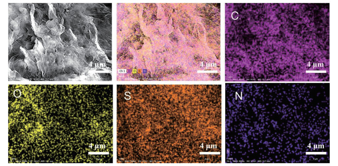
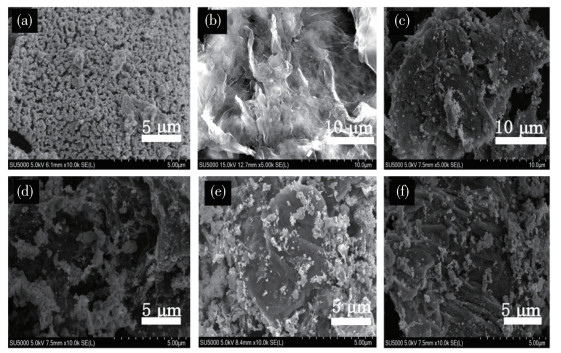
The morphologies of LSNC and LSNC@S/NG are characterized by SEM. As observed in Fig. 2a, the LSNC catalyst particles exhibited a relatively small size and uniform distribution, although partial agglomeration was noted. S/NG (Fig. 2b) displayed a folded and porous network structure, providing a large effective contact area and facilitating the formation of abundant active sites for the anchoring of perovskite oxide particles. Fig. 2c-2f illustrate that the LSNC particles were uniformly distributed on the surface of S/NG. However, more pronounced agglomeration was observed in the LSNC@S/NG-5% and LSNC@S/NG-10% composites (Fig.2c and 2d), which may be attributed to the relatively low content of S/NG. As the S/NG content increased, the LSNC particles became smaller in the LSNC@S/NG-15% and LSNC@S/NG-20% composites, and the layered structure of S/NG appeared more distinct. As shown in Fig.3, energy-dispersive X-ray spectroscopy (EDS) analysis confirmed the presence of S, N, C, and O elements with a homogeneous distribution, demonstrating the successful incorporation of S and N into the graphene structure. Table 1 summarizes the elemental composition, indicating relatively high contents of C and O, along with lower but detectable amounts of S and N.

 下载:
导出CSV
下载:
导出CSV
| Sample | Mass fraction / % | |||
| S | N | C | O | |
| S/NG | 7.68 | 9.29 | 71.84 | 11.19 |
Table 2 presents the BET specific surface area test results of LSNC, S/NG, and LSNC@S/NG. Carbon-based materials used as electrocatalysts typically exhibit excellent electrical conductivity and a high specific surface area, which contribute to the high dispersion of active sites and facilitate charge transfer during electrocatalytic processes; these properties thereby effectively enhance catalytic performance. The measured specific surface area of pristine LSNC was 8 m2·g-1, while that of S/NG reached 16 m2·g-1. After compounding with S/NG, the specific surface area of the composite catalyst increased significantly. Among the composites, LSNC@S/NG-15% exhibited the largest specific surface area of 11 m2·g-1, which promotes better contact with O and provides more active sites for the reaction. However, when the composite ratio was further increased, the specific surface area of the composite slightly decreased, likely due to agglomeration in the composite material.
下载:
导出CSV
| Parameter | LSNC | S/NG | LSNC@S/NG-5% | LSNC@S/NG-15% | LSNC@S/NG-20% |
| SBET / (m2·g-1) | 8 | 16 | 9 | 11 | 10 |
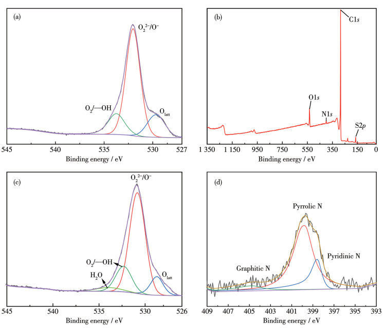
To gain further insight into the surface chemistry of the LSNC@S/NG-15% catalyst, XPS analysis was conducted. As shown in Fig. 4a, the O1s XPS spectrum of LSNC could be deconvoluted into three oxygen species. The peak at 529.6 eV is attributed to lattice oxygen (Olatt), while the peaks at 532.08 and 533.78 eV correspond to highly oxidized oxygen species (O22-/O-) and surface-adsorbed oxygen species (—OH/O2), respectively. Fig.4b displays the XPS survey spectrum of LSNC@S/NG-15%, confirming the presence of C, N, O, and S elements, which further verifies the successful incorporation of S and N into the graphene structure. The O1s spectrum of LSNC@S/NG-15% (Fig.4c) consists of four types of oxygen components: Olatt, highly oxidized oxygen, —OH/O2, and chemisorbed water. According to peak area analysis, the proportion of O22-/O- in LSNC@S/NG-15% (86%) was higher than that in LSNC (82%). This indicates that the synergistic interaction between S/NG and LSNC leads to more oxygen defect sites in the hybrid catalyst. The N1s XPS spectrum of LSNC@S/NG-15% (Fig. 4d) can be fitted into three nitrogen configurations: graphitic N, pyrrolic N, and pyridinic N. Doping N into the carbon matrix can alter the charge/spin density of adjacent C atoms, thereby promoting ORR. In particular, pyridinic N is capable of coordinating with transition metals to form M-Nx-C active sites, which are recognized as highly active ORR catalytic centers[34].
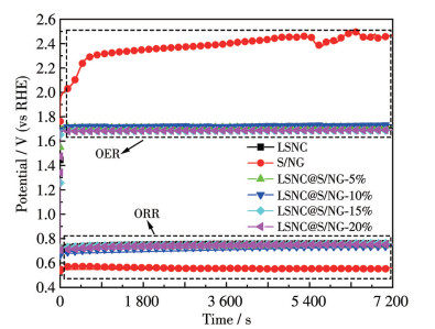
To investigate the stability of the catalytic oxygen electrodes based on LSNC and LSNC@S/NG for both OER and ORR, steady-state galvanostatic tests were conducted at a current density of 50 mA·cm-2 for 7 200 s under anodic mode (OER) and cathodic mode (ORR), respectively, as shown in Fig. 5. From the figure, it can be observed that in the anodic mode, the pristine S/NG exhibited significant potential fluctuations, indicating poor stability, with a steady-state potential as high as 2.46 V. In the cathodic mode, its steady-state potential was 0.5 V, showing a more negative plateau potential than those of the other catalysts. LSNC and LSNC@S/NG exhibited relatively similar stabilities. Specifically, under anodic mode, the steady-state plateau potentials of LSNC@S/NG-15% and LSNC@S/NG-20% were nearly identical and relatively low, at approximately 1.69 V. In the cathodic mode, the steady-state plateau potential of LSNC@S/NG-15% was approximately 0.76 V. Overall, LSNC@S/NG-15% exhibited good catalytic stability.
The anodic LSV curves (Fig. 6a) were recorded for LSNC, S/NG, LSNC@S/NG-5%, LSNC@S/NG-10%, LSNC@S/NG-15%, and LSNC@S/NG-20%. Pristine S/NG catalyst exhibited a current density of 136.2 mA·cm-2 at 1.97 V, indicating significant polarization. In comparison, at the same potential, LSNC@S/NG-5%, LSNC@S/NG-10%, and LSNC@S/NG-20% achieved current densities of 258.4, 272.8, and 305.2 mA·cm-2, respectively. LSNC@S/NG-15% demonstrated the highest current density of 356.0 mA·cm-2, which is attributed to its superior conductivity and ample active sites for the OER.
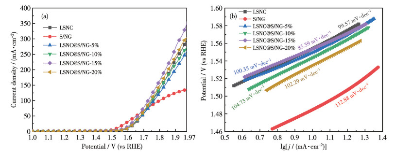
As evidenced by the Tafel plot (Fig. 6b), LSNC@S/NG-15% exhibited a Tafel slope of 85.39 mV·dec-1, substantially lower than those of LSNC (99.57 mV·dec-1), S/NG (112.88 mV·dec-1), LSNC@S/NG-5% (100.35 mV·dec-1), LSNC@S/NG-10% (104.73 mV·dec-1), and LSNC@S/NG-20% (102.29 mV·dec-1), indicating that LSNC@S/NG-15% possessed the most efficient OER kinetics among the tested catalysts. The Tafel slopes were obtained by linear fitting of the polarization curves in the potential range of 1.46-1.58 V, where a well-defined linear relationship was observed for all catalysts. The incorporation of N and S dopants not only offers additional active sites but also promotes the formation of a dense protective layer on the perovskite particle surfaces[35]. Such a coating effectively inhibits particle dissolution and aggregation during operation, thereby significantly improving the electrocatalytic performance for OER[36].
Fig. 7a shows the cathodic LSV curves of the oxygen electrodes based on LSNC, S/NG, LSNC@S/ NG-5%, LSNC@S/NG-10%, LSNC@S/NG-15%, and LSNC@ S/NG-20%. The limiting current density of the pristine S/NG catalyst was only 86.3 mA·cm-2 at the potential of 0.37 V. The limiting current densities of LSNC, LSNC@S/NG-5%, LSNC@S/NG-10%, LSNC@ S/NG-15%, and LSNC@S/NG-20% were 270.3, 247.0, 248.7, 300.4, and 280.9 mA·cm-2, respectively, indicating that LSNC@S/NG-15% exhibited the best ORR catalytic performance among the tested series.
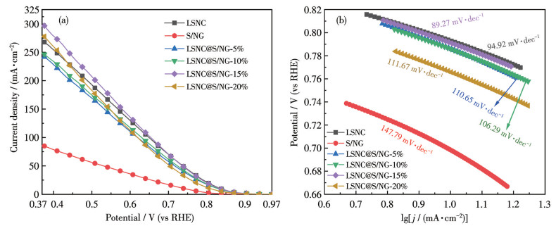
It can be seen from Fig. 7b that the Tafel slopes of LSNC, S/NG, LSNC@S/NG-5%, LSNC@S/NG-10%, LSNC@S/NG-15%, and LSNC@S/NG-20% were 94.92, 147.79, 110.65, 106.29, 89.27, and 111.67 mV·dec-1, respectively. Linear fitting of the polarization curves within the potential window of 0.66-0.82 V was performed to extract the Tafel slopes, and all catalysts exhibited a well-defined linear relationship in this region. The result demonstrates that LSNC@S/NG-15% exhibited the most favorable kinetics for the ORR compared to other composites. Study reveals that the chemical states of heteroatoms and carbon atoms create a synergistic effect by modulating charge and spin densities, thereby collectively boosting the ORR performance[37].
To further investigate the catalytic activity, the electrochemically active surface areas (ECSA) of LSNC, S/NG, LSNC@S/NG-5%, LSNC@S/NG-10%, LSNC@S/NG-15%, and LSNC@S/NG-20% catalysts were evaluated by measuring the Cdl via CV. As shown in Fig. 8, the Cdl of LSNC@S/NG-15% was 71.14 mF·cm-2, which was significantly higher than those of LSNC (27.54 mF·cm-2), S/NG (14.36 mF·cm-2), LSNC@S/NG-5% (66.10 mF·cm-2), LSNC@S/NG-10% (66.40 mF·cm-2), and LSNC@S/NG-20% (70.50 mF·cm-2). A higher Cdl corresponds to a larger ECSA. The notably large ECSA of LSNC@S/NG-15% is expected to enhance the reaction activity by providing more efficient triple-phase regions for electrocatalytic reactions. These findings are consistent with the BET and LSV results discussed earlier. Heteroatom doping (e.g., S, N, P, and O) in the carbon framework has been shown to improve electron transfer efficiency, while the introduction of electroactive sites can enhance adsorption capacity and reaction kinetics. Consequently, the synergistic effect of tailored structural design and strategic surface modification effectively improves the energy storage performance of carbon-based materials[38].
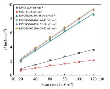
Fig. 9 shows the EIS Nyquist plots of LSNC, S/NG, and LSNC@S/NG-15% oxygen electrodes. The spectra typically consisted of two distinct regions: a high-frequency semicircle, corresponding to charge-transfer resistance (with a larger diameter indicating higher resistance), and a low-frequency sloping line associated with the diffusion process. It can be observed that the semicircle diameters follow the order: S/NG > LSNC > LSNC@S/NG-15%, indicating the lowest charge-transfer resistance (Rct) and the best conductivity of the LSNC@S/NG-15% oxygen electrode. The impedance spectrum was fitted using ZsimDemo software, and the fitting results are summarized in Table 3. In the equivalent circuit model employed, the symbols L, Rs, Rct, Cd, and Q represent the inductance, electrolyte solution resistance, charge transfer resistance, capacitance, and constant phase element, respectively. As shown in Table 3, LSNC@S/NG-15% displayed the smallest Rct, confirming its superior catalytic performance among the tested electrodes.
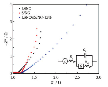
Inset: equivalent circuit diagram.
下载:
导出CSV
| Sample | Rs / Ω | Cd / mF | Rct / Ω |
| LSNC | 1.047 | 4.405 | 0.113 |
| S/NG | 1.203 | 0.149 4 | 0.343 |
| LSNC@S/NG-15% | 1.102 | 5.201 | 0.112 |
The ORR performance and electron-transfer pathway were further investigated using LSV with an RDE. The electron transfer number (n) was calculated using the Koutecký-Levich (K-L) equation[39]:
|
|
(1) |
|
|
(2) |
|
|
(3) |
|
|
(4) |
where, j is the measured current density (mA·cm-2), jK is the kinetic current density (mA·cm-2), jL is the limiting diffusion current density (mA·cm-2), n is the electron transfer number, F is the Faraday constant (96 485 C·mol-1), ω is the rotation speed (rad·s-1), k is the oxygen reduction rate constant (cm·s-1),
To evaluate the electron transfer pathway of the catalysts for the ORR, the RDE technique was employed to perform LSV measurements on LSNC, S/NG, and LSNC@S/NG-15% catalysts at different rotation speeds (400, 600, 900, 1 225, 1 600 r·min-1) as shown in Fig.10. The inset shows the linear plots of j-1 versus ω-1/2 in the potential range of 0.30-0.50 V derived from the K-L equation and the LSV curves. Comparison of the polarization curves at 1 225 r·min-1 revealed that the LSNC@S/NG-15% catalyst exhibited an onset potential of 0.863 V and a half-wave potential of 0.715 V, both higher than those of LSNC (onset potential: 0.858 V, half-wave potential: 0.598 V) and S/NG (onset potential: 0.811 V, half-wave potential: 0.649 V). A higher half-wave potential indicates a lower overpotential and higher energy efficiency. For comparison, the commercial Pt/C catalyst showed an onset potential of 0.89 V and a half-wave potential of 0.83 V, both higher than those of the as-prepared catalysts[40-41]. Although LSNC@S/NG-15% was slightly less active than Pt/C, it significantly outperformed LSNC and S/NG and exhibited potential advantages in cost and stability. The electron transfer number was estimated from the K-L plots. The fitting data indicate that LSNC possesses an electron transfer number of approximately 3.6, suggesting that it mainly underwent a mixed 2e- and 4e- transfer pathway. S/NG showed an electron transfer number of about 1.9, indicating a dominant 2e- transfer pathway. In contrast, the LSNC@S/NG-15% catalyst exhibited an electron transfer number of approximately 3.9, confirming a dominant 4e- transfer pathway. The 4e- reaction is more favorable for the ORR, leading to higher oxygen electrocatalytic efficiency.
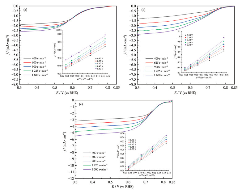
Inset: K-L curves at different potentials.
The incorporation of S/NG with the double perovskite oxide LSNC effectively improved the catalytic performance. SEM observation revealed that the introduction of S/NG mitigated the agglomeration of LSNC particles, promoting uniform dispersion and good contact between the components. XPS analysis indicated an increase in the content of high-oxidation-state oxygen species on the catalyst surface after compositing, which is conducive to the catalytic reaction. Electrochemical measurements confirmed that the composite with LSNC@S/NG-15% possessed the optimal catalytic activity for OER and ORR, exhibiting the highest anodic and cathodic current densities of 356.0 mA·cm-2 (termination potential: 1.97 V) and 300.4 mA·cm-2 (termination potential: 0.37 V), respectively, and the lowest charge transfer resistance. Although the activity of this composite was significantly enhanced compared to pristine LSNC, it remained lower than that of noble metal-based catalysts (e.g., Pt). Therefore, further optimization is required to enhance its potential for practical applications.
LU F F, XIA T, LI Q, WANG J P, HUO L H, ZHAO H. Heterostructured simple perovskite nanorod-decorated double perovskite cathode for solid oxide fuel cells: Highly catalytic activity, stability and CO2-durability for oxygen reduction reaction[J]. Appl. Catal. B‒Environ., 2019, 249: 19-31 doi: 10.1016/j.apcatb.2019.02.056
LU X F, XIA B Y, ZANG S Q, LOU X W. Metal-organic frameworks based electrocatalysts for the oxygen reduction reaction[J]. Angew. Chem.‒Int. Edit., 2020, 59(12): 4634-4650 doi: 10.1002/anie.201910309
BENIYA A, HIGASHI S. Towards dense single-atom catalysts for future automotive applications[J]. Nat. Catal., 2019, 2(7): 590-602 doi: 10.1038/s41929-019-0282-y
KULKARNI A, SIAHROSTAMI S, PATEL A, NORSKOV J K. Understanding catalytic activity trends in the oxygen reduction reaction[J]. Chem. Rev., 2018, 118(5): 2302-2312 doi: 10.1021/acs.chemrev.7b00488
XU F F, WANG J L, ZHANG Y X, WANG W, GUAN T T, WANG N, LI K X. Structure-engineered bifunctional oxygen electrocatalysts with Ni3S2 quantum dot embedded S/N-doped carbon nanosheets for rechargeable Zn-air batteries[J]. Chem. Eng. J., 2021, 432: 134256
YUE Y L, NIU J J, YANG C W, QIN J Q, ZHANG X Y, LIU R P. The OER/ORR activities of copper oxyhydroxide series electrocatalysts[J]. Mol. Catal., 2023, 537: 112942
于文婉, 黄红霞, 王成. La1-xSrxCoO3(x=0, 0.2, 0.4, 0.6, 0.8)钙钛矿型氧化物的催化性能及改性[J]. 无机化学学报, 2018, 34(3): 475-482YU W W, HUANG H X, WANG C. Electrocatalytic properties and modification of La1-xSrxCoO3 (x=0, 0.2, 0.4, 0.6, 0.8) perovskite oxide[J]. Chinese J. Inorg. Chem., 2018, 34(3): 475-482
FU J, CANO Z P, PARK M G, YU A P, FOWLER M, CHEN Z W. Electrically rechargeable zinc-air batteries: Progress, challenges, and perspectives[J]. Adv. Mater., 2017, 29(7): 1604685 doi: 10.1002/adma.201604685
LI Z, WANG W, ZHOU M J, HE B H, REN W Q, CHEN L, XU W Y, HOU Z H, CHEN Y Y. In-situ self-templated preparation of porous core-shell Fe1-xS@N, S co-doped carbon architecture for highly efficient oxygen reduction reaction[J]. J. Energy Chem., 2021, 54: 310-317 doi: 10.1016/j.jechem.2020.06.010
CHOI S R, SO I S, LEE S W, YOO J, SEO Y S. 3D architecture double perovskite NdBa0.5Sr0.5Co1.5Fe0.5O5+δ embedded hollow-net Co3O4 bifunctional electrocatalysts coupled with N-doped CNT and reduced graphene oxide for oxygen electrode reactions[J]. J. Alloy. Compd., 2020, 823: 153782 doi: 10.1016/j.jallcom.2020.153782
HERMANN V, DUTRIAT D, MÜLLER S, COMNINELLIS C. Mechanistic studies of oxygen reduction at La0.6Ca0.4CoO3-activated carbon electrodes in a channel flow cell[J]. Electrochim. Acta, 2000, 46(2/3): 365-372
LIU D, ZHOU P F, BAI H Y, AI H Q, DU X Y, CHEN M P, LIU D, IP W F, LO K H, KWOK C T, CHEN S, WANG S P, XING G C, WANG X S, PAN H. Development of perovskite oxide-based electrocatalysts for oxygen evolution reaction[J]. Small, 2021, 17(43): 2101605 doi: 10.1002/smll.202101605
SNAITH H J. Present status and future prospects of perovskite photovoltaics[J]. Nat. Mater., 2018, 17(5): 372-376 doi: 10.1038/s41563-018-0071-z
SHARMA R, HOODA N, HOODA A, KHASA S. Effect of Fe supplementation on structural and dielectric properties of La2CoMnO6[J]. Mater. Chem. Phys., 2023, 294: 127012 doi: 10.1016/j.matchemphys.2022.127012
SINGH J, KUMAR A, KUMAR A. Facile wet chemical synthesis and electrochemical performance of double perovskite-La2NiMnO6 for energy storage application[J]. Mater. Today-Proc., 2021, 48: 587-589
ASAMOTO M, YAHIRO H. Catalytic property of perovskite-type oxide prepared by thermal decomposition of heteronuclear complex[J]. Catal. Surv. Asia, 2009, 13(4): 221-228 doi: 10.1007/s10563-009-9079-3
TIWARI J N, HARZANDI A M, HA M, SULTAN S, MYUNG C W, PARK H J, KIM D Y, THANGAVEL P, SINGH A N, SHARMA P, CHANDRASEKARAN S S, SALEHNIA F, JANG J W, SHIN H S, LEE Z, KIM K S. High-performance hydrogen evolution by Ru single atoms and nitrided-Ru nanoparticles implanted on N-doped graphitic sheet[J]. Adv. Energy Mater., 2019, 9(26): 1900931 doi: 10.1002/aenm.201900931
XU F F, ZHAO J H, WANG J L, GUAN T T, LI K X. Strong coordination ability of sulfur with cobalt for facilitating scale-up synthesis of Co9S8 encapsulated S, N co-doped carbon as a trifunctional electrocatalyst for oxygen reduction reaction, oxygen and hydrogen evolution reaction[J]. J. Colloid Interface Sci., 2022, 608: 2623-2632 doi: 10.1016/j.jcis.2021.10.182
LI J, WANG S, YUE M F, XING S M, ZHANG Y J, DONG J C, ZHANG H, CHEN Z, LI J F. Graphene-isolated satellite nanostructure-enhanced Raman spectroscopy reveals the critical role of different intermediates on the oxygen reduction reaction[J]. ACS Catal., 2023, 13(2): 849-855 doi: 10.1021/acscatal.2c05802
KHAN K, TAREEN A K, ASLAM M, ZHANG Y P, WANG R H, KHAN S A, KHAN Q U, RAUF M, ZHANG H, OUYANG Z B, GUO Z Y. Facile synthesis of mayenite electride nanoparticles encapsulated in graphitic shells like carbon nano onions: Non-noble-metal electrocatalysts for oxygen reduction reaction (ORR)[J]. Front. Chem., 2020, 7: 934 doi: 10.3389/fchem.2019.00934
HE G J, QIAO M, LI W Y, LU Y, ZHAO T T, ZOU R J, LI B, DARR J A, HU J Q, TITIRICI M M, PARKIN I P. S, N-co-doped graphene-nickel cobalt sulfide aerogel: Improved energy storage and electrocatalytic performance[J]. Adv. Sci., 2017, 4(1): 1600214 doi: 10.1002/advs.201600214
MENG L X, LIU W W, LU Y, LIANG Z Y, HE T, LI J Y, NAN H X, LUO S X, YU J. Lamellar-stacked cobalt-based nanopiles integrated with nitrogen/sulfur co-doped graphene as a bifunctional electrocatalyst for ultralong-term zinc-air batteries[J]. J. Energy Chem., 2023, 81: 633-641 doi: 10.1016/j.jechem.2023.02.035
ZHUANG G L, BAI J Q, TAO X Y, LUO J M, WANG X D, GAO Y F, ZHONG X, LIA X N, WANG J G. Synergistic effect of S, N-co-doped mesoporous carbon materials with high performance for oxygen-reduction reaction and Li-ion batteries[J]. J. Mater. Chem. A, 2015, 3(40): 20244-20253 doi: 10.1039/C5TA05252A
YANG C, JIN H L, CUI C X, LI J, WANG J C, AMINE K, LU J, WANG S. Nitrogen and sulfur co-doped porous carbon sheets for energy storage and pH-universal oxygen reduction reaction[J]. Nano Energy, 2018, 54: 192-199 doi: 10.1016/j.nanoen.2018.10.005
RAN J, WANG T, ZHANG J, LIU Y, XU C, XI S, GAO D. Modulation of electronics of oxide perovskites by sulfur doping for electrocatalysis in rechargeable Zn-air batteries[J]. Chem. Mater., 2020, 32(8): 3439-3446 doi: 10.1021/acs.chemmater.9b05148
WEI C H, LIU J L, HUANG H X, WANG H L, LI C X, WU S L. N-doped graphene/La0.4Sr0.6Co0.8Ni0.2O3 as an efficient electrocatalyst for oxygen electrode[J]. Ionics, 2023, 29(6): 2427-2434 doi: 10.1007/s11581-023-04988-y
LI Q, BAI A Y, XUE Z C, ZHENG Y, SUN H. Nitrogen and sulfur co-doped graphene composite electrode with high electrocatalytic activity for vanadium redox flow battery application[J]. Electrochim. Acta, 2020, 362: 137223 doi: 10.1016/j.electacta.2020.137223
BU Y, NAM G, KIM S, CHOI K, ZHONG Q, LEE J, QIN Y, CHO J, KIM G. Bifunctional electrocatalysts: A tailored bifunctional electrocatalyst: Boosting oxygen reduction/evolution catalysis via electron transfer between N‐doped graphene and perovskite oxides[J]. Small, 2018, 14(28): 1870228
BU Y F, NAM G, KIM S, CHOI K, ZHONG Q, LEE J, QIN Y, CHO J, KIM G. A tailored bifunctional electrocatalyst: Boosting oxygen reduction/evolution catalysis via electron transfer between N-doped graphene and perovskite oxides[J]. Small, 2018, 14(48): 1802767 doi: 10.1002/smll.201802767
SHE S X, ZHU Y, TAHINI H A, HU Z W, WENG S C, WU X H, CHEN Y B, GUAN D Q, SONG Y F, DAI J, SMITH S C, WANG H T, ZHOU W, SHAO Z P. A molecular-level strategy to boost the mass transport of perovskite electrocatalyst for enhanced oxygen evolution[J]. Appl. Phys. Rev., 2021, 8(1): 011407 doi: 10.1063/5.0033912
YOU M S, GUI L Q, MA X, WANG Z B, XU Y, ZHANG J, SUN J, HE B B, ZHAO L. Electronic tuning of SrIrO3 perovskite nanosheets by sulfur incorporation to induce highly efficient and long-lasting oxygen evolution in acidic media[J]. Appl. Catal. B‒Environ. Energy, 2021, 298: 120562 doi: 10.1016/j.apcatb.2021.120562
SUN Y B, DENG R X, CHI C, CHEN X L, PAN Y A, LI J, XIA X H. One-step synthesis of S, N dual-element doped rGO as an efficient electrocatalyst for ORR[J]. J. Electroanal. Chem., 2023, 940: 117489 doi: 10.1016/j.jelechem.2023.117489
RAO S, UPADHYAY J, POLYCHRONOPOULOU K, UMER R, DAS R. Reduced graphene oxide: Effect of reduction on electrical conductivity[J]. J. Compos. Sci., 2018, 2(2): 25 doi: 10.3390/jcs2020025
DAS S K, PEERA S G, KESH A, VARATHAN P, SAHU A K. Fluorine-rich Schiff base ligand derived Fe/N-C-F and Co/N-C-F catalysts for the oxygen reduction reaction: Synthesis, experimental validation, and DFT insights[J]. Sustain. Energy Fuels, 2024, 9(1): 231-246
LIANG Y Y, LI Y G, WANG H L, ZHOU J G, WANG J, REGIER T, DAI H J. Co3O4 nanocrystals on graphene as a synergistic catalyst for oxygen reduction reaction[J]. Nat. Mater., 2011, 10(10): 780-786 doi: 10.1038/nmat3087
ZHONG J W, WU T, WU Q, DU S, CHEN D C, CHEN B, CHANG M L, LUO X H, LIU Y L. N- and S- co-doped graphene sheet-encapsulated Co9S8 nanomaterials as excellent electrocatalysts for the oxygen evolution reaction[J]. J. Power Sources, 2019, 417: 90-98 doi: 10.1016/j.jpowsour.2019.02.024
SIBUL R, KIBENA-POLDSEPP E, MÄEORG U, MERISALU M, KIKAS A, KISAND V, TRESHCHALOV A, SAMMELSELG V, TAMMEVESKI K. Sulphur and nitrogen co-doped graphene-based electrocatalysts for oxygen reduction reaction in alkaline medium[J]. Electrochem. Commun., 2019, 109: 106603 doi: 10.1016/j.elecom.2019.106603
YANG W, FELLINGER T-P, ANTONIETTI M. Efficient metal-free oxygen reduction in alkaline medium on high-surface-area mesoporous nitrogen-doped carbons made from Ionic liquids and nucleobases[J]. J. Am. Chem. Soc., 2011, 133(2): 206-209 doi: 10.1021/ja108039j
LI G, TANG X M, SHENG K, FANG C, ZENG Y D, LU Z M, WANG Y P, ZHOU H, YI Q F. Heteroatom sulfur-modified ZIF-8 derived Zn, N co-doped carbon nanocages as highly efficient ORR catalysts for Zn-air batteries[J]. J. Electrochem. Soc., 2024, 171(6): 066502 doi: 10.1149/1945-7111/ad5380
JU Y, HUANG W, GAO Z, LIU M, HUANG N. Research on ORR and OER performance of Co based catalyst from ZIF-67[J]. Appl. Mater. Today, 2025, 42: 102576 doi: 10.1016/j.apmt.2024.102576
WANG Z H, GONG C, LI G F, CHEN Y J, SUI L N, DONG L F. Plasmonic Ag/N-doped graphene nanoflakes as electrocatalyst for oxygen reduction reaction enhanced by solar energy[J]. ECS J. Solid State Sci. Technol., 2020, 9(8): 1006

Figure 2 SEM images of (a) LSNC, (b) S/NG, (c) LSNC@S/NG-5%, (d) LSNC@S/NG-10%, (e) LSNC@S/NG-15%, and (f) LSNC@S/NG-20%

Figure 4 (a) O1s XPS spectrum of LSNC; (b) XPS survey, (c) O1s, and (d) N1s XPS spectra of LSNC@S/NG-15%

Figure 6 (a) Anodic LSV curves of LSNC and LSNC@S/NG oxygen electrodes and (b) corresponding Tafel plots

Figure 7 (a) Cathodic LSV curves of the LSNC and LSNC@S/NG oxygen electrodes and (b) corresponding Tafel plots

Figure 8 Linear fitting curves of Cdl for the LSNC, S/NG, and LSNC@S/NG oxygen electrodes

Figure 9 Nyquist plots of the LSNC, S/NG, and LSNC@S/NG-15% oxygen electrodes
Inset: equivalent circuit diagram.

Figure 10 ORR polarization curves at different rotational speeds of (a) LSNC, (b) S/NG, and (c) LSNC@S/NG-15%
Inset: K-L curves at different potentials.
Table 1. Elemental composition of S/NG
| Sample | Mass fraction / % | |||
| S | N | C | O | |
| S/NG | 7.68 | 9.29 | 71.84 | 11.19 |
 下载: 导出CSV
Table 2. Specific surface areas of the samples
| Parameter | LSNC | S/NG | LSNC@S/NG-5% | LSNC@S/NG-15% | LSNC@S/NG-20% |
| SBET / (m2·g-1) | 8 | 16 | 9 | 11 | 10 |
下载: 导出CSV
Table 3. Fitting parameters of electrochemical impedance
| Sample | Rs / Ω | Cd / mF | Rct / Ω |
| LSNC | 1.047 | 4.405 | 0.113 |
| S/NG | 1.203 | 0.149 4 | 0.343 |
| LSNC@S/NG-15% | 1.102 | 5.201 | 0.112 |
下载: 导出CSV

 扫一扫看文章


扫一扫关注我们