表 1
样品的制备参数
Table 1.
Preparation parameters for all the samples

随着清洁能源的广泛应用,锂离子电池以其高储能容量、较好的倍率能力和优越的稳定性在储能设备中扮演着越来越重要的角色[1-5]。石墨作为传统的负极材料,在电化学充放电循环中表现出良好的结构稳定性。然而,由于石墨阳极的理论容量相对较低(372 mAh·g-1),使得锂离子电池的能量密度难以进一步提升[6-7],开发高性能负极材料已成为当务之急。硅被认为是最有前途的下一代负极材料之一,它具有远超石墨的高理论容量(约4 200 mAh· g-1)和相对较低的工作电位(约0.4 V(vs Li+/Li)),来源丰富,环境友好[8-12]。然而,硅阳极在锂化/脱锂过程中发生了巨大的体积变化(大于300%),导致结构破坏,不稳定固体电解质界面(SEI)变厚。此外,硅作为半导体,其电子导电性相对较低(小于10-5 S· cm-1)。这些问题导致了硅阳极容量低、循环性能差,阻碍了其在锂离子电池中的实际使用[13-17]。
许多方法已经被用来解决硅阳极的上述问题,如通过适当的结构设计(纳米硅、三维结构等)可以缓冲较大的体积变化[18-20]。然而,这些结构的设计与制作需要较高的成本和复杂的设备,难以实现大规模生产。在硅基体中引入碳涂层是提高其结构稳定性和导电性的常用方法[21-23]。然而,大量引入碳会在一定程度上降低硅阳极的能量密度,在长期充放电循环中保持硅与碳涂层的良好结合仍然是一大问题。另一种提高硅结构稳定性和电子导电性的有效方法是掺杂其它元素[24-27]。Ge等直接蚀刻掺硼硅晶片制备多孔掺硼硅纳米线,其表现出优异的电化学性能和长期循环稳定性[28]。Zhang等通过含磷纳米SiO2的镁热还原制备了均匀交联的磷掺杂多孔硅纳米颗粒,P掺杂对Si阳极的电荷转移有很好的促进作用[29]。近年来,与硅同主族的元素和一些过渡金属元素已被用于Si阳极的掺杂。Cui等利用球磨法将Sn/Ge原子掺杂到Si阳极中,晶格扩张促进了Li+的扩散并减少了Li+的捕获,这有效地提高了硅基阳极的初始库仑效率(90% 以上)[30]。Xu等通过化学置换/蚀刻和低温退火工艺,采用简单且可扩展的策略合成了锡掺杂多孔硅微球(Sn-PSi@Sn)。硅晶格中锡原子的掺杂使硅晶格膨胀,提高了本征电导率[31]。与单相基体材料相比,非活性材料掺杂电极材料表现出更好的稳定性,这是因为非活性基体保护了锂化/脱锂反应过程中结构的完整性[32-33]。Arunakumari等通过低温热处理法制备了掺杂Ni的纳米硅粒子,该纳米硅粒子表现出优异的倍率性能和更快的Li+迁移能力[34]。元素掺杂可以提高硅的电子导电性,从而改善其电化学性能。
本文报道了一种低成本、简单高效的溶液沉积制备双金属(Sn/Ni)掺杂多孔硅微球(pSi@SnNi)的方法。SnO32-/Ni2+离子通过Si溶解产生的电子被还原为Sn/Ni,通过将Sn/Ni沉积、掺杂到pSi中获得pSi@SnNi复合材料。研究发现,含有适量金属掺杂元素的pSi@SnNi复合材料显示了良好的电化学储锂性能,其储锂性能与组成、微观结构之间存在内在关系。
所用化学品均为分析纯。用盐酸蚀刻法制备:将1.0 g SiAl合金粉末(12% Si,约325目,Alfa Aesar公司)均匀分散在1.0 mol·L-1 HCl溶液中,在室温下反应24 h。产品离心收集,用去离子水和乙醇交替洗涤数次。在70 ℃下干燥12 h,得到pSi。
典型pSi@SnNi材料的制备过程如下:用氨水调节含有0.5 mol·L-1 NH4F、0.001 0 mol·L-1 K2SnO3和0.001 0 mol·L-1 NiSO4溶液的pH值至约8.0;在上述体积为100 mL的混合溶液中加入0.1 g pSi,在室温下持续搅拌1 h;离心收集产物,用去离子水和乙醇交替洗涤数次;然后,将样品在70 ℃下干燥10 h,得到最终产品(标记为pSi@SnNi02)。在不同的反应条件下,通过类似的实验过程制备的样品见表 1。
 下载:
导出CSV
下载:
导出CSV
| Sample | Concentration of NH4F/(mol·L-1) | Concentration of K2SnO3/(mol·L-1) | Concentration of NiSO4/(mol·L-1) |
| pSi@SnNi01 | 0.5 | 0.000 5 | 0.000 5 |
| pSi@SnNi02 | 0.5 | 0.001 0 | 0.001 0 |
| pSi@SnNi03 | 0.5 | 0.001 5 | 0.001 5 |
| pSi@Sn | 0.5 | 0.001 0 | — |
| pSi@Ni | 0.5 | — | 0.001 0 |
采用场发射扫描电子显微镜(SEM,HITACHI SU8010,5.0 kV,10 μA)和高分辨率场发射透射电子显微镜(HRTEM, JEM2100F,加速电压200 kV)对样品的微观结构和形貌进行了表征。所有样品的晶体结构信息均通过X射线衍射仪(XRD,Rigaku Ultima Ⅳ,40 kV,30 mA,Cu Kα)以扫描速率为3 (°)· min-1在20°~80°扫描范围内测试得到。采用X射线光电子能谱仪(XPS,ESCALAB 250Xi,15 kV,10 mA,Al Kα)对样品的表面组成和化学状态进行了表征。采用电感耦合等离子体发射光谱仪(ICP-OES,OPTIMA 8000DV)测定了pSi@SnNi复合材料的Si、Sn和Ni含量。
半电池(CR2025型纽扣电池)由工作电极、对电极(锂箔)、聚丙烯隔膜(Celgard 2325)和电解质组成,在氧气含量低于0.143 mg·m-3的氩气填充手套箱中组装。将硅基复合材料、海藻酸钠和乙炔黑用去离子水混成膏状,并均匀涂抹在铜箔上(质量比为7∶ 1.5∶1.5),然后在真空烘箱中60 ℃干燥10 h制成工作电极。硅基复合材料在电极中的负载量约为1.0 mg·cm-2。电解液中含有1 mol·L-1 LiPF6,溶剂为由碳酸甲酯乙酯、碳酸二甲酯、碳酸乙烯(体积比为1∶1∶1)及10% 氟碳酸乙烯(FEC)添加剂组成的混合物。循环伏安(CV)测试使用CHI 660D电化学工作站进行。采用Parstat 2273电化学分析仪在开路电位状态下测试电化学阻抗谱(EIS),振幅为10 mV,频率范围为10 mHz~100 kHz。在不同电流密度下,通过NEWARE仪器在0.01~3 V的电位窗口内进行恒流充放电测试。
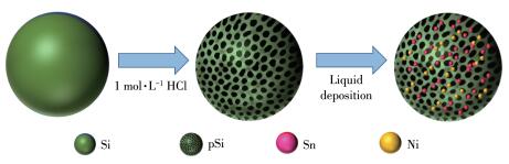
pSi@SnNi复合材料的制备如图 1所示。通过用1 mol·L-1 HCl去除SiAl合金中的铝组分,得到了三维pSi。当向反应溶液中加入pSi时,发生以下反应[35]:
|
|
(1) |
|
|
(2) |
|
|
(3) |
|
|
(4) |
|
|
(5) |
随着上述反应的进行,SnO32-和Ni2+离子被硅阳极溶解产生的电子还原,Sn/Ni沉积并掺杂到pSi中,从而获得pSi@SnNi产物并伴随氢的析出。
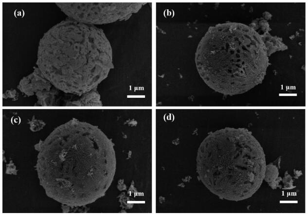
所制备的pSi@SnNi和pSi的SEM图如图 2所示。所有材料均呈直径1~5 μm的球形。pSi为三维多孔球形结构(图 2a),pSi@SnNi01、pSi@SnNi02和pSi@SnNi03复合材料表现出类似的结构,其表面有一些沉积的Sn、Ni颗粒(图 2b~2d)。ICP结果表明,pSi@SnNi02样品中Si、Sn和Ni的质量分数分别为90.4%、8.2%、1.4%。
通过TEM对pSi@SnNi02的微观结构进行了表征。如图 3a、3b所示,pSi@SnNi02为三维多孔微球结构。由HRTEM图(图 3c)可以清楚地看到晶格条纹,晶格间距为0.31 nm,对应为Si (111)晶面。能谱(EDX)元素映射结果表明(图 3d),Si、O、Sn、Ni元素在三维pSi中分布均匀。Sn和Ni元素的引入对于提高复合材料的结构稳定性以及改进电子导电性具有重要意义。复合材料中O元素主要是Si、Sn、Ni氧化的产物。

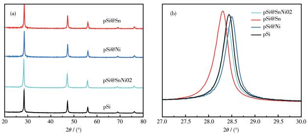
pSi@SnNi02、pSi@Sn、pSi@Ni和pSi的XRD图如图 4a所示。所有制备的材料均显示为晶体硅的特征峰(PDF No.27-1402)。未观察到Sn和Ni的XRD峰,说明Sn/Ni独立相的含量或结晶度较低,或者Sn/ Ni已掺杂到硅晶格中。如图 4b所示,pSi@SnNi02、pSi@Sn和pSi@Ni的Si(111)晶面峰位置相对于pSi的Si(111)晶面峰偏移的方向不同,这是由于Sn的原子半径大于Si,pSi@Sn的Si(111)晶面峰向小角度偏移,即Sn掺杂导致晶格膨胀[31]。相反,原子半径较小的Ni掺杂导致Si晶格收缩,因此pSi@Ni的Si(111)晶面峰向大角度偏移[36]。值得注意的是,pSi@ SnNi02的Si(111)晶面峰的衍射角接近于pSi,而两者均在pSi@Sn和pSi@Ni的Si(111)晶面峰的衍射角之间,这可能意味着Sn和Ni均已被掺杂到Si的晶格中。
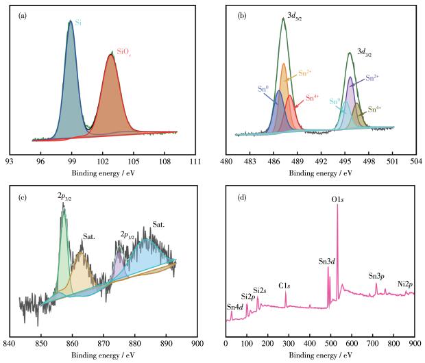
采用XPS对pSi@SnNi02表面的元素组成和价态分布进行了表征。图 5a给出了pSi@SnNi02的Si2p高分辨率XPS谱图。结合能为102.80和98.85 eV处的峰,分别归属于Si—O和Si—Si键[37]。pSi@SnNi02的Sn3d XPS谱图如图 5b所示,原始的2个主峰分别归属于Sn3d5/2和Sn3d3/2轨道;Sn3d5/2轨道可以拟合为488.05、487.35和486.70 eV三个子峰,分别归属为Sn4+、Sn2+和Sn0;Sn3d3/2轨道结合能分别拟合为496.45 eV(Sn4+)、495.75 eV(Sn2+)和495.05 eV(Sn0)[38]。pSi@SnNi02的Ni2p XPS谱图如图 5c所示。Ni2p3/2和对应的卫星峰结合能分别为857.20和862.90 eV,Ni2p1/2和对应的卫星峰结合能分别为874.90和883.90 eV。图 5d中的XPS全谱图显示样品中含有Si、Sn、Ni、O和C元素。O元素的存在归因于Si、Sn、Ni的表面氧化,碳来自于不可避免的污染。
所制备材料的电化学性能如图 6所示。从图 6a可见,在首次CV循环中,位于约0.8 V处的宽还原峰对应于SEI膜的形成[39-41],该峰在随后的循环中消失,表明在pSi@SnNi02表面形成了不可逆的稳定SEI层;在约0.18 V的另一个峰是由硅晶体的非晶态转变和随后的锂离子合金化过程引起的[42-43]。在阳极扫描过程中,以约0.33和约0.52 V为中心的2个主要氧化峰主要是LixSi的两步脱合金过程[44-45]。由于金属掺杂量低,未发现Sn/Ni与锂反应的CV峰。可以看出,随着CV循环的进行,电极的峰值电流逐渐增大,这是电极的逐步电化学活化造成的[46]。pSi@SnNi02电极在0.1 A·g-1下的首次放电/充电曲线如图 6b所示。pSi@SnNi02电极的初始放电和充电比容量分别为2 651.7和3 301.2 mAh·g-1,初始库仑效率为80.33%。在首次循环中,容量损失主要与不可逆SEI膜的形成有关。随后2次循环的电化学比容量分别为2 734.6和2 657.4 mAh·g-1,相关库仑效率迅速增加到95.14%(第2次循环)和94.55%(第3次循环),表明获得了稳定的SEI膜。
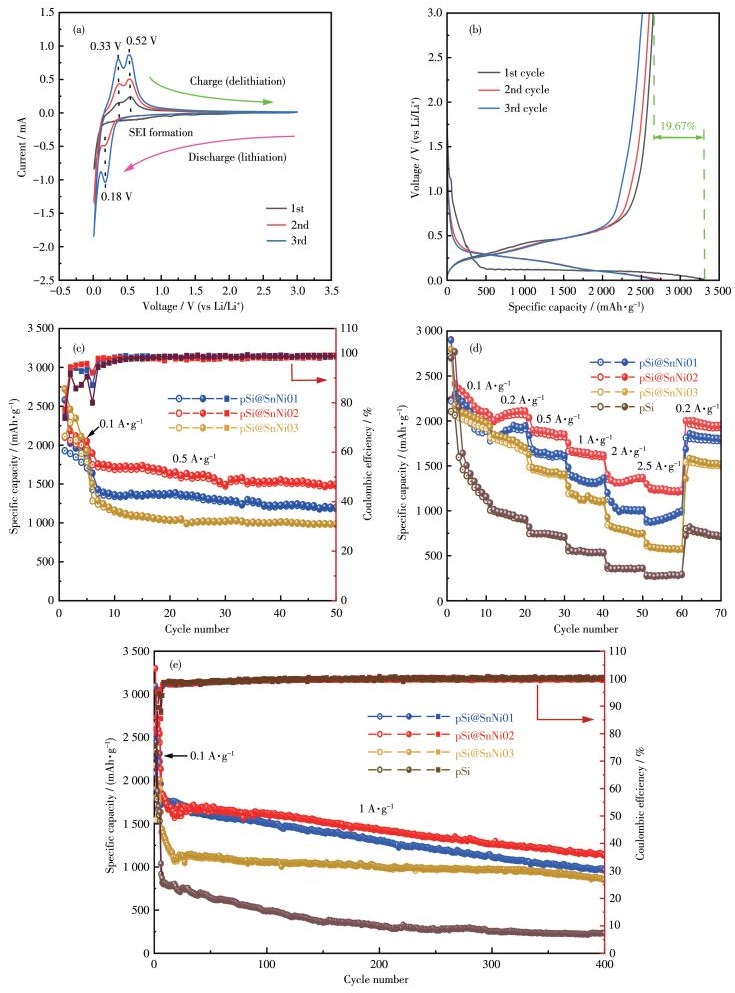
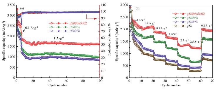
图 6c为在电流密度为0.5 A·g-1时不同电极的循环性能(在0.1 A·g-1的低电流密度下进行5次活化循环)。可以看出,电极在0.5 A·g-1下的电化学比容量高低顺序为pSi@SnNi03 < pSi@SnNi01 < pSi@ SnNi02。pSi@SnNi02显示了最大的电化学比容量,在第50次循环时比容量为1 495.9 mAh·g-1。pSi、pSi@SnNi01、pSi@SnNi02和pSi@SnNi03电极的倍率性能如图 6d所示。在电流密度为0.1、0.2、0.5、1.0、2.0和2.5 A·g-1时,pSi@SnNi02电极的平均比容量分别为2 280.7、2 092.9、1 878.3、1 643.5、1 329.4和1 235.8 mAh·g-1。当电流密度从2.5 A·g-1恢复到0.2 A·g-1时,其比容量为1 976.6 mAh·g-1。在所研究的电极中,pSi@SnNi02电极的倍率性能最佳,pSi电极的倍率性能最差。pSi@SnNi01、pSi@SnNi02和pSi@SnNi03电极的倍率性能顺序与0.5 A·g-1时的循环性能顺序一致。不同电极在较高倍率下的长期电化学循环稳定性如图 6e所示。在0.1 A·g-1的低电流密度下活化5次后,电极在1 A·g-1电流密度下继续循环至400次。pSi表现出最差的循环性能,这是由于Si在Li插入/脱出过程中体积变化大且其电子电导率低[47-48]。pSi@SnNi02表现出最佳的循环性能,在第400次循环时仍能提供1 139.9 mAh·g-1的可逆容量。与pSi@SnNi02相比,pSi@SnNi01由于Sn/Ni含量较低,在第400次循环时比容量为958 mAh·g-1。随着Sn/Ni掺杂量的增加,pSi@SnNi03的初始比容量相对较低,但其循环稳定性明显提高。如图 7所示,pSi@SnNi02显示出比pSi@Sn和pSi@Ni更好的储锂性能。这表明与单金属(Sn或Ni)掺杂相比,双金属(Sn/Ni)掺杂能明显增强pSi的储锂性能。双金属(Sn/Ni)的掺杂提高了复合材料的导电性,缩短了Li+的传输路径,因此pSi@SnNi02显示了优异的电化学储锂性能。
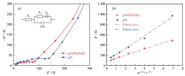
为了理解双金属(Sn/Ni)掺杂对pSi储锂动力学的影响,进行了EIS测试,如图 8a所示。pSi@SnNi02和pSi电极的Nyqusit图由低频区代表锂离子扩散行为的斜线和高频区表示界面电容(CPE)与电荷转移电阻(Rct)的弛豫过程的弥散弧线组成。在图 8a的插图中,Nyqusit图的等效电路包括欧姆电阻(Rs)、CPE、Rct和扩散阻抗(ZW)[49-51]。Warburg阻抗系数(σw)和锂离子扩散系数(D)的计算方法如下[52-53]:
|
|
(6) |
|
|
(7) |
式中T、R、n、A、c、F分别为热力学温度、气体常数、转移电子数、电极面积、Li+的物质的量浓度、法拉第常数[54]。σw可依据式6获得,如图 8b所示。D值可由上述参数值根据式7计算得到,相关结果如表 2所示。与pSi电极相比,pSi@SnNi02电极的Rs、Rct和ZW值较低,而其CPE和D值较大,这意味着其欧姆电阻较小、电化学反应速率较快、扩散阻抗较低、有效电化学面积较大以及锂离子扩散速率较高。EIS结果表明双金属(Sn/Ni)掺杂改善了pSi的电化学储锂动力学,这与pSi@SnNi02增强的储锂性能相符(图 6)。
下载:
导出CSV
| Sample | Rs/Ω | Rct/Ω | CPE/F | ZW/Ω | D/(cm-2·s-1) |
| pSi@SnNi02 | 1.395 | 84.23 | 458.77 | 147.0 | 4.64×10⁻¹⁴ |
| pSi | 2.571 | 146.31 | 42.95 | 211.6 | 1.09×10⁻¹⁴ |
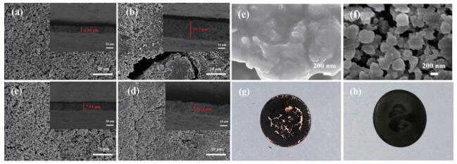
图 9a~9d分别为pSi和pSi@SnNi02电极在1.0 A·g-1电流下循环100次前后的SEM图。循环后电极的高分辨率SEM图和光学照片如图 9e~9h所示。pSi电极在循环后体积膨胀率为223.5%,伴随有较大的表面裂纹,颗粒粉碎、团聚,甚至活性层与集流体部分分离。相比之下,循环后的pSi@SnNi02电极体积膨胀率为43.5%,电极表面变化较小,没有明显的颗粒团聚,活性层与集电流层之间接触较好,这与其良好的电化学循环稳定性是一致的。应该指出的是,pSi@SnNi02电极在电化学循环前后的体积变化率也远小于多种纯硅电极[17]。
与文献报道的锂离子电池硅基负极材料相比[14-20],所构建的pSi@SnNi02具有较好的循环稳定性、优异的倍率性能和较高的比容量,这得益于其奇特的微观结构和特殊组成。三维多孔结构的形成增加了储锂的活性位点,缩短了锂离子的扩散路径,并提供了足够的空间来缓冲硅在放电和充电过程中的急剧体积变化。pSi中双金属(Sn/Ni)的掺杂显著增强了主体Si阳极的电子导电性,并通过改变晶格间距,缩短Li+的传输路径,提高了Li+扩散系数。此外,Sn作为活性元素对于储锂容量有所贡献;非活性金属Ni的掺杂提高了pSi结构稳定性,减小了反应过程中的机械应力所导致的结构变化。从XRD结果也可以看出(图 4),Sn/Ni的掺杂可以导致部分Si晶格的膨胀/收缩,这有利于Li+离子在Si中的扩散及在锂化/脱锂过程中降低Li+在Si晶格中的俘获。
采用液相沉积法制备了双金属(Sn/Ni)掺杂的多孔硅微球(pSi@SnNi)。Si与SnO32-/Ni2+发生化学置换反应,使Sn/Ni沉积/掺杂到pSi中,从而获得pSi@ SnNi复合材料。三维多孔微球结构的形成和双金属(Sn/Ni)掺杂使pSi@SnNi复合材料具有更低的欧姆电阻、更快的电化学储锂动力学和更高的锂离子扩散速率。Sn/Ni掺杂量适中的pSi@SnNi02显示了较高的比容量、较好的电化学循环稳定性和优良的倍率性能。这项工作为未来锂离子电池高性能硅基材料的制备提供了一个简单、低成本的思路。
Tang F, Sun Y G, Dai G X, Yan J L, Lin X J, Qiu J H, Cao A M. Template-free synthesis of Co-based oxides nanotubes as potential anodes for lithium-ion batteries[J]. J. Alloy. Compd., 2022, 895: 162611. doi: 10.1016/j.jallcom.2021.162611
孙林, 谢杰, 刘涛, 黄松超, 张磊, 陈智栋, 姜瑞雨, 金钟. 多孔硅纳米材料的制备及在高能锂电池中的应用[J]. 无机化学学报, 2020,36,(3): 393-405. SUN L, XIE J, LIU T, HUANG S C, ZHANG L, CHEN Z D, JIANG R Y, JIN Z. Preparation of porous silicon nanomaterials and applications in high energy lithium ion batteries[J]. Chinese J. Inorg. Chem., 2020, 36(3): 393-405.
Goodenough J B, Park K S. The Li-ion rechargeable battery: A perspective[J]. J. Am. Chem. Soc., 2013, 135(4): 1167-1176. doi: 10.1021/ja3091438
Obrovac M N, Krause L J. Reversible cycling of crystalline silicon powder[J]. J. Electrochem. Soc., 2007, 154(2): A103-A108. doi: 10.1149/1.2402112
Li L, Deng J, Wang L, Wang C L, Hu Y H. Boron-doped and carboncontrolled porous Si/C anode for high-performance lithium-ion batteries[J]. ACS Appl. Energy Mater., 2021, 4(8): 8488-8495. doi: 10.1021/acsaem.1c01688
Raccichini R, Varzi A, Passerini S, Scrosati B. The role of graphene for electrochemical energy storage[J]. Nat. Mater., 2015, 14(3): 271-279. doi: 10.1038/nmat4170
Yu D D, Chen Q Q, Wan J, Li W, Pan L H, Zhao Z H, Egunb I, Tang Z H, He H Y. Supersized graphitic tube@MoS2 pipelines with abundant ion channels synthesized by selective deposition toward high-performance anodes[J]. ACS Appl. Energy Mater., 2021, 4(7): 6866-6873. doi: 10.1021/acsaem.1c00956
Zhang T, Xu Z X, Guo Y S, Liang C D, Wang J L, Yang J. Building high performance silicon-oxygen and silicon-sulfur battery by in-situ lithiation of fibrous Si/C anode[J]. J. Alloy. Compd., 2019, 806: 335-342. doi: 10.1016/j.jallcom.2019.07.244
Yang D D, Shi J, Shi J H, Yang H B. Simple synthesis of Si/Sn@C-G anodes with enhanced electrochemical properties for Li-ion batteries[J]. Electrochim. Acta, 2018, 259: 1081-1088. doi: 10.1016/j.electacta.2017.10.117
Li X L, Gu M, Hu S Y, Kennard R, Yan P F, Chen X L, Wang C M, Sailor M J, Zhang J G, Liu J. Mesoporous silicon sponge as an antipulverization structure for high-performance lithium-ion battery anodes[J]. Nat. Commun., 2014, 5: 4105. doi: 10.1038/ncomms5105
Liang C, Gao M X, Pan H G, Liu Y F, Yan M. Lithium alloys and metal oxides as high-capacity anode materials for lithium-ion batteries[J]. J. Alloy. Compd., 2013, 575: 246-256. doi: 10.1016/j.jallcom.2013.04.001
Guo J F, Pei S E, He Z S, Huang L A, Lu T Z, Gong J J, Shao H B, Wang J M. Novel porous Si-Cu3Si-Cu microsphere composites with excellent electrochemical lithium storage[J]. Electrochim. Acta, 2020, 348: 136334. doi: 10.1016/j.electacta.2020.136334
龚俊捷, 王建明. 光沉积制备pSi@CoOx高性能锂离子电池负极材料[J]. 无机化学学报, 2021,37,(10): 1773-1781. doi: 10.11862/CJIC.2021.199GONG J J, WANG J M. Photodeposition for preparing porous Si@CoOx composites as high-performance anode material for lithium-ion batteries[J]. Chinese J. Inorg. Chem., 2021, 37(10): 1773-1781. doi: 10.11862/CJIC.2021.199
Jiao M L, Wang Y F, Ye C L, Wang C Y, Zhang W K, Liang C. Highcapacity SiOx (0 ≤ x ≤ 2) as promising anode materials for next-generation lithium-ion batteries[J]. J. Alloy. Compd., 2020, 842: 155774. doi: 10.1016/j.jallcom.2020.155774
Zhang W J. A review of the electrochemical performance of alloy anodes for lithium-ion batteries[J]. J. Power Sources, 2011, 196(1): 13-24. doi: 10.1016/j.jpowsour.2010.07.020
Sun Y M, Liu N A, Cui Y. Promises and challenges of nanomaterials for lithium-based rechargeable batteries[J]. Nat. Energy, 2016, 1: 1-12.
Jin Y, Zhu B, Lu Z D, Liu N, Zhu J. Challenges and recent progress in the development of Si anodes for lithium-ion battery[J]. Adv. Energy Mater., 2017, 7(23): 1700715. doi: 10.1002/aenm.201700715
冯雪娇, 杨军, 努丽燕娜, 王久林. 从SiCl4合成多孔硅/碳复合材料及储锂性能研究[J]. 无机化学学报, 2013,29,(11): 2289-2296. FENG X J, YANG J, NULI Y N, WANG J L. Synthesis and lithium storage performance of porous silicon/carbon composite material from SiCl4[J]. Chinese J. Inorg. Chem., 2013, 29(11): 2289-2296.
Bao Z H, Weatherspoon M R, Shian S, Cai Y, Graham P D, Allan S M, Ahmad G, Dickerson M B, Church B C, Kang Z T, Abernathy Ⅲ H W, Summers C J, Liu M L, Sandhage K H. Chemical reduction of three-dimensional silica micro-assemblies into microporous silicon replicas[J]. Nature, 2007, 446(7132): 172-175. doi: 10.1038/nature05570
Sun W, Kherani N P, Hirschman K D, Gadeken L L, Fauchet P M. A three-dimensional porous silicon p-n diode for betavoltaics and photovoltaics[J]. Adv. Mater., 2005, 17(10): 1230-1233. doi: 10.1002/adma.200401723
Kim M K, Shin W H, Jeong H M. Protective carbon-coated silicon nanoparticles with graphene buffer layers for high performance anodes in lithium-ion batteries[J]. Appl. Surf. Sci., 2019, 467: 926-931.
Nulu A, Nulu V, Sohn K Y. Si/SiOx nanoparticles embedded in a conductive and durable carbon nanoflake matrix as an efficient anode for lithium-ion batteries[J]. ChemElectroChem, 2020, 7(19): 4055-4065. doi: 10.1002/celc.202001130
张林, 王静, 唐艳平, 郭玉忠, 黄瑞安. 有序介孔硅包碳复合结构的制备及其储锂行为[J]. 无机化学学报, 2020,36,(5): 893-900. ZHANG L, WANG J, TANG Y P, GUO Y Z, HUANG R A. Preparation and Li+-storage behaviour of ordered mesoporous Si/C composite structure[J]. Chinese J. Inorg. Chem., 2020, 36(5): 893-900.
Yi R, Zai J T, Dai F, Gordin M L, Wang D H. Improved rate capability of Si-C composite anodes by boron doping for lithium-ion batteries[J]. Electrochem. Commun., 2013, 36: 29-32. doi: 10.1016/j.elecom.2013.09.004
Li P, Hwang J Y, Sun Y K. Nano/microstructured silicon-graphite composite anode for high-energy-density Li-ion battery[J]. ACS Nano, 2019, 13(2): 2624-2633.
Domi Y, Usui H, Shimizu M, Kakimoto Y, Sakaguchi H. Effect of phosphorus-doping on electrochemical performance of silicon negative electrodes in lithium-ion batteries[J]. ACS Appl. Mater. Interfaces, 2016, 8(11): 7125-7132. doi: 10.1021/acsami.6b00386
Lv G X, Zhu B, Li X Q, Chen C L, Li J L, Jin Y, Hu X Z, Zhu J. Simultaneous perforation and doping of Si nanoparticles for lithiumion battery anode[J]. ACS Appl. Mater. Interfaces, 2017, 9(51): 44452-44457. doi: 10.1021/acsami.7b12898
Ge M Y, Rong J P, Fang X, Zhou C W. Porous doped silicon nanowires for lithium ion battery anode with long cycle life[J]. Nano Lett., 2012, 12(5): 2318-2323. doi: 10.1021/nl300206e
Zhang J M, Zhou X Y, Tang J J, Ren Y P, Jiang M, Tang Y G, Wang H Y, Yang J. Phosphoric acid induced homogeneous crosslinked phosphorus doped porous Si nanoparticles with superior lithium storage performance[J]. Appl. Surf. Sci., 2020, 509: 144873. doi: 10.1016/j.apsusc.2019.144873
Zhu B, Liu G L, Lv G X, Mu Y, Zhao Y L, Wang Y X, Li X Q, Yao P C, Deng Y, Cui Y, Zhu J. Minimized lithium trapping by isovalent isomorphism for high initial coulombic efficiency of silicon anodes[J]. Sci. Adv., 2019, 5(11): eaax0651. doi: 10.1126/sciadv.aax0651
Xu Z Y, Hou Y P, Guo J F, Wang J M, Zhou S D. Metallic tin nanoparticle-reinforced tin-doped porous silicon microspheres with superior electrochemical lithium storage properties[J]. ACS Appl. Energy Mater., 2021, 4(12): 14141-14154. doi: 10.1021/acsaem.1c02916
Mahmood N, Zhu J H, Rehman S, Li Q, Hou Y L. Control over largevolume changes of lithium battery anodes via active-inactive metal alloy embedded in porous carbon[J]. Nano Energy, 2015, 15: 755-765. doi: 10.1016/j.nanoen.2015.05.035
Kim Y J, Kim M H, Yang J H, Park J W. Electrochemical properties of aluminum-doped silicon films as anode materials for lithium-ion batteries[J]. J. Korean Phys. Soc., 2006, 49(3): 1196-1201.
Nulu A, Nulu V, Sohn K Y. Influence of transition metal doping on nano silicon anodes for Li-ion energy storage applications[J]. J. Alloy. Compd., 2022, 911: 164976. doi: 10.1016/j.jallcom.2022.164976
Magagnin L, Maboudian R, Carraro C. Gold deposition by galvanic displacement on semiconductor surfaces: Effect of substrate on adhesion[J]. J. Phys. Chem. B, 2002, 106(2): 401-407. doi: 10.1021/jp013396p
Luo C C, Zhou X Y, Ding J, Yang J, Zhou H C, Wang X M, Tang J J. In-situ migration of Ni induced crystallization to boost the initial coulombic efficiency of nano Si anode for lithium ion batteries[J]. Compos. Commun., 2022, 32: 101157. doi: 10.1016/j.coco.2022.101157
Xia M T, Chen B J, Gu F, Zu L H, Xu M Z, Feng Y T, Wang Z J, Zhang H J, Zhang C, Yang J H. Ti3C2Tx MXene nanosheets as a robust and conductive tight on Si anodes significantly enhance electrochemical lithium storage performance[J]. ACS Nano, 2020, 14(4): 5111-5120. doi: 10.1021/acsnano.0c01976
Ye X C, Lin Z H, Liang , S J, Huang X H, Qiu X Y, Qiu Y C, Liu X M, Xie D, Deng H, Xiong X H, Lin Z. Upcycling of electroplating sludge into ultrafine Sn@C nanorods with highly stable lithium storage performance[J]. Nano Lett., 2019, 19(3): 1860-1866. doi: 10.1021/acs.nanolett.8b04944
Nie M, Abraham D P, Chen Y, Bose A, Lucht B L. Silicon solid electrolyte interphase (SEI) of lithium ion battery characterized by microscopy and spectroscopy[J]. J. Phys. Chem. C, 2013, 117(26): 13403-13412. doi: 10.1021/jp404155y
Huang W, Wang H, Boyle D T, Li Y Z, Cui Y. Resolving nanoscopic and mesoscopic heterogeneity of fluorinated species in battery solidelectrolyte interphases by cryogenic electron microscopy[J]. ACS Energy Lett., 2020, 5(4): 1128-1135. doi: 10.1021/acsenergylett.0c00194
Pathak R, Chen K, Gurung A, Reza K M, Bahrami B, Pokharel J, Baniya A, He W, Wu F, Zhou Y, Xu K, Qiao Q Q. Fluorinated hybrid solid-electrolyte-interphase for dendrite-free lithium deposition[J]. Nat. Commun., 2020, 11(1): 93. doi: 10.1038/s41467-019-13774-2
Saint J, Morcrette M, Larcher D, Laffont L, Beattie S, Pérès J P, Talaga D, Couzi M, Tarascon J M. Towards a fundamental understanding of the improved electrochemical performance of silicon-carbon composites[J]. Adv. Funct. Mater., 2007, 17(11): 1765-1774. doi: 10.1002/adfm.200600937
Wang H X, Song H C, Lin Z X, Jiang X F, Zhang X W, Yu L W, Xu J, Pan L J, Wang J Z, Zheng M B, Shi Y, Chen K J. Highly crosslinked Cu/a-Si core-shell nanowires for ultra-long cycle life and high rate lithium batteries[J]. Nanoscale, 2016, 8(5): 2613-2619. doi: 10.1039/C5NR06985H
Wu L L, Zhou H C, Yang J, Zhou X Y, Ren Y P, Nie Y, Chen S. Carbon coated mesoporous Si anode prepared by a partial magnesiothermic reduction for lithium-ion batteries[J]. J. Alloy. Compd., 2017, 716: 204-209. doi: 10.1016/j.jallcom.2017.05.057
Wu L L, Yang J, Zhou X Y, Zhang M F, Ren Y P, Nie Y. Silicon nanoparticles embedded in a porous carbon matrix as a high-performance anode for lithium-ion batteries[J]. J. Mater. Chem. A, 2016, 4(29): 11381-11387. doi: 10.1039/C6TA04398D
Kravchyk K, Protesescu L, Bodnarchuk M I, Krumeich F, Yarema M, Walter M, Guntlin C, Kovalenko M V. Monodisperse and inorganically capped Sn and Sn/SnO2 nanocrystals for high-performance Li-ion battery anodes[J]. J. Am. Chem. Soc., 2013, 135(11): 4199-4202. doi: 10.1021/ja312604r
Wang K, Pei S E, He Z S, Huang L A, Zhu S S, Guo J F, Shao H B, Wang J M. Synthesis of a novel porous silicon microsphere@carbon core-shell composite via in situ MOF coating for lithium ion battery anodes[J]. Chem. Eng. J., 2019, 356: 272-281. doi: 10.1016/j.cej.2018.09.027
He Z S, Huang L A, Guo J F, Pei S E, Shao H B, Wang J M. Novel hierarchically branched CoC2O4@CoO/Co composite arrays with superior lithium storage performance[J]. Energy Storage Mater., 2020, 24: 362-372. doi: 10.1016/j.ensm.2019.07.037
Rashed M Z, Kopechek J A, Priddy M C, Hamorsky K T, Palmer K E, Mittal N, Valdez J, Flynn J, Williams S J. Rapid detection of SARS-CoV-2 antibodies using electrochemical impedance-based detector[J]. Biosens. Bioelectron., 2021, 171: 112709. doi: 10.1016/j.bios.2020.112709
Wang B, Ryu J, Choi S, Zhang X H, Pribat D, Li X L, Zhi L J, Park S, Ruoff R S. Ultrafast-charging silicon-based coral-like network anodes for lithium-ion batteries with high energy and power densities[J]. ACS Nano, 2019, 13(2): 2307-2315.
Tian Y, An Y L, Feng J K. Flexible and freestanding silicon/MXene composite papers for high-performance lithium-ion batteries[J]. ACS Appl. Mater. Interfaces, 2019, 11(10): 10004-10011. doi: 10.1021/acsami.8b21893
Huang L A, He Z S, Guo J F, Pei S E, Shao H B, Wang J M. Selfassembled three-dimensional graphene aerogel with an interconnected porous structure for lithium-ion batteries[J]. ChemElectroChem, 2019, 6(10): 2698-2706. doi: 10.1002/celc.201900445
Lu Z D, Liu N, Lee H W, Zhao J, Li W Y, Li Y Z, Cui Y. Nonfilling carbon coating of porous silicon micrometer-sized particles for high-performance lithium battery anodes[J]. ACS Nano, 2015, 9(3): 2540-2547. doi: 10.1021/nn505410q
Lu J, Chen Z W, Pan F, Cui Y, Amine K. High-performance anode materials for rechargeable lithium-ion Batteries[J]. Electrochem. Energy Rev., 2018, 1(1): 35-53. doi: 10.1007/s41918-018-0001-4

图 1 以SiAl合金为前驱体制备pSi@SnNi复合材料的示意图
Figure 1 Schematic illustration for fabrication of pSi@SnNi composites using SiAl alloy as a precursor

图 2 pSi (a)、pSi@SnNi01 (b)、pSi@SnNi02 (c)和pSi@SnNi03 (d)的SEM图
Figure 2 SEM images of pSi (a), pSi@SnNi01 (b), pSi@SnNi02 (c), and pSi@SnNi03 (d)

图 3 pSi@SnNi02的TEM图(a、b)、HRTEM图(c)和EDX元素映射图(d)
Figure 3 TEM images (a, b), HRTEM image (c), and EDX elemental mappings (d) of pSi@SnNi02

图 4 pSi@Sn、pSi@Ni、pSi@SnNi02和pSi (a)及相应Si(111)晶面(b)的XRD图
Figure 4 XRD patterns of pSi@Sn, pSi@Ni, pSi@SnNi02, and pSi (a) and corresponding Si (111) plane (b)

图 5 pSi@SnNi02的高分辨率Si2p (a)、Sn3d (b)、Ni2p (c) XPS谱图和全谱图(d)
Figure 5 High-resolution Si2p (a), Sn3d (b), Ni2p (c) XPS spectra, and full XPS spectrum (d) of pSi@SnNi02

图 6 (a) 0.1 mV·s-1下pSi@SnNi02的CV曲线; (b) pSi@SnNi02在0.1 A·g-1下的恒流充放电曲线; (c) pSi@SnNi01、pSi@SnNi02和pSi@SnNi03在0.5 A·g-1下的循环性能; pSi@SnNi01、pSi@SnNi02、pSi@SnNi03和pSi的(d) 倍率性能和(e) 长循环性能
Figure 6 (a) CV curves of pSi@SnNi02 at 0.1 mV·s-1; (b) Galvanostatic charge-discharge curves of pSi@SnNi02 at 0.1 A·g-1; (c) Cycling performance of pSi@SnNi01, pSi@SnNi02, and pSi@SnNi03 at 0.5 A·g-1; (d) Rate capabilities and (e) long-term cycling performance of pSi@SnNi01, pSi@SnNi02, pSi@SnNi03, and pSi

图 7 (a) pSi@SnNi02、pSi@Sn和pSi@Ni在1.0 A·g-1下的循环性能; (b) pSi@SnNi02、pSi@Sn、pSi@Ni和pSi的倍率性能
Figure 7 (a) Cyclic performance of pSi@SnNi02, pSi@Sn, and pSi@Ni at 1 A·g-1; (b) Rate capabilities of pSi@SnNi02, pSi@Sn, pSi@Ni, and pSi

图 8 (a) pSi@SnNi02和pSi电极在开路状态下以1 A·g-1循环500次后的Nyquist图(插图: 相应的等效电路图); (b) 由Nyquist图推导出的低频区实阻抗(Z′)与角频率(ω-0.5)的关系
Figure 8 (a) Nyquist plots of pSi@SnNi02 and pSi electrodes in an open circuit state after 500 cycles at 1 A·g-1 (Inset: corresponding equivalent circuit); (b) Relationship of real impedance (Z′) and angular frequency (ω-0.5) in the low-frequency region derived from the Nyquist plots

图 9 pSi (a、b)和pSi@SnNi02 (c、d)电极在1 A·g-1下100次循环前(a、c)和后(b、d)的SEM图(插图: 电极的截面SEM图); 1 A·g-1下100次循环后pSi (e)和pSi@SnNi02 (f)电极的SEM图; 1 A·g-1下100次循环后pSi (g)和pSi@SnNi02 (h) 电极的光学照片
Figure 9 SEM images of pSi (a, b) and pSi@SnNi02 (c, d) electrodes before (a, c) and after (b, d) 100 cycles at 1 A·g-1 (Inset: sectional SEM images of the electrodes); SEM images of pSi (e) and pSi@SnNi02 (f) electrodes after 100 cycles at 1 A·g-1; Optical photographs of pSi (g) and pSi@SnNi02 (h) electrodes after 100 cycles at 1 A·g-1
表 1 样品的制备参数
Table 1. Preparation parameters for all the samples
| Sample | Concentration of NH4F/(mol·L-1) | Concentration of K2SnO3/(mol·L-1) | Concentration of NiSO4/(mol·L-1) |
| pSi@SnNi01 | 0.5 | 0.000 5 | 0.000 5 |
| pSi@SnNi02 | 0.5 | 0.001 0 | 0.001 0 |
| pSi@SnNi03 | 0.5 | 0.001 5 | 0.001 5 |
| pSi@Sn | 0.5 | 0.001 0 | — |
| pSi@Ni | 0.5 | — | 0.001 0 |
 下载: 导出CSV
表 2 由Nyquist图拟合得到的阻抗参数
Table 2. Impedance parameters obtained by the fitting of the Nyquist plots
| Sample | Rs/Ω | Rct/Ω | CPE/F | ZW/Ω | D/(cm-2·s-1) |
| pSi@SnNi02 | 1.395 | 84.23 | 458.77 | 147.0 | 4.64×10⁻¹⁴ |
| pSi | 2.571 | 146.31 | 42.95 | 211.6 | 1.09×10⁻¹⁴ |
下载: 导出CSV

 扫一扫看文章

扫一扫关注我们
 下载:
下载: