Received Date:
24 October 2021 Revised Date:
31 March 2022 Available Online:
10 May 2022
Abstract:
Pt nanowires (Pt NWs) have been demonstrated to have a higher specific activity of oxygen reduction reaction (ORR) than that of commercial Pt/C due to their unique structural characteristics. In this work, a cathode with a uniform distribution of Pt NWs was obtained by introducing preformed Pt nanoparticles (NPs) into the carbon matrix to induce Pt NW growth. The structure and performance of the as-prepared cathode were investigated by altering Pt NP loadings (0-0.015 mg·cm-2) and Pt NP sources (Pt/C with different Pt contents). The cathode surface was characterized by scanning electron microscopy (SEM), and the morphology and crystal structure of Pt NW were analyzed by transmission electron microscopy (TEM) and X -ray diffraction (XRD). Polarization and cyclic voltamme-try curves were obtained in single cells. The best single-cell performance, as well as the largest electrochemical surface area (ECSA) value was achieved by the cathode with preformed Pt NP loading of 0.005 mg·cm-2 originating from 40% Pt/C. Finally, a possible mechanism for the influence of preformed Pt NPs in the Pt NW distribution was proposed.
Of all the advanced electrochemical energy con-version technologies, the proton exchange membrane fuel cells (PEMFCs) represent a highly attractive one, particularly promising in portable equipment and trans-portation application[1-2]. The catalyst layer (CL), a con-tinuous network of ionomer and electrocatalyst, is a critical part of the membrane electrode assembly (MEA) in PEMFC. At the current technology status, the significant reliance on expensive Pt -based electrocata-lysts contained in the CLs remains an obstacle to the widespread commercialization of PEMFC[3-4]. This is why optimization of CL structure is essential for increasing Pt utilization efficiency (thus decreasing the amount of Pt needed) as well as improving fuel cell performance, particularly the cathode catalyst layer where the oxygen reduction reaction (ORR) happens[5-6].
Although Pt/C (platinum nanoparticles (Pt NPs) supported on high surface area carbon) provides an excellent catalytic activity towards the inherently sluggish ORR, the challenges of low stability and dura-bility of zero-dimensional (0D) structural material persist in the cathodic environment[7]. Single-crystal one-dimensional (1D) Pt nanostructures, such as nano-rod, nanowire (NW), and nanotube allow for the prefer-ential exposure of low energy crystal facets and lattice planes with fewer lattice boundaries. This helps to reduce the surface energy of the whole system and be highly active for catalysis. The smooth single-crystalline planes can also minimize the number of undesirable low-coordination defect sites which are less catalytically active and vulnerable to oxidation and decomposi-tion[8-12]. The majority of 1D Pt nanostructures are obtained using either hard templates or soft templates. Zhang et al. [13] provided a report on the facile fabrica-tion of ordered nanoporous Pt NWs with controlled large mesopores by chemical reduction deposition from dual templates; the porous anodic aluminum oxide (AAO) membranes were used with the silica nano-spheres self-assembled in the channels. Wang et al.[14] described the preparation of highly ordered hierarchi-cal Pt and Pt-Ni NW arrays using CdS hierarchical NW arrays (HNWAs) as sacrificial templates. Yamauchi et al.[15] prepared Pt nanorods by using a polycarbonate mesoporous membrane as a template. While the tem-plate approach is an efficient method for constraining the growth of metallic objects, it is always accompanied by tedious pre-synthesis and post-synthesis steps, thereby limiting the broad application of this approach. Sun et al. proposed a template-free synthesis of Pt NWs at room temperature using formic acid to reduce hexachloroplatinic acid. Pt NWs were either unsupport-ed or supported on different media like carbon paper, carbon black powder, and carbon nanotube[16-19]. Meng et al.
[20] investigated a template-free synthesis of Pt NWs via the chemical reduction of various Pt salt pre-cursors with formic acid. Hexachloroplatinic acid has been the most used Pt salt precursor for template-free chemical reduction of Pt with formic acid.
While high-performance catalyst is crucial to obtaining a high-performance MEA, the proper micro-structure of CLs is also of great importance. The commercial CL, usually prepared by random mixing of Pt/C catalysts and ionomer, is a porous medium with randomly distributed hydrophobic and hydrophilic sites. In such CL, a significant amount of Pt is wasted as it cannot take part in the electrochemical reaction which occurs at the triple-phase-boundary (TPB) zones[21]. 3D-ordered electrodes were developed to reduce the transport limitation, by introducing either an ordered proton conductor or an ordered electron con-ductor. As a typical example of building ordered proton conductor, the 3M (Minnesota Mining and Manufactur-ing Corporation) nanostructured thin film (NSTF) elec-trode is composed of arrays of oriented short crystalline organic-pigment whiskers, fully covered by a thin Pt or Pt-based alloy catalyst layer[22]. To establish electrodes with ordered electron conductors, vertically aligned carbon nanotubes (VACNTs) are introduced to support Pt NPs[23]. Apart from the construction of the ordered support structure, arrays of 1D catalyst nanostructures, i. e., Pt and Pt alloy NWs and nanotubes, were also introduced to fabricate 3D-ordered CLs. By a facile in.-situ. growing approach using a formic acid-reducing method, Du et al.[24] developed gas diffusion electrodes (GDEs) with Pt NW arrays in.-situ. grown on GDLs.
Our research differs from the aforementioned approaches because the Pt NW arrays were grown on PEM[25] and decal substrate[26] by introducing a carbon matrix layer. This technique enabled the nucleation sites to overcome the inert surface challenge experi-enced by the GDE approaches. In this work, to prevent Pt NW aggregation in the pure carbon matrix, which is caused by relatively high formic concentration in the deposition process, seed-mediated growth of nanostruc-tures was adopted; it involves the use of small NP seeds as nucleation centers to grow NPs to the desired size[27]. The efficacy of this method to control nanostruc-ture growth is well-proven and it is widely used in wet chemical deposition-related processes[28-32]. The effects of the amount of pre-existing Pt NPs on the Pt NW elec-trode morphology and cell performance were explored. Besides, three types of Pt/C (20%, 40%, 60%) as Pt NP sources were used to investigate the effects of seed dis-tribution on the distribution of Pt NWs. The morpholo-gy and Pt distribution of the as-prepared electrodes were analyzed by scanning electron microscopy (SEM) and transmission electron microscopy (TEM) measure-ments. These electrodes were tested as cathodes in a single PEMFC. Finally, the mechanism of preformed Pt NPs on Pt NW distribution of cathode is proposed.
1.
Experimental
1.1
Material
All chemicals and materials were used as received without any further purification. Hexachloroplatinic acid (H2PtCl6·6H2O, 99.95%, Aladdin Industrial Corporation) was used as the precursor of Pt. Formic acid (HCOOH, 88%) and isopropanol (C3H 8O, 99.7%) were purchased from Sinopharm Chemical Reagent Co., Ltd. and used as reducing agents and solvents, respectively. Carbon powder (Vulcan XC-72R, Shanghai Cabot Chemical Co., Ltd.) and 20%, 40%, and 60% Pt/ C (Johnson Matthey) were used to prepare the mixed matrix for Pt NWs growth. 40% Pt/C was used as the anode catalyst. Nafion® ionomer solution (10%, DuPont) and Nafion® 211 membranes (27.5 µm, DuPont) were purchased from Ion Power, Inc. Gas diffusion layers (GDLs, GDS3250, 238 µm thickness@5.0 N·cm-2) were purchased from Fuel Cell Store company. Ultra-premium grade glass fabric coated polytetrafluoroethyl-ene (PTFE) purchased from CS Hyde company was used as the sealing gasket. Ultrapure water (> 18.2 MΩ· cm) used in this work was obtained from the Instrumen-tal Analysis Center of Shanghai Jiao Tong University (IAC-SJTU).
1.2
Preparation of Pt NW cathode and MEA
Similar to our previous work[26], all the cathodes were fabricated by a decal transfer method. The differ-ence was that a trace amount of Pt/C acting as seeds was added into the matrix to induce the uniform growth of Pt NWs. To establish a matrix layer, carbon black, Pt/C, Nafion solution (the mass ratio of Pt/C+C and Nafion was 9∶1) and isopropanol were mixed, followed by a 10 min ultrasonic dispersion step to make a uniform slurry. The resulting solution was then sprayed onto a PTFE transfer substrate of 10 cm2 under an infrared lamp. During the research, the Pt NP contents and local Pt NP densities changed independently. At first, Pt NPs were all originated from 40% Pt/C and the Pt NP content was adjusted by varying the 40% Pt/C additive amount from 0 to 0.015 mg·cm-2. Then, to study the effect of local Pt NP densities, the Pt NP con-tent was fixed at 0.005 mg·cm-2 and the Pt NP sources were 20%, 40%, and 60% Pt/C, respectively.
The PTFE coated with matrix was then fixed in the bottom of a petri dish and infiltrated with ethanol aqueous solution. After 1 min, the solution was poured away and a certain amount of H 2PtCl6·6H2O, HCOOH, and ultra-pure water was added to grow Pt NWs of the desired loading. To grow Pt NWs of 0.2 mg·cm-2, 5.3 mg of H2PtCl6·6H2O (2 mg Pt), 20 mL of ultra-pure water, and 0.533 mL of formic acid were added. The concentration of formic acid in the solution was 0.590 mol·L-1. This concentration was relatively high and could lead to an obvious agglomeration of Pt NWs when there were no preformed Pt NPs in the carbon matrix[33]. The loading of Pt NWs on the matrix was con-trolled by monitoring the Pt precursor weight against the supporting PTFE area for all samples. The mixed solution was kept stationary at 20 ℃ for 48 h. After that, the PTFE samples were taken out and rinsed repeatedly 5-6 times, and then dried. Finally, to expand the triple -phase-bound zones of the electrodes, 0.1 mg·cm-2 (dry basis) of Nafion was mixed with 2 mL isopropanol and stirred by ultrasound for 5 min and subsequently sprayed onto the surface of each cathode, respectively. The Pt NW catalyst layer coated on PTFE was placed to face a Nafion 211 membrane and trans-ferred onto it by hot pressing at 145 ℃ for 3 min under 0.4 MPa pressure. When the decal substrate was peeled off after cooling down, the Pt NW catalyst layer was already coated on the membrane as a cathode.
The anode of each MEA was fabricated as follows. 40% Pt/C, Nafion solution, and isopropanol were mixed and sonicated for 15 min to form a uniform ink. The ink was then sprayed onto a GDL to form a gas diffu-sion electrode (GDE). The Pt loading and the Nafion content at the anode were 0.30 mg·cm-2 and 30%, respectively.
With a GDL put upon the cathode side of the membrane and a GDE upon the opposite side of the membrane, all the components of MEA were hot-pressed at 130 ℃ for 2 min under 0.2 MPa to obtain an MEA.
1.3
Single-cell test
The active area of all the MEAs was 10 cm2; Two graphite flow field plates consisting of two-channel ser-pentine configuration were used in the single-cell set-up. The single-cell activation process and polarization curve test were performed on a fuel cell test platform (MiniTest 3000, Toyo) integrated with an electronic load (PLZ164WA, KIKUSUI). The break-in of MEA was carried out following a two-step program: (a) 10 min@open-circuit voltage (OCV) → 20 min@0.60 V → 20 min@0.70 V → 20 min@0.80 V → 20 min@ 0.85 V → 20 min@0.90 V → 10 min@OCV, repeated 2 times; (b) 10 min@0.2 V → 30 s@OCV, repeated 8 times. High purity hydrogen (99.999%) and air from the oil-less compressor were humidified at 70 ℃ and supplied at a fixed flow rate of 220 and 500 mL·min-1, respectively. The cell temperature was kept at 75 ℃.
The polarization curve was obtained by measuring the current density at various applied voltages (0.90, 0.85, 0.80, 0.75, 0.70, 0.65, 0.60, 0.55, 0.50, 0.45, 0.40 V) with a cell temperature of 70 ℃. Each voltage was held for 5 min, collecting 30 min-1, and the last 60 points were averaged for curve plotting. The flow rates of anode and cathode feeds were kept the same as the activation process. The hydrogen and air were fed at a 65 ℃ humidification temperature without backpressure.
Cyclic voltammetry (CV) was used to estimate the electrochemical surface area (ECSA) of the Pt NW cathode. The CV curve was recorded by Solartron EnergyLab XM connected to a cell where the cathode and the anode were fed with vapor-saturated N2 and H2 at a flow rate of 65 and 300 mL·min-1, respectively. The anode served as both the reversible reference elec-trode and the counter electrode. The cell temperature was kept at 35 ℃ and the potential cycle of the CV tests was from 0.05 to 1.0 V (vs RHE) with a sweep rate of 25 mV·s-1.
1.4
Physical characterization
The top-view images of the Pt NW cathode were observed by SEM. To make SEM samples, the MEAs were disassembled and the cathode coated membranes were cut into small pieces and adhered onto the sample stage with conductive carbon tape. A Leo Supra 55 SEM with an accelerating voltage of 5 kV was used. The high-resolution images of the Pt NWs were taken with a field emission transmission electron microscope (TEM) (JEM-2100F, JEOL) operating at an accelerat-ing voltage of 200 kV. The XRD patterns of the carbon-supported Pt NW powders were carried out on a poly-functional X-ray diffractometer (D8 Advance Davinci, Bruker) instrument using Cu Kα. radiation (λ= 0.154 056 nm) generated at 40 kV/30 mA between 10° and 80° (2θ). To prepare samples for TEM and XRD measurement, the MEAs were disassembled after the fuel cell test and some powders were scraped from the surface of the cathode catalyst layer.
2.
Result and discussion
2.1
Effects of Pt NP contents
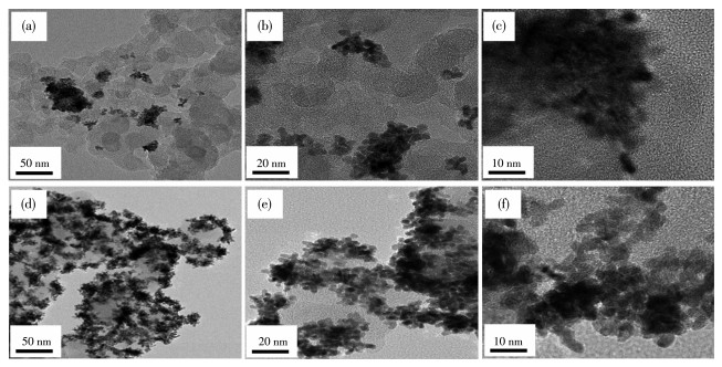
The morphology of Pt NWs supported on carbon was examined by TEM analysis. For comparison, the TEM images of powders scraped from Pt NW cathode with 0 and 0.005 mg·cm-2 Pt NPs were taken up. As shown in Fig. 1a and 1b, Pt NWs grown on the matrix without Pt NPs were distributed unevenly and aggregat-ed seriously, which is consistent with our previous study[33]. This phenomenon occurs because the matrix layer consists of only the inert carbon spheres coated with Nafion ionomer; only limited rough sites of carbon sphere surface and joint positions of carbon spheres or carbon aggregates can serve as the main heterogeneous nucleation sites in the reduction. Fig. 1d reveals that the pre-existing Pt NPs improved the growing uniformi-ty of the Pt NWs relative to the pure carbon matrix case in Fig. 1a. This is because the Pt NPs mixed into the matrix provide favorable sites for Pt nucleation and induce the anisotropic growth of the Pt NWs in the same way as Au and Pd seeds[34-35]. Besides, these Pt NPs may also play the role of catalyst for Pt reduction reaction. Du et al.[36] posited that Pd NPs could act as catalytic sites for the anisotropic Pt growth, and once the growth was touched off, the Pt NWs continually grew in the (111) direction until the supply of Pt atoms was exhausted. As shown in Fig. 1a and 1d, Pt NWs are longer and evenly tend unordered when preformed Pt NPs were added to the matrix. This confirms that the Pt NPs function as growing sites for Pt NWs.
Figure 1
Figure 1.
TEM images with different magnifications of Pt NWs grown on different matrixes, with Pt NPs loading of (a-c) 0 mg·cm-2 and (d-f) 0.005 mg·cm-2, respectively
Pt NW loading and carbon loading of all samples were 0.2 and 0.1 mg·cm-2, respectively
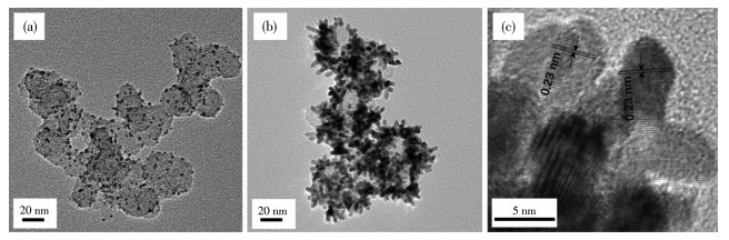
To analyze the morphology change of Pt nano-structure before and after reduction, the morphology of matrix with Pt NPs loading of 0.005 mg·cm-2 and Pt NWs grown on it were examined by TEM, as shown in Fig. 2. The Pt NPs possess a diameter of 2-3 nm and distribute evenly on the carbon spheres, which are then working as seeds for the following growth to Pt NWs. As shown in Fig. 2b, the diameter of as-obtained Pt NWs was ca.. 4 nm, the length was ca.. 8-16 nm and the aspect ratio was ca.. 2-4. An HRTEM image shown in Fig. 2c displays typical Pt NWs and we can see that all the Pt NWs grew along the (111) direction. The crystal-lographic alignment of the NWs reveals that the entire NW is one single crystal with the lattice spacing between (111) planes of 0.23 nm, which is in agree-ment with the value of bulk crystal.
Figure 2
Figure 2.
TEM images of (a) matrix with Pt NP loading of 0.005 mg·cm-2 and (b) Pt NWs grown on it;
(c) HRTEM image of typical Pt NWs
Pt NW loading and carbon loading were 0.2 and 0.1 mg·cm-2, respectively and Pt NPs were originated from 40% Pt/C
To illustrate the influence of Pt NP contents on Pt NW crystallinity, the XRD patterns of the Pt NW cath-odes with the Pt NP loadings of 0, 0.005, and 0.015 mg·cm-2 were measured. As shown in Fig. 3, all XRD patterns of the samples exhibited similar characteris-tics peaks at 2θ. of 39.5°, 46.9°, and 67.3°, which corre-spond to the (111), (200), and (220) facets. The sam-ples with the Pt NP loadings of 0 and 0.005 mg·cm-2 had sharp and intense peaks of the (111) facet, which means perfect crystallinity and dominant (111) facets. However, in the case of the Pt NP loading of 0.015 mg· cm-2, many more growing sites were introduced, which caused less crystallinity or amorphous structure of Pt NWs. This happened because the Pt NP loading of more than 0.005 mg·cm-2 exceeds an appropriate nucleation site value for depositing 0.2 mg·cm-2 Pt and there are not enough Pt atoms for all the Pt crystal particles to achieve high crystallinity. The correspond-ing single-cell performance of each cathode proves that the crystallinity of nanostructures is one of the main factors that influence their catalytic activity and it is consistent with the findings of other publications[37-39].
Figure 3
Figure 3.
XRD patterns of the Pt NW cathodes with Pt NP loadings of 0, 0.005, and 0.015 mg·cm-2, respectively
Pt NW loading and carbon loading of all samples were 0.2 and 0.1 mg·cm-2, respectively
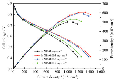
The polarization curves and main performance data of various homemade Pt NW cathodes with differ-ent Pt NP loadings are shown in Fig. 4 and Table 1, respectively. Fig. 4 shows that the single-cell perfor-mance is affected significantly by the Pt NP loading; it also reveals that the optimal cell performance was obtained at 0.005 mg·cm-2, with the current density of 0. 86 A·cm-2 at 0.6 V, which was 21% higher than that of cathode without Pt NP. Meanwhile, a comparative analysis of the cathodes with Pt NP loading of 0 and 0.005 mg·cm-2 showed an increase in the mass-specific current density from 3.5 to 4.2 mA·µgPt-1. This indicates that the inducement of Pt NPs in the matrix could effectively improve the utilization of Pt. And it could be mainly attributed to the better growing unifor-mity of Pt NWs with the presence of preformed Pt NPs as shown in Fig. 1. By contrast, further increasing the Pt NP loading from 0.005 to 0.015 mg·cm-2 causes a decrease in cell performance. This could be mainly attributed to two reasons. Firstly, Pt NPs needed for Pt NW growth depend on the desired Pt NW loading; when the desired Pt NW loading remains unchanged, excessive Pt NPs serving as nucleation sites could lead to different Pt nanostructure instead of clear Pt NW (i.e. lower crystallinity), resulting in a lower ORR activ-ity. Secondly, when the Pt NP source is fixed, the car-bon loading in the matrix increases with the Pt NP load-ing and leads to a higher cathode thickness, as shown in Table 1. A cathode with 0.015 mg·cm-2 Pt NP load-ing has a 1.14-fold carbon loading than that with 0.005 mg·cm-2 Pt NP, which roughly means a 1.14-fold cathodic thickness. A thicker cathode catalyst layer is considered to cause a higher mass transfer resistance, thus weakening its single-cell performance[40-41].
Figure 4
Figure 4.
Polarization curves of Pt NW cathodes with various Pt NP loadings from 0 to 0.015 mg·cm-2
Pt NW loading and carbon loading of all cathodes were 0.2 and 0.1 mg·cm-2, respectively and Pt NPs were originated from 40% Pt/C
Mass specific current density@ 0.6 V/(mA • μgPt-1)
C
0
0.100
0.71
3.50
40% Pt/C+C
0.005
0.108
0.86
4.20
40% Pt/C+C
0.010
0.115
0.83
4.00
40% Pt/C+C
0.015
0.123
0.76
3.55
2.2
Effects of Pt NP sources
To investigate the effects of Pt NP sources on the morphology, top-view SEM images of Pt NW cathodes were analyzed. The Pt NPs added in the as-prepared cathodes originated from 20%, 40%, and 60% Pt/C, respectively. As shown in Fig. 5, the type of Pt/C signifi-cantly affected the morphology of cathodes and the dis-tribution of Pt NWs. Compared to the samples with 40% and 60% Pt/C, Pt NPs which were the preferable nucleation sites for Pt NW growth became more dis-persed on each single carbon sphere in the 20% Pt/C sample so that the distance between every Pt nanoag-gregate in the cathode was relatively larger; this makes the nanoaggregate seemed sporadic as shown in Fig. 5a and 5b. Fig. 5c and 5d revealed that the Pt NWs were evenly distributed in the matrix with 40% Pt/C, and could be attributed to the appropriate distribution of Pt seeds. Fig. 5e and 5f show that with 60% Pt/C as Pt NP source, the overconcentrated Pt NPs leads to a serious aggregation of Pt nanostructures in the Pt seed-rich areas with an obvious lack in the Pt seed-poor areas. This is because it is inevitable to obtain an uneven Pt seed distribution in the matrix with 60% Pt/C as Pt NP source. The excessive nucleation sites in a constrained space limit the NW growth, resulting in most Pt NWs of shorter size gathering in the Pt NP-rich area. However, few Pt NWs appear in the Pt NP-poor areas because it is much more difficult to directly grow Pt NW on the car-bon surface than on the existing nucleus[42]. Too much dispersion or overconcentration of Pt NWs in the cath-ode both lead to poor fuel cell performance.
Figure 5
Figure 5.
Top-view SEM images with different magnifications of Pt NW cathodes grown on matrix, with various Pt/C types of (a, b) 20% Pt/C, (c, d) 40% Pt/C, and (e, f) 60% Pt/C as Pt NPs sources
Pt NP loading, Pt NW loading, and carbon loading of all samples were 0.005, 0.2, and 0.1 mg·cm-2, respectively
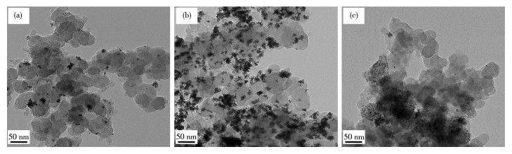
To further demonstrate the effect of Pt/C types on Pt NW cathode morphology, TEM analysis was con-ducted on the powders scraped from each cathode. Fig. 6 confirms that the TEM results are in perfect agreement with the SEM results. Using 20% Pt/C as Pt NP source, Pt seeds in the matrix were relatively dispersed, leading to much shorter Pt NWs and more dispersed Pt nanoaggregates. In the case of 40% Pt/C, the seed distribution reached an appropriate situation, resulting in more uniformly distributed Pt nanoaggre-gates on the carbon spheres. While in the 60% Pt/C case, the Pt seeds were relatively dense in some local areas and most Pt nanostructures concentrated on the Pt seed-rich areas of the matrix, forming seriously agminated Pt nanoaggregates.
Figure 6
Figure 6.
TEM images of Pt NWs grown on carbon matrix mixed with (a) 20% Pt/C, (b) 40% Pt/C, and (c) 60% Pt/C
Pt NP loading, Pt NW loading, and carbon loading of all samples were 0.005, 0.2, and 0.1 mg·cm-2, respectively
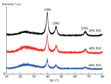
To illustrate the influence of Pt NP sources on Pt NW crystallinity, the XRD patterns of the Pt NW cath-odes with 20%, 40%, and 60% Pt/C were measured and plotted as shown in Fig. 7. It is observed that all XRD patterns of the samples were also similar with the bulk platinum and Pt characteristic peaks appearing at almost the same 2θ. value corresponding to the (111), (200), and (220) facets. The samples with 20% and 40% Pt/C as Pt NP sources had sharper and more intense peaks of the (111) facet than that of the sample with 60% Pt/C as Pt NP source, which means the crys-tallinity of Pt NWs peeled off from the first two samples are better than the latter. This is because most Pt NWs in the 60% Pt/C competitively grew in the limited Pt seed-rich areas and interact with each other. This result is in agreement well with TEM results in Fig. 6 and indicates that Pt NP distribution in the mixed matrix also affects the Pt NW crystallinity like the over-all Pt contents.
Figure 7
Figure 7.
Powder XRD patterns of the Pt NW cathodes with 20%, 40%, and 60% Pt/C
Pt NP loading, Pt NW loading, and carbon loading of all samples were 0.005, 0.2, and 0.1 mg·cm-2, respectively
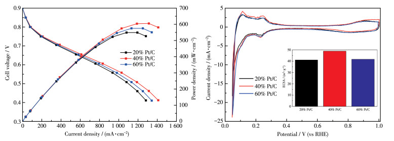
The polarization curves, CV curves, and the main performance data of various cathodes with different types of Pt/C are shown in Fig. 8a, 8b, and Table 2, respectively. The Pt NP loading was fixed at 0.005 mg· cm-2 for all cathodes. Due to the different types of Pt/C, total carbon loading in the matrix for each cathode was slightly different, which was 0.120, 0.108, and 0.103 mg·cm-2 for 20%, 40%, and 60% Pt/C cases, respec-tively. Therefore, the thickness ratio of the three catalyst layers was roughly 100∶90∶86. As shown in Fig. 8a, the cathode with 40% Pt/C had the best cell performance with a current density of 0.86 A·cm-2 at 0. 6 V; this was about 10.3% and 6.2% higher than that of the cathodes with 20% and 60% Pt/C, respectively. For 20% Pt/C, the cell experienced a great decline in performance at high current density. This is attributed to low Pt utilization due to uneven Pt NW distribution and high mass transfer resistance due to a relatively thicker cathode. For 60% Pt/C, the cell performance was considerably worse than that of 40% Pt/C. This is mainly due to the underuse of Pt out of uneven Pt NW distribution. Fig. 8b reveals that the ECSA values of cathode using 20% and 60% Pt/C as Pt seeds were smaller than that of cathode using 40% Pt/C. For 20% Pt/C, this happens because overdispersed Pt NPs lead to an overdispersed distribution of Pt NWs. On the con-trary, for 60% Pt/C case, this is because the overcon-centrated Pt seeds lead to seriously aggregated Pt prod-ucts in Pt seed-rich areas, decreasing the effective utili-zation of Pt. The single-cell performance and CV results of each cathode fit nicely with the microstruc-ture of itself.
Figure 8
Figure 8.
(a) Polarization curves and (b) CV curves of cathodes with different types of Pt/C
Inset in b: ECSA values of corresponding cathodes; Pt NP loading, Pt NW loading, and carbon loading of all cathodes were 0.005, 0.2, and 0.1 mg·cm-2, respectively
2.3
Mechanism for the influence of Pt seed on Pt NW growth
The above results emphasized the significant role of the pre-existing Pt NPs in the matrix. Nevertheless, crystallization and crystal growth are complex process-es, especially with the presence of preformed seeds in solution. Normally, the formation of nanocrystals in a wet chemical reduction reaction contains two basic crystallization and crystal growth are complex process-es, especially with the presence of preformed seeds in solution. Normally, the formation of nanocrystals in a wet chemical reduction reaction contains two basic steps: (i) nucleation and (ii) growth. According to the classical nucleation theory, there is homogeneous and heterogeneous nucleation in wet-chemical synthesis. Homogeneous nucleation occurs when nuclei form uni-formly throughout the parent phase, whereas, heteroge-neous nucleation forms at structural inhomogeneities (container surfaces, impurities, grain boundaries, dislo-cations)[43]. The presence of foreign substances in con-tact with the liquid can significantly lower the free energy barrier, and therefore heterogeneous nucleation is always kinetically more favorable than homogeneous nucleation[44]. As a typical example of heterogeneous nucleation, a seed-mediated method is a common approach for crystal growth either to bypass spontane-ous nucleation or to uncouple nucleation from crystal growth[45]. Early in the 2 000 s, this method has been developed into a versatile approach to control the shapes of noble metal nanocrystals (NCs)[46]. Monocrys-talline polyhedra with various morphologies can be obtained under the control of the process parameters by manipulating the seed structure in the nucleation stage[47]. Besides, a capping agent with selectivity to a particular facet and proper concentration is used in the formation of NC polyhedron and formic acid can act as both of reducing and capping agent[48].
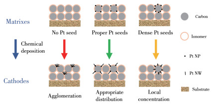
In this study, Pt/C with different Pt weighting ratios were adopted as seeds to investigate the effects of Pt NPs densities under a relatively high formic acid concentration. Fig. 9 shows Pt NW growth under differ-ent Pt NP density conditions. Without preformed Pt NPs in the matrix, only limited rough sites on the sur-face of inert carbon spheres and the junction positions of each single carbon sphere or carbon aggregate are favorable for the heterogeneous nucleation of Pt NWs. Once a few Pt nuclei are formed in some of these sites, the newly reduced Pt atoms will tend to accumulate around there instead of forming new nuclei at other pos-sible nucleation sites. Therefore, the cathode without preformed Pt NPs has an uneven Pt NW distribution as shown in Fig. 1a and low single-cell performance as shown in Fig. 4. In the case of a moderate Pt NP density like 0.005 mg·cm-2 in the matrix, there are enough active nucleation sites for Pt growth and much more primary Pt nuclei could form at the same time than the pure carbon case. Therefore, the newly formed Pt atoms have more available positions for deposition. The Pt distribution of the corresponding cathode can be much more uniform, leading to a higher Pt utilization and better cell performance. When the Pt NP contents are too high (e.g. 0.015 mg·cm-2), the active nucleation sites for Pt NW growth are excessive while the total Pt atom amount is a constant value. As a result, not all the Pt NWs can achieve a good crystallinity as shown in Fig. 3. This is due to that the allocated"raw material" for every single NC is not enough. Too high Pt NP load-ing will lead to a villus-like morphology of the Pt NW cathode[49]. In the Pt/C type investigation, the Pt NP loading in the matrix was fixed at 0.005 mg·cm-2 and three types of Pt/C with different Pt fractions were used to study the influence of local Pt NP densities. For 20% Pt/C, the SEM analysis showed that the Pt NW aggregates achieved a relatively worse distribution than that of the 40% Pt/C case, which inhibits the effective utilization of Pt when the cathode was applied in a practical fuel cell. This phenomenon is due to that Pt NPs on 20% Pt/C are distributed sporadically. The microstructural analysis is in good agreement with the performance and ECSA results shown in Fig. 8. When the 60% Pt/C was added into the matrix as seeds, the average distance between every Pt NP on carbon spheres became too small. This situation causes a high Pt NP density in a local geometric region but a low Pt NP density in other geometric regions. The newly formed Pt species mainly concentrated in the Pt seed-rich areas but hardly arise in Pt seed-poor areas as shown in Fig. 6c. Meanwhile, these local Pt seed-rich areas also cause a low crystallinity of the Pt NWs as shown in Fig. 7 for a similar reason for the high Pt NP content case. To sum up, 0.005 mg·cm-2 is a proper Pt seed amount, and 40% Pt/C is an appropriate Pt seed source to achieve a good Pt NW distribution when high formic acid concentration is adopted in the chemical deposition process.
Figure 9
Figure 9.
Schematic diagram of Pt NW growth under conditions of various Pt seed distributions in the matrix
In this work, the effects of the preformed Pt NPs on the morphology and performance of Pt NW cathode were studied. In a pure carbon matrix, there were limit-ed nucleation sites for heterogeneous nucleation of Pt NWs. The added Pt NPs not only provided more nucle-ation sites to reduce Pt NWs aggregation but also cata-lyzed Pt reduction during the in.-situ. deposition process for a favorable Pt NW nanostructure, which promoted the cell performance of the cathode. The best cell per-formance was obtained with the cathode using a Pt NP loading of 0.005 mg·cm-2, which performed 0.86 A · cm-2 at 0.6 V, being 21% higher than that of the cell without Pt NP loading. Among three types of Pt/C (20%, 40%, and 60%) acting as Pt seed sources, 40% Pt/C achieved proper local Pt NP distribution in the matrix, obtaining a cathode with the best Pt NW distri-bution and single-cell performance, while 20% Pt/C led to a scattered distribution of Pt NW aggregates due to the sporadically distributed Pt NP in the matrix and 60% Pt/C led to a serious accumulation and low crys-tallinity of Pt nanoaggregates in the local Pt seed-rich areas due to uneven seed distribution. Finally, a mech-anism for the influence of Pt NPs in the Pt NW distri-bution was proposed. This work provides a new tech-nique for the controlled growth of Pt NWs in a confined geometry as well as a direction for further improving Pt NW cathode.
Acknowledgments:
This work was financially supported by the National Natural Science Foundation of China (Grants No. 51774145, 21576164, 52074130). We also thank Niyi Olukayode for his grammar editing in the manuscript.
[1]
Meng X T, Deng X, Zhou L S, Hu B, Tan W Y, Zhou W, Liu M L, Shao Z P. A Highly Ordered Hydrophilic -Hydrophobic Janus Bi-functional Layer with Ultralow Pt Loading and Fast Gas/Water Trans-port for Fuel Cells. Energy Environ[J]. Mater.,
2021, 4(1):
126-133.
[2]
赵叙言, 吴宇恩. 高活性、低载量的PtCo/C质子交换膜燃料电池催化剂的合成[J]. 无机化学学报,
2021,37,(8): 1457-1464.
ZHAO X Y, WU Y E. Synthesis of High-Performance and Low-Loading PtCo/C Proton Exchange Membrane Fuel Cell Catalysts[J]. Chinese J. Inorg. Chem.,
2021, 37(8):
1457-1464.
[3]
Garapati M S, Sundara R.. .Highly Efficient and ORR Active Platinum-Scandium Alloy -Partially Exfoliated Carbon Nanotubes Electrocata-lyst for Proton Exchange Membrane Fuel Cell. Int[J]. J. Hydrogen Energy,
2019, 44(21):
10951-10963.
doi: 10.1016/j.ijhydene.2019.02.161
[4]
Zhang H X, Liang J Y, Xia B W, Du S F. Ionic Liquid Modified Pt/C Electrocatalysts for Cathode Application in Proton Exchange Mem-brane Fuel Cells[J]. Front. Chem. Sci. Eng.,
2019, 13(4):
695-701.
doi: 10.1007/s11705-019-1838-8
[5]
Li W B, Lin R, Yang Y. Investigation on the Reaction Area of PEMFC at Different Position in Multiple Catalyst Layer[J]. Electrochim. Acta,
2019, 302:
241-248.
doi: 10.1016/j.electacta.2019.02.003
[6]
Wu Z Y, Iqbal Z, Wang X Q. Metal-Free, Carbon-Based Catalysts for Oxygen Reduction Reactions[J]. Front. Chem. Sci. Eng.,
2015, 9(3):
280-294.
doi: 10.1007/s11705-015-1524-4
[7]
Liu Z Y, Zhang J L, Yu P T, Zhang J X, Makharia R, More K L, Stach E A. Transmission Electron Microscopy Observation of Corrosion Behaviors of Platinized Carbon Blacks under Thermal and Electro-chemical Conditions[J]. J. Electrochem. Soc.,
2010, 157(6):
B906-B913.
doi: 10.1149/1.3391737
[8]
Lu Y X, Du S F, Steinterger-Wilckens R.. One-Dimensional Nano-structured Electrocatalysts for Polymer Electrolyte Membrane Fuel Cells-A Review.[J]. Appl. Catal. B,
2016, 199:
292-314.
doi: 10.1016/j.apcatb.2016.06.022
[9]
Xia Y N, Yang P D, Sun Y G, Wu Y Y, Mayers B, Gates B, Yin Y D, Kim F, Yan H Q. One-Dimensional Nanostructures: Synthesis, Char-acterization, and Applications[J]. Adv. Mater.,
2003, 15(5):
353-389.
doi: 10.1002/adma.200390087
[10]
Cademartiri L, Ozin G A. Ultrathin Nanowires-A Materials Chemistry Perspective[J]. Adv. Mater.,
2009, 21(9):
1013-1020.
doi: 10.1002/adma.200801836
[11]
Zhang J T, Li C M. Nanoporous Metals: Fabrication Strategies and Advanced Electrochemical Applications in Catalysis, Sensing and Energy Systems[J]. Chem. Soc. Rev.,
2012, 41(21):
7016-7031.
doi: 10.1039/c2cs35210a
[12]
Koenigsmann C, Zhou W P, Adzic R R, Sutter E, Wong S S.. Size-Dependent Enhancement of Electrocatalytic Performance in Rela-tively Defect -Free, Processed Ultrathin Platinum Nanowires.[J]. Nano Lett,
2010, 10(8):
2806-2811.
doi: 10.1021/nl100718k
[13]
Xu L B, Yan Y S, Zhang C W, Chen J F. Controlled Synthesis of Pt Nanowires with Ordered Large Mesopores for Methanol Oxidation Reaction[J]. Sci. Rep.,
2016, 6:
31440.
doi: 10.1038/srep31440
[14]
Wang C Z, Zhang Y, Zhang Y J, Xu P, Feng C M, Chen T, Guo T, Yang F N, Wang Q, Wang J X. Highly Ordered Hierarchical Pt and PtNi Nanowire Arrays for Enhanced Electrocatalytic Activity toward Methanol Oxidation[J]. ACS Appl. Mater. Interfaces,
2018, 10(11):
9444-9450.
doi: 10.1021/acsami.7b19727
[15]
Li C L, Sato T, Yamauchi Y. Electrochemical Synthesis of One-Dimensional Mesoporous Pt Nanorods Using the Assembly of Surfac-tant Micelles in Confined Space[J]. Angew. Chem.,
2013, 125(31):
8208-8211.
doi: 10.1002/ange.201303035
[16]
Sun S H, Yang D Q, Zhang G X, Sacher E, Dodelet J P. Synthesis and Characterization of Platinum Nanowire-Carbon Nanotube Heter-ostructures[J]. Chem. Mater.,
2007, 19(26):
6376-6378.
doi: 10.1021/cm7022949
[17]
Sun S H, Yang D, Villers D, Zhang G X, Sacher E, Dodelet J P. Template-and Surfactant-Free Room Temperature Synthesis of Self-Assembled 3D Pt Nanoflowers from Single-Crystal Nanowires[J]. Adv. Mater.,
2008, 20(3):
571-574.
doi: 10.1002/adma.200701408
[18]
Sun S H, Jaouen F, Dodelet J P. Controlled Growth of Pt Nanowires on Carbon Nanospheres and Their Enhanced Performance as Elec-trocatalysts in PEM Fuel Cells[J]. Adv. Mater.,
2008, 20(20):
3900-3904.
doi: 10.1002/adma.200800491
[19]
Sun S H, Zhang G X, Geng D S, Chen Y Q, Li R Y, Cai M, Sun X L. A Highly Durable Platinum Nanocatalyst for Proton Exchange Membrane Fuel Cells: Multiarmed Starlike Nanowire Single Crystal[J]. Angew. Chem,
2011, 123(2):
442-446.
doi: 10.1002/ange.201004631
[20]
Meng H, Zhan Y, Zeng D, Zhang X X, Zhang G Q, Jaouen F. Factors Influencing the Growth of Pt Nanowires via Chemical Self-Assembly and Their Fuel Cell Performance[J]. Small,
2015, 11(27):
3377-3386.
doi: 10.1002/smll.201402904
[21]
Du C Y, Cheng X Q, Yang T, Yin G P, Shi P F. Numerical Simula-tion of the Ordered Catalyst Layer in Cathode of Proton Exchange Membrane Fuel Cells[J]. Electrochem. Commun.,
2005, 7(12):
1411-1416.
doi: 10.1016/j.elecom.2005.09.022
[22]
Bonnefont A, Ruvinskiy P, Rouhet M, Orfanidi A, Neophytides S, Savinova E. Advanced Catalytic Layer Architectures for Polymer Electrolyte Membrane Fuel Cells[J]. WIREs Energy Environ.,
2014, 3(5):
505-521.
doi: 10.1002/wene.110
[23]
Tian Z Q, Lim S H, Poh C K, Tang Z, Xia Z T, Luo Z Q, Shen P K, Chua D, Feng Y P, Shen Z X. A. Highly Order -Structured Membrane Electrode Assembly with Vertically Aligned Carbon Nanotubes for Ultra-Low Pt Loading PEM Fuel Cells[J]. Adv. Energy Mater.,
2011, 1(6):
1205-1214.
doi: 10.1002/aenm.201100371
[24]
Du S F. A Facile Route for Polymer Electrolyte Membrane Fuel Cell Electrodes with In Situ Grown Pt Nanowires[J]. J. Power Sources,
2010, 195(1):
289-292.
doi: 10.1016/j.jpowsour.2009.06.091
[25]
Su K H, Sui S, Yao X Y, Wei Z X, Zhang J L, Du S F. Controlling Pt Loading and Carbon Matrix Thickness for a High Performance Pt-Nanowire Catalyst Layer in PEMFCs[J]. Int. J. Hydrogen Energy,
2014, 39(7):
3397-3403.
doi: 10.1016/j.ijhydene.2013.12.062
[26]
Wei Z X, He A, Su K H, Sui S.. Carbon Matrix Effects on the Micro-Structure and Performance of Pt Nanowire Cathode Prepared by Decal Transfer Method.[J]. J. Energy Chem,
2015, 24(2):
213-218.
doi: 10.1016/S2095-4956(15)60303-5
[27]
Jana N R, Gearheart L, Murphy C J.. Evidence for Seed-Mediated Nucleation in the Chemical Reduction of Gold Salts to Gold Nanoparticles[J]. Chem. Mater.,
2001, 13(7):
2313-2322.
doi: 10.1021/cm000662n
[28]
Zhao X J, Luo X J, Bazuin C G, Masson J F. In Situ Growth of AuNPs on Glass Nanofibers for SERS Sensors[J]. ACS Appl. Mater. Interfaces,
2020, 12(49):
55349-55361.
doi: 10.1021/acsami.0c15311
[29]
Kuttner C, Mayer M, Dulle M, Moscoso A, López-Romero J M, Förster S, Fery A, Pérez-Juste J, Contreras -Cáceres R. Seeded Growth Synthesis of Gold Nanotriangles: Size Control, SAXS Analy-sis, and SERS Performance[J]. ACS Appl. Mater. Interfaces,
2018, 10(13):
11152-11163.
doi: 10.1021/acsami.7b19081
[30]
Tangeysh B, Tibbetts K M, Odhner J H, Wayland B B, Levis R J. Gold Nanotriangle Formation through Strong-Field Laser Processing of Aqueous KAuCl4 and Postirradiation Reduction by Hydrogen Per-oxide[J]. Langmuir,
2017, 33(1):
243-252.
doi: 10.1021/acs.langmuir.6b03812
[31]
Ooi M J, Aziz A A. Seed -Mediated Grown Platinum Nanocrystal: A Correlation between Seed Volume and Catalytic Performance of For-mic Acid and Ethanol Oxidation[J]. Int. J. Hydrogen Energy,
2017, 42(14):
9063-9068.
doi: 10.1016/j.ijhydene.2016.06.032
[32]
Lu Y X, Du S F, Steinberger-Wilckens R. Three-Dimensional Cata-lyst Electrodes Based on PtPd Nanodendrites for Oxygen Reduction Reaction in PEFC Applications[J]. Appl. Catal. B,
2016, 187:
108-114.
doi: 10.1016/j.apcatb.2016.01.019
[33]
Wang R Q, Cao X L, Sui S, Li B, Li Q F. Study on the Growth of Plat-inum Nanowires as Cathode Catalysts in Proton Exchange Membrane fuel cells[J]. Front. Chem. Sci. Eng.,
2022, 16:
364-375.
doi: 10.1007/s11705-021-2052-z
[34]
Berhault G, Bausach M, Bisson L, Becerra L, Thomazeau C, Uzio D.. Seed-Mediated Synthesis of Pd Nanocrystals: Factors Influencing a Kinetic-or Thermodynamic -Controlled Growth Regime[J]. J. Phys. Chem. C,
2007, 111(16):
5915-5925.
doi: 10.1021/jp0702752
[35]
Lee E P, Chen J Y, Yin Y D, Campbell C T, Xia Y N. Pd-Catalyzed Growth of Pt Nanoparticles or Nanowires as Dense Coatings on Poly-meric and Ceramic Particulate Supports[J]. Adv. Mater.,
2006, 18(24):
3271-3274.
doi: 10.1002/adma.200601070
[36]
Du S F, Pollet B G.. Catalyst Loading for Pt -Nanowire Thin Film Electrodes in PEFCs[J]. Int. J. Hydrogen Energy,
2012, 37(23):
17892-17898.
doi: 10.1016/j.ijhydene.2012.08.148
[37]
Zheng J, Zhou S Y, Gu S, Xu B J, Yan Y S. Size-Dependent Hydro-gen Oxidation and Evolution Activities on Supported Palladium Nanoparticles in Acid and Base[J]. J. Electrochem. Soc.,
2016, 163(6):
F499-F506.
doi: 10.1149/2.0661606jes
[38]
Lee W J, Bera S, Shin H C, Hong W P, Oh S J, Wan Z X, Kwon S H. Uniform and Size-Controlled Synthesis of Pt Nanoparticle Catalyst by Fluidized Bed Reactor Atomic Layer Deposition for PEMFCs[J]. Adv. Mater. Interfaces,
2019, 6(21):
1901210.
doi: 10.1002/admi.201901210
[39]
Lee W J, Bera S, Woo H J, Ahn J W, Bae J S, Oh I K, Kwon S H. Controllable Size and Crystallinity of Ru Nanoparticles on Carbon Support by Fluidized Bed Reactor-Atomic Layer Deposition for Enhanced Hydrogen Oxidation Activity[J]. J. Mater. Chem. A,
2021, 9:
17223-17230.
doi: 10.1039/D1TA03678E
[40]
Hou Y Z, Deng H, Pan F W, Chen W M, Du Q, Jiao K.. Pore-Scale Investigation of Catalyst Layer Ingredient and Structure Effect in Proton Exchange Membrane Fuel Cell[J]. Appl. Energy,
2019, 253:
113561.
doi: 10.1016/j.apenergy.2019.113561
[41]
Lu Y X, Du S F, Steinberger -Wilckens R.. Temperature-Controlled Growth of Single -Crystal Pt Nanowire Arrays for High Performance Catalyst Electrodes in Polymer Electrolyte Fuel Cells[J]. Appl. Catal. B,
2015, 164:
389-395.
doi: 10.1016/j.apcatb.2014.09.040
[42]
Baricci A, Bonanomi M, Yu H, Guetaz L, Maric R, Casalegno A. Modelling Analysis of Low Platinum Polymer Fuel Cell Degradation under Voltage Cycling: Gradient Catalyst Layers with Improved Durability[J]. J. Power Sources,
2018, 405:
89-100.
doi: 10.1016/j.jpowsour.2018.09.092
[43]
Thanh N T, Maclean N, Mahiddine S. Mechanisms of Nucleation and Growth of Nanoparticles in Solution[J]. Chem. Rev.,
2014, 114(15):
7610-7630.
doi: 10.1021/cr400544s
[44]
Sosso G C, Chen J, Cox S J, Fitzner M, Pedevilla P, Zen A, Michae-lides A. Crystal Nucleation in Liquids: Open Questions and Future Challenges in Molecular Dynamics Simulations[J]. Chem. Rev.,
2016, 116(12):
7078-7116.
doi: 10.1021/acs.chemrev.5b00744
[45]
Chayen N E. Methods for Separating Nucleation and Growth in Protein Crystallization[J]. Prog. Biophys. Mol. Biol.,
2005, 88(3):
329-337.
doi: 10.1016/j.pbiomolbio.2004.07.007
[46]
Nikoobakht B, El-Sayed M A. Preparation and Growth Mechanism of Gold Nanorods (NRs) Using Seed-Mediated Growth Method[J]. Chem. Mater.,
2003, 15(10):
1957-1962.
doi: 10.1021/cm020732l
[47]
Xiong Y, Xiao L, Yang Y, DiSalvo F J, Abruña H D. High-Loading Intermetallic Pt3 Co/C Core-Shell Nanoparticles as Enhanced Activity Electrocatalysts toward the Oxygen Reduction Reaction (ORR)[J]. Chem. Mater.,
2018, 30(5):
1532-1539.
doi: 10.1021/acs.chemmater.7b04201
[48]
Wang L, Wang H J, Nemoto Y, Yamauchi Y. Rapid and Efficient Synthesis of Platinum Nanodendrites with High Surface Area by Chemical Reduction with Formic Acid[J]. Chem. Mater.,
2010, 22(9):
2835-2841.
doi: 10.1021/cm9038889
[49]
Su K H, Yao X Y, Sui S, Wei Z X, Zhang J L, Du S F. Matrix Material Study for In Situ Grown Pt Nanowire Electrocatalyst Layer in Proton Exchange Membrane Fuel Cells (PEMFCs)[J]. Fuel Cells,
2015, 15(3):
449-455.
doi: 10.1002/fuce.201400168
Figure 1
TEM images with different magnifications of Pt NWs grown on different matrixes, with Pt NPs loading of (a-c) 0 mg·cm-2 and (d-f) 0.005 mg·cm-2, respectively
Pt NW loading and carbon loading of all samples were 0.2 and 0.1 mg·cm-2, respectively
Figure 5
Top-view SEM images with different magnifications of Pt NW cathodes grown on matrix, with various Pt/C types of (a, b) 20% Pt/C, (c, d) 40% Pt/C, and (e, f) 60% Pt/C as Pt NPs sources
Pt NP loading, Pt NW loading, and carbon loading of all samples were 0.005, 0.2, and 0.1 mg·cm-2, respectively
Figure 8
(a) Polarization curves and (b) CV curves of cathodes with different types of Pt/C
Inset in b: ECSA values of corresponding cathodes; Pt NP loading, Pt NW loading, and carbon loading of all cathodes were 0.005, 0.2, and 0.1 mg·cm-2, respectively

 下载:
下载:


 下载:
下载:


 下载:
下载:
