 Figure 1.
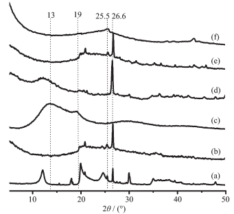
XRD patterns of HNTs (a), HNTs-550 (b), PVA (c), PVA-nanocasted HNTs (d), C-nanocasted HNTs (e) and as-prepared CNRs (f)
Figure 1.
XRD patterns of HNTs (a), HNTs-550 (b), PVA (c), PVA-nanocasted HNTs (d), C-nanocasted HNTs (e) and as-prepared CNRs (f)
Citation:
LIU Zan, LIU Ying-Ying, CHENG Zhi-Lin. HNTs-Templated Preparation of Carbon Nanorods by Hydrothermal Nanocasting Method[J]. Chinese Journal of Inorganic Chemistry,
2017, 33(4): 679-684.
doi:
10.11862/CJIC.2017.032

水热纳米浇筑HNTs模板法制备碳纳米棒
English
HNTs-Templated Preparation of Carbon Nanorods by Hydrothermal Nanocasting Method
Abstract:
A novel method to prepare carbon nanorods through hydrothermal nanocasting method was presented using halloysite nanotubes (HNTs) as the template and polyvinyl alcohol (PVA) as the carbon source. This method involved in three steps, i.e. nanocasting PVA in HNTs, carbonization and etching removal of template. A series of characterization, such as XRD, FT-IR, SEM, TEM, Raman, XPS, SAED and N2 adsorption-desorption were used to detect the formation and structure of the as-prepared carbon nanorods (CNRs). The CNRs with a 1D rod-like structure were of high specific surface area (408 m2·g-1) and possessed typical mesoporous characterization.
-
Key words:
- carbon materials
- / nanorods
- / halloysite nanotubes
- / nanocasting
-
0 Introduction
Carbon nanorods have attracted great interest from past few decades owing to their promising physical and chemical properties. The carbon nanorods are expected to have similar chemical properties of carbon nanotubes, which might find potential applications such as catalyst carriers[1], electrodes[2] and composites[3]. To date, various methods have been demonstrated for the synthesis of carbon nanorods, which include the arc discharge method[4], the chemical vapor deposition[5], the template methods[6], the electron beam-induced route[7], the reduction of carbon bisulfide[8] and the catalytic copyrolysis method[9].
Recently, the templated synthesis via the nano-replication route appears to be a versatile method to build nanomaterials with high surface area and special porous nanostructure. Tang et al.[10] reported a modified nanocasting method to synthesize manganese oxide by SBA-15 template. The mixed oxide with a higher surface area exhibited a highest activity with 90% benzene conversion at 250 ℃ under a high space velocity. Barrera et al.[11] synthesized nanostructured carbons by a nanocasting method, using a very ordered mesoporous material (SBA-15) as template and sucrose as carbon source. The final material consists of an ordered arrangement of parallel carbon nanorods bonded with some carbon nanowires (CMK-3 type), formed in the mesopores and micropores of the inorganic matrix.
Among other nanotemplates, halloysite nanotubes (HNTs) as naturally available aluminosilicate clay with ca. 15 nm in lumen diameter and 600~1500 nm in length, can become a promising candidate for nano-confined template because of its well-defined hollow tubular structure, abundance in nature as a raw material, and the increasing demand for the environment-friendly products[12]. So far, it has been used for encapsulation and sustained-release of different chemical agents, such as proteins, drugs, antiseptics, antimicrobial agents, and corrosion inhibi-tors for metal protection[13-19]. Mu et al.[20] fabricated silver/halloysite nanotube/Fe3O4 (Ag/HNT/Fe3O4) nano-composites by selective modification of the lumen of halloysite nanotubes with silver nanorods and the external wall with Fe3O4 nanoparticles, which exhibited an excellent catalytic activity and recyclability for the reduction of 4-nitrophenol to 4-aminophenol by NaBH4. Abdullayev et al.[21] synthesized silver nanorods inside the lumen of the halloysite by thermal decomposition of the silver acetate, which was loaded into halloysite from an aqueous solution by vacuum cycling.
Herein, we present a templated hydrothermal technique to prepare carbon nanorods (CNRs) employ-ing halloysite nanotubes (HNTs) as template and polyvinyl alcohol (PVA) as carbon source. The forma-tion and structure of as-prepared CNRs was deter-mined by a series of characterizations.
1 Experimental
1.1 Synthesis of carbon nanorods
Before using, HNTs (200~500 nm in length and 15~25 nm in pore diameter, purchased from Golden Sun Ceramics Co., Ltd. in China) were calcined at 550 ℃ for 6 h in air, denoted HNT-550. 1.5 g of the calcined HNTs was dried at 100 ℃ for at least 24 h in a drying oven. According to the mPVA/mHNTs of 2:1, HNTs powder were added into 15% PVA aqueous solution and stirred for 2 h. Then, the mixture solution was transferred into an autoclave and put into an oven to keep hydrothermal treatment at 180 ℃ for 18 h. After ending, the product was filtered and washed, denoted PVA-nanocasted HNTs. Subsequently, the above obtained product was carbonized at 700 ℃ for 3 h under N2 atmosphere in a tube furnace, denoted C-nanocasted HNTs. Finally, the C-nanocasted HNTs were etched by 40% HF solution to remove the HNTs template completely. The insoluble solid was obtained, denoted CNRs.
1.2 Characterization
XRD patterns were obtained with D8 Advance X-ray diffraction in 2θ range of 5°~70° with operation condition at 40 kV and 30 mA (Cu Kα, λ=0.154 nm). TEM images were recorded by Tecnai 12 transmission electron microscope. SEM images were recorded by S-4800 Scanning Electron Microscope (15 kV). XPS was recorded by ESCALAB 250Xi X-ray photoelectron spectrometer. Raman spectra were acquired on a Labram-1B (Dilor, France) confocal microscopy Raman spectrometer with a 532 nm wavelength incident laser light. N2 adsorption-desorption isotherms were deter-mined by using Sorptomatic 1990 Thermo Finningen instrument.
2 Results and discussion
As shown in XRD patterns (Fig. 1), the typical characteristic peaks of the calcined HNTs (Fig. 1b) in 2θ range of =10°~23° have hardly disappeared, only existing the peak of quartz phase at 26.8°. This suggests that the crystal structure of the nanotube wall of HNTs was destroyed due to happening dehydration[22]. Comp-ared to pure PVA and HNTs, the PVA-nanocasted HNTs (Fig. 1d) have the main characteristic peaks at 12°, 19° and 26.6°, which contain the main feature peaks of pure HNTs and PVA. However, the feature peak at 12° should be assumed to the shift of the feature peak of pure PVA at 13°, hinting that it is likely to exist an interaction between PVA molecular and the surface active group of HNTs in the PVA-nanocasted HNTs[23]. After carbonized at high tempera-ture, the C-nanocasted HNTs are of the similar characteristic peaks with the calcined HNTs (Fig. 1e). As shown in Fig. 1f, the as-prepared CNRs have the feature peaks at 25.5° and 44°, which can be respectively indexed to (002) and (101) diffraction planes corresponding to the hexagonal graphite phase[24]. The two broadened peaks suggest the possible presence of an amorphous carbon phase within the as-prepared CNRs. No impurity in the as-prepared CNRs is observed in the XRD pattern.
Figure 1.
XRD patterns of HNTs (a), HNTs-550 (b), PVA (c), PVA-nanocasted HNTs (d), C-nanocasted HNTs (e) and as-prepared CNRs (f)
Fig. 2 shows the FT-IR spectra of HNTs, PVA, PVA-nanocasted HNTs, C-nanocasted HNTs and as-prepared CNRs. As for the HNTs (Fig. 2a), the peaks at 3 705 and 3 621 cm-1 are assigned to the stretching vibrations of Al-OH groups at the surface of HNTs. The peaks at 1 650 and 1 092 cm-1 are associated with the O-H bending vibration of water and the in-plane stretching vibrations of Si-O[25], respectively. As shown in Fig. 2b, PVA has the characteristic peaks at 2 943 and 2 907 cm-1, which should be ascribed to the C-H (CH2) asymmetric and symmetric stretching, respectively. Furthermore, there also are the peak at 1 437 cm-1 associated with the C-H (CH2) deformation vibration and the broad peak at 3 316 cm-1 assigned to-OH stretching vibration[26]. Compared to pure HNTs and PVA, the PVA-nanocasted HNTs contain the main characteristic peaks of HNTs with PVA (Fig. 2c). After carbonization at high temperature, the spectrum of the C-nanocasted HNTs have lost most of the characteristic peaks of pure HNTs and PVA, and only remain the feature peaks of Si-O groups (Fig. 2d). No organic group originated from PVA is observed, indicating that the nanocasting PVA molecular was completely graphitized. The as-prepared CNRs possess the characteristic peaks at 1 161 and 1 222 cm-1 associated with the C-O stretching vibration, and the peak at 1 564 cm-1 assigned to the C=C stretching vibration[27-29]. It indicates that the as-prepared CNRs materials have been successfully achieved by this method.
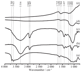 Figure 2.
FT-IR spectra of HNTs (a), PVA (b), PVA-nanocasted HNTs (c), C-nanocasted HNTs (d) and as-prepared CNRs (e)
Figure 2.
FT-IR spectra of HNTs (a), PVA (b), PVA-nanocasted HNTs (c), C-nanocasted HNTs (d) and as-prepared CNRs (e)
Fig. 3 and Fig. 4 display the SEM and TEM images of the products. The HNTs-550 still keep the hollow nanotube structure with ca. 20 nm in diameter and 200~1 000 nm in length (Fig. 3a and Fig. 4a). The SEM and TEM images of the PVA-nanocasted HNTs (Fig. 3b and Fig. 3b) show that PVA has successfully nanocasted in the hollow nanotube of HNTs. As shown in Fig. 3c and Fig. 4c~d, the carbon nanorods derived from the PVA-nanocasted HNTs can be clearly seen, indicating that the large quantity of the carbon nanorods with ca. 20 nm in diameter and 200~800 nm in length were obtained through this approach. The HRTEM and SAED images of the as-prepared CNRs. (Fig. 4e, f) indicate that the as-prepared CNRs consist of the amorphous carbon nanoparticles.
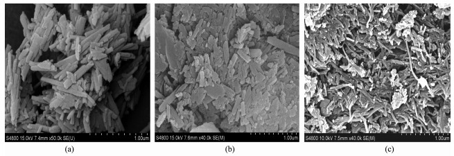 Figure 3.
SEM images of HNTs (a), HNTs-550 (b) and as-prepared CNRs (c)
Figure 3.
SEM images of HNTs (a), HNTs-550 (b) and as-prepared CNRs (c)
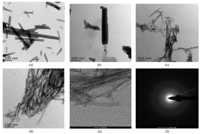 Figure 4.
TEM images of HNTs (a), HNTs-550 (b), CNRs (c); HRTEM picture (h) and SAED pattern of as-prepared CNRs (i)
Figure 4.
TEM images of HNTs (a), HNTs-550 (b), CNRs (c); HRTEM picture (h) and SAED pattern of as-prepared CNRs (i)
The elemental composition of the as-prepared CNRs is determined by XPS as shown in Fig. 5a. The as-prepared CNRs are composed of 91.5% C, 7.2% O and 1.3% S (atom ratio). The curve-fitting of C1s peak demonstrates the presence of bands at 284.8, 285.8, 287 and 288.4 eV, which are originated from graphitic carbon C-C/C=C, C-O, C=O and O-C=O, respectively[30]. As shown in Fig. 5b, the as-prepared CNRs exhibited a D band at around 1 352 cm-1 and a G band at around 1 584 cm-1 in Raman spectrum, which correspond to the graphitic sp2 carbon structure and the disordered structure in sp2-hybridized carbon system[31]. Moreover, the ID/IG value of the as-prepared CNRs is 0.75, indi-cating that as-prepared CNRs have a higher graphi-tization degree and the fewer defects[32].
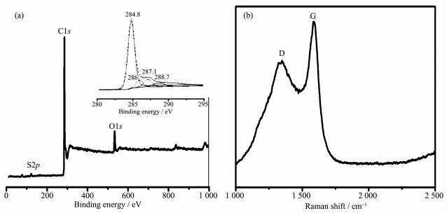 Figure 5.
(a) Survey X-ray photoelectron spectrum and C1s spectrum (inset) of as-prepared CNRs;
(b) Raman spectrum of as-prepared CNRs
Figure 5.
(a) Survey X-ray photoelectron spectrum and C1s spectrum (inset) of as-prepared CNRs;
(b) Raman spectrum of as-prepared CNRs
The nitrogen adsorption-desorption isotherm and pore-size distribution of the products are shown in Fig. 6. As shown in Fig. 6(left), the isotherms of the as-prepared CNRs show a type Ⅳ isotherm and type H3 hysteresis loops[24]. In addition, the appearance of hyst-eresis loops at relative pressure higher than 0.45 indi-cates that the as-prepared CNRs are of the mesoporous structure[33]. The BET specific surface area value of the as-prepared CNRs is up to 408 m2·g-1. As shown in Fig. 6 (right), the BJH pore-size distributions of C-nanocasted HNTs almost lose the hollow nanopore feature of HNTs, confirming that PVA molecular has been successfully nanocasted in the nanotubes of HNTs by dipping method. In addition, it is also revealed that the as-prepared CNRs exist two types of the main mesopores at 3.9 and 13.5 nm, respectively.
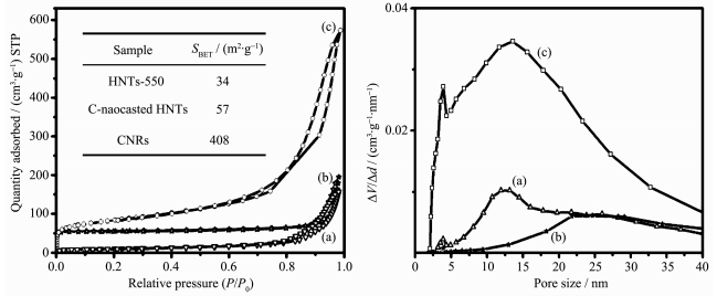 Figure 6.
N2 adsorption isotherms (left) and pore size distribution (right) of HNTs-550 (a), C-nanocasted HNTs (b) and as-prepared CNRs (c)
Figure 6.
N2 adsorption isotherms (left) and pore size distribution (right) of HNTs-550 (a), C-nanocasted HNTs (b) and as-prepared CNRs (c)
3 Conclusions
The carbon nanorods were successfully synth-esized by hydrothermal nanocasting method employing halloysite nanotubes (HNTs) as the template and polyvinyl alcohol (PVA) as the carbon source. The BET specific surface area value of the as-prepared CNRs was up to 408 m2·g-1 and possessed two types of the mesopores at 3.9 nm and 13.5 nm.
-
-
[1]
Patsalas P. Thin Solid Films, 2011, 519:3990-3996 doi: 10.1016/j.tsf.2011.01.202
-
[2]
Wang J, Chen Y, Zhang Y, et al. J. Mater. Chem., 2011, 21:18195-18198 doi: 10.1039/c1jm13796d
-
[3]
Fan Y R, Zhao Z B, Zhou Q, et al. Carbon, 2013, 58:128-133 doi: 10.1016/j.carbon.2013.02.040
-
[4]
Liu Y Q, Hu W P, Wang X B, et al. Chem. Phys. Lett., 2000, 331:31-34 doi: 10.1016/S0009-2614(00)01143-X
-
[5]
Thien-Nga L, Hernadi K, Forro L. Adv. Mater., 2001, 13:148-150 doi: 10.1002/(ISSN)1521-4095
-
[6]
Kleitz F, Choi S H, Ryoo R. Chem. Commun., 2003, 9:2136-2137 http://www.ncbi.nlm.nih.gov/pubmed/13678168
-
[7]
Chen K, Wu C, Hwang J S, et al. J. Phys. Chem. Solids, 2001, 62:1561-1565 doi: 10.1016/S0022-3697(01)00095-6
-
[8]
Lou Z, He M, Zhao D, et al. J. Alloys Compd., 2010, 507:38-41 doi: 10.1016/j.jallcom.2010.07.097
-
[9]
Zou G, Lu J, Wang D, et al. Inorg. Chem., 2004, 43:5432-5435 doi: 10.1021/ic049812c
-
[10]
Tang W, Li J, Wu X, et al. Catal. Today, 2015, 258:148-155 doi: 10.1016/j.cattod.2015.04.023
-
[11]
Barrera D, Dávila M, Cornette V, et al. Microporous Meso-porous Mater., 2013, 180:71-78 doi: 10.1016/j.micromeso.2013.06.028
-
[12]
Yah W O, Xu H, Soejima H, et al. J. Am. Chem. Soc., 2012, 134:12134-12137 doi: 10.1021/ja303340f
-
[13]
Lvov Y M, Shchukin D G, Möhwald H, et al. ACS Nano, 2008, 2:814-820 doi: 10.1021/nn800259q
-
[14]
Abdullayev E, Price R, Shchukin D, et al. ACS Appl. Mater. Interface, 2009, 1:1437-1443 doi: 10.1021/am9002028
-
[15]
Zhai R, Zhang B, Liu L, et al. Catal. Commun., 2010, 12:259-263 doi: 10.1016/j.catcom.2010.09.030
-
[16]
Yuan P, Southon P, Liu Z, et al. J. Phys. Chem. C, 2008, 112:15742-15751 doi: 10.1021/jp805657t
-
[17]
Abdullayev E, Lvov Y. J. Mater. Chem., 2010, 20:6681-6687 doi: 10.1039/c0jm00810a
-
[18]
Zhai H, Sun D, Wang H. J. Nanosci. Nanotechnol., 2006, 6:1968-1792 doi: 10.1166/jnn.2006.320
-
[19]
Lin C, Danaie M, Liu Y, et al. J. Nanosci. Nanotechnol., 2009, 9:4985-4987 doi: 10.1166/jnn.2009.1213
-
[20]
Mu B, Wang W, Zhang J, et al. RSC Adv., 2014, 4:39439-39445 doi: 10.1039/C4RA05892E
-
[21]
Abdullayev E, Sakakibara K, Okamoto K, et al. ACS Appl. Mater. Interface, 2011, 3:4040-4046 doi: 10.1021/am200896d
-
[22]
Du Y, Zheng P. Korean J. Chem. Eng., 2014, 31:2051-2056 doi: 10.1007/s11814-014-0162-8
-
[23]
Lee I W, Li J, Chen X, et al. J. Appl. Polym. Sci., 2015, 133:42900-42911
-
[24]
Zheng R, Mo Z, Liao S, et al. Carbon, 2014, 69:132-141 doi: 10.1016/j.carbon.2013.11.075
-
[25]
Wang L, Chen J, Ge L, et al. Energy Fuels, 2011, 25:3408-3416 doi: 10.1021/ef200719v
-
[26]
Swapna V P, Selvin T P, Suresh K I, et al. Int. J. Plast. Technol., 2015, 19:124-136 doi: 10.1007/s12588-015-9106-3
-
[27]
Yu H. J. Mater. Chem. A, 2013, 1:12198-12205 doi: 10.1039/c3ta12722b
-
[28]
Sha J, Li G, Chen X, et al. Polym. Compos., 2016, 37:870-880 doi: 10.1002/pc.v37.3
-
[29]
Wei Y, Ling X, Zou L, et al. Colloids Surf. A, 2015, 482:507-513 doi: 10.1016/j.colsurfa.2015.07.005
-
[30]
Zhang Z, Pfefferle L, Lhaller G. Chin. J. Catal., 2014, 35(6):856-863 doi: 10.1016/S1872-2067(14)60123-6
-
[31]
Kucukayan G, Ovali R, Ilday S, et al. Carbon, 2011, 49:508-517 doi: 10.1016/j.carbon.2010.09.050
-
[32]
Xu X, Lu Z, Hima H I, et al. Appl. Clay Sci., 2009, 42:405-409 doi: 10.1016/j.clay.2008.04.004
-
[33]
Jiang J, Chen Z, Duanmu C, et al. Mater. Lett., 2014, 132:425-427 doi: 10.1016/j.matlet.2014.06.135
-
[34]
Wang A, Kang F, Huang Z. Microporous Mesoporous Mater., 2008, 108:318-324 doi: 10.1016/j.micromeso.2007.04.021
-
[1]
-

Figure 1 XRD patterns of HNTs (a), HNTs-550 (b), PVA (c), PVA-nanocasted HNTs (d), C-nanocasted HNTs (e) and as-prepared CNRs (f)

Figure 2 FT-IR spectra of HNTs (a), PVA (b), PVA-nanocasted HNTs (c), C-nanocasted HNTs (d) and as-prepared CNRs (e)

Figure 4 TEM images of HNTs (a), HNTs-550 (b), CNRs (c); HRTEM picture (h) and SAED pattern of as-prepared CNRs (i)

Figure 5 (a) Survey X-ray photoelectron spectrum and C1s spectrum (inset) of as-prepared CNRs; (b) Raman spectrum of as-prepared CNRs
-


 下载:
下载:


 扫一扫看文章
计量
- PDF下载量: 1
- 文章访问数: 1323
- HTML全文浏览量: 119
 下载:
下载:
