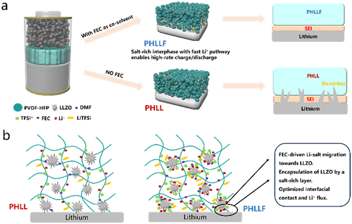
Scheme 1.
Schematic illustration of the ion transport mechanism in PHLLF.

Localized surface segregation of lithium salts enabling fast lithium-ion channels and robust interphases toward stable solid-state lithium batteries
Qilin Zhang , Decai Ji , Wenwei Ding , Qian Ni , Wenjuan Zhu , Chuyang Li , Qingqing Zhou , Bin Wang , Yadong Wang , Zhipeng Liu , Xiang Han


Lithium metal batteries (LMBs) hold great promise for satisfying these energy demands. Still, making them commercially viable requires a structural shift toward solid-state electrolytes (SSEs) [1,2]. This replacement is crucial because solid matrices eliminate the fire hazards associated with traditional liquid cells, while also providing a strong physical barrier against dendrite penetration. Among various SSEs, organic polymer electrolytes offer superior flexibility and electrode compatibility but suffer from insufficient ionic conductivity [3–5]. Conversely, inorganic solid electrolytes exhibit high ionic conductivity at the expense of poor interfacial contact and limited processability [6–8]. Composite solid-polymer electrolytes, which integrate a flexible polymer matrix with high-conductivity inorganic filler, represent a balanced paradigm that synergizes the mechanical robustness of polymers with the rapid ion transport of ceramics, holding great significance for advanced solid-state energy storage [9–11].
Recently, PVDF-based electrolytes containing Li-ion clusters coordinated with residual ligands, such as DMF, have garnered significant attention. In this configuration, Li-ion transport is facilitated through synergistic interactions between these solvated clusters and the PVDF chains [12–14]. Although this enables room-temperature cycling of solid-state LMBs, the intrinsic ionic conductivity remains subpar. To further elevate the conductivity, researchers have incorporated various fast-ion conductors, such as Li6.75La3Zr1.75Ta0.25O12 (LLZTO) [15], Li1.4Al0.4Ti1.6(PO4)3 (LATP) [16], and Li0.35La0.55TiO3 (LLTO) [17], exploring diverse morphologies including nanoparticles, nanowires, and 3D frameworks [18]. Despite their potential, the practical deployment of SPEs still faces a major bottleneck. Their overall performance is heavily restricted by the massive contact resistance that exists between the solid particles and the organic host [19]. The disparate physicochemical properties of these two phases often result in poor interfacial compatibility, triggering phase separation and the formation of space-charge layers [20]. Consequently, Li ions are forced into tortuous migration pathways within the polymer matrix, failing to utilize the high-speed ceramic channels and leading to sluggish ion transport kinetics.
To overcome these interfacial hurdles, various strategies-such as surface grafting [21,22], silane coupling [23,24], and interlayer construction [25] have been proposed to bridge the discrepancy between lithiophilic and lithiophobic phases. While effective to some extent, these methods typically involve complex synthetic procedures or fail to establish a continuous, high-speed ion-conduction network essential for ultra-fast charging [26,27]. Therefore, developing a facile and robust strategy to reconstruct the filler-polymer interface for high-rate performance remains a critical challenge.
Herein, we report a novel interfacial engineering strategy by introducing FEC as a multifunctional structural modulator into the PVDF-HFP/LLZO composite electrolyte. Distinct from its conventional role as merely a sacrificial, SEI-forming additive at the lithium anode, we emphasize a non-consumptive interfacial regulatory function of intact FEC within the bulk electrolyte. Through competitive coordination, FEC effectively shields the ceramic particles from deleterious solvent-induced degradation and modulates the local electrostatic landscape, triggering the localized segregation of lithium salts precisely at the LLZO surface. This in-situ constructed, salt-enriched interphase not only ensures conformal solid-solid wetting to alleviate interfacial incompatibility, but also establishes a continuous, percolated network for accelerated Li+ transport. Thus, the formidable interfacial impedance is significantly dismantled, unlocking the ultimate high-rate potential of the SPE. Consequently, the assembled Li//LiFePO4 (LFP) full cells exhibit exceptional fast-charging capability, delivering 640 stable cycles at an ultra-high rate of 8 C at room temperature, and 400 cycles at 5 C under 50 ℃. Furthermore, the modified SPE demonstrates superior high-voltage compatibility with NCM811 cathodes and maintains stable plating/stripping behavior for over 700 h in Li//Li symmetric cells. This work provides a new perspective on interfacial regulation for the development of high-rate and safe solid-state batteries.
The PHLLF composite electrolyte films were synthesized utilizing a conventional solution-casting approach. Specifically, a homogeneous precursor suspension was formulated by combining 0.6 g of poly(vinylidene fluoride-hexafluoropropylene) (PVDF-HFP, Mw = 400,000, Sigma-Aldrich), 0.6 g of lithium salt (LiTFSI, Canrd), and 0.06 g of active inorganic fillers (LLZO, 400 nm, Canrd). This solid mixture was thoroughly dissolved and dispersed within a binary solvent blend comprising N,N-dimethylformamide (DMF) and fluoroethylene carbonate (FEC), where the FEC proportion was established at 5 wt% relative to the DMF mass. To guarantee complete dissolution and uniform dispersion, the system was subjected to continuous mechanical agitation for 12 h at a constant temperature of 45 ℃. Following this, the well-mixed viscous slurry was smoothly coated onto a pristine glass substrate. To ensure the absolute elimination of any entrapped solvent molecules, the cast film was transferred into a vacuum oven and thermally treated at 60 ℃ for a prolonged duration of 48 h. Serving as a baseline reference, the unmodified PHLL membrane was manufactured mirroring this exact operational sequence, with the strict omission of the FEC additive. Post-drying, the final dimensional thickness for both the PHLL and PHLLF architectures was meticulously calibrated to a controlled range of 100–110 μm.
The preparation of the cathode architecture commenced with the dissolution of the poly(vinylidene fluoride) (PVDF) binder into N,N-dimethylformamide (DMF) to formulate a 5 wt% baseline solution. Following this, the LiFePO4 active material, conductive carbon additive, and the pre-dissolved PVDF were combined at a precise weight proportion of 8:1:1. To ensure optimal homogeneity, N-methyl-2-pyrrolidone (NMP) was introduced as an additional dispersion solvent, and the entire system was subjected to rigorous mechanical agitation. The resulting well-dispersed viscous mixture was subsequently transferred and coated onto an aluminum foil substrate via a standard film applicator. To completely vaporize all remaining solvent molecules, the as-coated films were placed in a heating chamber maintained at 80 ℃ for a continuous 12-h drying phase. Finally, the solvent-free composite laminates were mechanically sectioned into 12 mm diameter disks to serve as the working electrodes for cell assembly.
The preparation of the cathode architecture commenced with the dissolution of the PVDF binder into DMF to formulate a 5 wt% baseline solution. Following this, the NCM811 active material, conductive carbon additive, and the pre-dissolved PVDF were combined at a precise weight proportion of 8:1:1. To ensure optimal homogeneity, NMP was introduced as an additional dispersion solvent, and the entire system was subjected to rigorous mechanical agitation. The resulting well-dispersed viscous mixture was subsequently transferred and coated onto an aluminum foil substrate via a standard film applicator. To completely vaporize all remaining solvent molecules, the as-coated films were placed in a heating chamber maintained at 80 ℃ for a continuous 12-h drying phase. Finally, the solvent-free composite laminates were mechanically sectioned into 12 mm diameter disks to serve as the working electrodes for cell assembly.
Initial evaluations of the membrane morphology and spatial elemental distributions were conducted using a field-emission scanning electron microscope (Model JSM-7600F, JEOL) coupled with an EDS detector. To acquire precise quantitative metrics regarding the local surface roughness, atomic force microscopy scans were performed on a Dimension Edge platform (Bruker). The crystallographic signatures of the as-synthesized solid electrolytes were determined via an X-ray diffraction system (D2 Phaser, Bruker). The instrument utilized a Cu Kα emitter (λ = 0.154 nm) operating at 10 mA and 30 kV, recording diffraction profiles from 5° to 80° at a continuous sweep velocity of 10°/min. For the verification of internal chemical bonding and functional groups, FTIR absorption spectra were collected across the 500–4000 cm-1 range using a Vertex 80 V spectrometer (Bruker). These structural insights were further corroborated by Raman scattering analyses, executed on a Themor diagnostic platform equipped with a 532 nm laser source. To thoroughly resolve the chemical architecture of the SEI formed upon the cycled lithium anodes, X-ray photoelectron spectroscopy measurements were undertaken on an ESCALAB 250 Xi system. The apparatus was powered by a strictly monochromatized Al Kα radiation source (1486.6 eV) driven at 3 mA and 12 kV. Additionally, depth-resolved compositional profiles of the interphase were extracted by employing an alternating Ar+ ion bombardment protocol, which was precisely calibrated to an etching rate of 0.5 nm/s. Regarding macroscopic physical properties, thermal stabilities were continuously monitored employing a Rigaku simultaneous thermal analyzer (Model TG-DTA 8122). The membranes were subjected to a programmed heating regimen from room temperature up to 600 ℃ under an inert argon atmosphere, utilizing a defined heating step of 10 ℃/min. Lastly, the uniaxial tensile behaviors were assessed to quantify the mechanical resilience of the solid polymer electrolytes, utilizing a universal testing machine (UTM2502, SANS).
All the coordination configuration calculations were performed via the first-principles density of functional theory. Li7La3Zr2O12 models were constructed, and their adsorption performance toward DMF and FEC was evaluated by DFT calculations. In the constructed models, the vacuum layer was designed to be more extensive than 15.0 Å to avoid interactions between periodic structural units. The Cambridge serial total energy package (CASTEP) in Materials Studio 2019 (BIOVIA, San Diego, CA), which were based on DFT and the ultrasoft pseudopotential (USP) method, were applied to perform all of the calculations. For the parameter settings, the plane-wave cut-off energy was set at 560 eV, and the energy variation per atom during constant iteration was maintained below 1.0 × 10⁻⁵ eV. The Brillouin zone was sampled using a Monkhorst–Pack k-point mesh of 2 × 2 × 1. The force exerted on each atom was constrained to no > 0.1 eV/Å, while the maximum ion displacement was limited to 0.005 Å. The exchange-correlation energy function was modeled using the Perdew–Burke–Ernzerhof (PBE) version of the generalized gradient approximation (GGA). The adsorption energies (Eads) were calculated as Eads = Ead&sub - Ead - Esub, where Ead&sub, Ead, and Esub were the optimized adsorbate/substrate system, the adsorbate in the structure and the clean substrate, respectively.
For all solid-state electrochemical characterizations, standard CR2025 coin cells were assembled. The entire assembly process took place inside an argon glovebox to prevent environmental contamination, with both oxygen and moisture levels kept strictly below 1 ppm.
To measure the bulk ionic conductivity (σ), the polymer films were placed between a pair of stainless steel (SS) blocking electrodes. Impedance data were then collected using a 10 mV AC signal, scanning across a frequency range from 7 MHz down to 0.1 Hz. The conductivity values were extrapolated using Eq. 1:
|
|
(1) |
herein, L (cm) and S (cm2) are designated as the physical thickness of the SPE and the active interfacial contact area, respectively. Additionally, the parameter R (Ω) signifies the membrane’s bulk resistance, which is extracted directly from the high-frequency real-axis intercept in the Nyquist plot. Furthermore, temperature-dependent conductivities were mapped from 30 ℃ to 80 ℃ and subsequently modeled according to the Arrhenius equation empirical relation to elucidate the migration kinetics. The activation energy (Ea) was derived via Eq. 2:
|
|
(2) |
Within the empirical formulation utilized to model the ionic conductivity, σ0 represents the pre-exponential factor, R denotes the ideal gas constant, T dictates the absolute measurement temperature, and T0 is intrinsically associated with the theoretical glass transition state of the host polymer. To quantitatively evaluate the electrochemical oxidative resistance, asymmetric Li//SS assemblies were subjected to linear sweep voltammetry (LSV), where the applied potential was continuously driven from 2.5 V to 5.0 V (vs. Li/Li+) employing a fixed sweep velocity of 0.5 mV/s. Additionally, the precise quantification of the lithium-ion transport capability, denoted as the transference number (tLi+), was executed using symmetric Li//Li cells in accordance with the established Bruce–Vincent polarization protocol. To quantitatively determine the lithium-ion transference number tLi+, the symmetric assemblies were subjected to a potentiostatic DC bias ΔV = 10 mV. This step was strategically coupled with AC impedance evaluations recorded both before the onset and following the equilibration of the polarization. The tLi+ parameter was deduced according to Eq. 3:
|
|
(3) |
Within this formulation, I0 and ISS denote the instantaneous current response and the ultimate stabilized current, respectively. Concurrently, R0 and RSS signify the interfacial resistance parameters extracted from the impedance spectra prior to the DC voltage application and after reaching the steady state.
To ascertain the maximum operational threshold for stable lithium plating and stripping (commonly denoted as the critical current density), the symmetric Li//Li configurations underwent a stepwise galvanostatic escalation procedure. This testing protocol incrementally amplified the applied current from 0.1 mA/cm2 to 1.0 mA/cm2 under ambient conditions.
The solid-state full battery configurations were constructed by coupling a metallic lithium anode with either an LFP or NCM811 composite cathode, where the active areal mass loading was meticulously regulated between 1.5 mg/cm2 and 2.0 mg/cm2. Long-term galvanostatic charge/discharge behaviors of these assembled cells were continuously recorded on a multi-channel battery testing platform (NEWARE). During these evaluations, the operating potential limits were set from 2.8 V to 3.9 V (vs. Li/Li+) for the Li//LFP system, while the high-voltage Li//NCM811 counterparts were examined within an extended domain of 2.8–4.2 V. To further ascertain the redox reversibility of the LFP-based architectures, cyclic voltammetry (CV) profiles were acquired utilizing an electrochemical workstation (Model VSP-300, Bio-Logic). This voltage sweep was conducted at a strictly controlled rate of 0.2 mV/s across the 2.8–3.9 V window.
Scheme 1 schematically illustrates the synthesis protocols and structural evolution of the PVDF-HFP-LiTFSI-LLZO (PHLL) and PVDF-HFP-LiTFSI-LLZO-5%FEC (PHLLF) electrolytes from both macroscopic and microscopic perspectives. A composite polymer electrolyte was architected via a co-solvent evaporation approach, utilizing commercial garnet-type LLZO [28] as a functional inorganic filler. Benefiting from its wide electrochemical window, decent room-temperature ionic conductivity, and competitive ambient ionic conductivity, LLZO serves as an efficacious component to synergistically compensate for the subpar room-temperature ionic conductivity of the PVDF-HFP matrix [29–31]. To further optimize the interfacial properties, FEC and DMF were employed as co-solvents for the preparation of PHLLF. Owing to the selective solubility, where FEC effectively dissolves LiTFSI but acts as a non-solvent for PVDF-HFP, the rapid evaporation of DMF during the film-casting process triggers the preferential precipitation of the PVDF-HFP polymer. Consequently, the residual FEC, which maintains a high concentration of LiTFSI, preferentially congregates at the LLZO surfaces due to its more negative adsorption energy relative to other components. This localized enrichment creates a salt-rich interfacial layer on the LLZO particles, effectively shielding them from the deleterious coordination between DMF and the LLZO surface sites [32]. By preserving the high-speed ion conduction channels of the LLZO fillers, this engineered architecture provides facilitated pathways for rapid Li+ migration.
Furthermore, the low volatility of FEC promotes the formation of a dense and compact bulk configuration, augmenting the interfacial bonding between LLZO and the PVDF-HFP matrix. Such a process prevents the LLZO particles from aggregating, keeping them evenly distributed throughout the polymer network. This structural uniformity directly improves the physical strength of the composite while also promoting faster internal ion transport. Crucially, the FEC-induced salt enrichment around LLZO significantly improves the solid-solid interfacial wetting between the electrolyte and the lithium metal anode. This strategy enables the effective utilization of LLZO’s high ionic conductivity while circumventing the inherent issues of poor interfacial compatibility. Furthermore, the incorporation of the FEC additive facilitates the in-situ construction of a mechanically resilient, inorganic-dominated SEI. This chemically optimized protective layer fundamentally restrains the propagation of dendritic lithium, thereby endowing the solid-state metal cells with superior prolonged operational endurance.
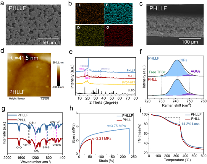
Introducing the FEC additive fundamentally reshapes the internal structural network and modifies the basic physical chemistry of the composite SPE membranes. Morphological evolution was first scrutinized via scanning electron microscopy (SEM). As illustrated in Fig. S1 (Supporting information), the surface of the PHLL baseline is plagued by prominent LLZO macro-aggregates, which inherently compromises the interfacial wetting and effective contact area between the electrolyte and the electrodes [33]. In sharp contrast, the FEC-modified PHLLF electrolyte exhibits a significantly more homogeneous and dense topography (Fig. 1a). The corresponding EDS elemental maps (Fig. 1b) visually confirm that LLZO, LiTFSI, and the FEC additive are homogeneously dispersed throughout the polymer matrix. This structural uniformity directly improves the internal physical contact within the composite. Consequently, it creates highly efficient pathways for accelerated Li+ conduction. Cross-sectional SEM analysis (Fig. 1c) reveals a well-controlled thickness of approximately 110 μm for the PHLLF membrane, ensuring both mechanical integrity and low bulk impedance. To precisely quantify the surface topography, atomic force microscopy (AFM) was conducted (Fig. 1d and Fig. S2 in Supporting information). The average surface roughness (Ra) of PHLLF was measured at 41.5 nm, representing a marked reduction compared to the 91.3 nm observed for the PHLL baseline. This validates that FEC introduction effectively smoothens the electrolyte surface. The resulting localized salt enrichment significantly improves solid-solid interfacial wetting, playing a pivotal role in stabilizing Li+ transport and maintaining the morphological integrity of the electrode–electrolyte interface [34]. To confirm the specific crystal phases, X-ray diffraction (XRD) measurements were performed (Fig. 1e). The resulting patterns display distinct diffraction signals at 20° and 36.2°. These specific positions perfectly align with the (110/200) and (020/101) lattice planes of the β-phase PVDF-HFP. Notably, PHLLF exhibits a significantly higher β-phase content than PHLL. Compared to the baseline PHLL, the PHLLF membrane contains a much larger fraction of the β-phase. This specific crystalline structure is highly polar due to its all-trans backbone arrangement. Because its molecular dipoles are neatly aligned, the polymer matrix can more easily break the lithium salts apart into free ions [35]. Furthermore, this polarized structure enables the construction of continuous Li+ transport pathways within the polymer matrix, thereby enhancing the overall ionic conductivity. Interestingly, the characteristic diffraction peaks of PVDF-HFP are significantly weakened in the PHLL sample. This phenomenon is attributed to the dehydrofluorination of PVDF-HFP, which is triggered by an alkaline microenvironment resulting from the strong coordination between DMF and the La sites on the LLZO surface. Consequently, this reaction disrupts the structural uniformity of the electrolyte. Furthermore, as revealed by the AFM images (Fig. S2), the LLZO particles on the PHLL surface exhibit severe aggregation due to their strong coordination with DMF, failing to distribute uniformly within the electrolyte matrix. In contrast, the presence of FEC effectively mitigates this detrimental interaction through competitive coordination with the filler surface, thereby ensuring the structural integrity and uniform dispersion of the inorganic fillers. To probe the solvation environment and Li+ dissociation, Raman spectroscopy was performed (Fig. 1f). Deconvolution of the Raman spectra in the 720–760 cm–1 range reveals three distinct solvation environments: Free TFSI- (737 cm–1), contact ion pairs (CIPs, 741 cm–1), and ionic aggregates (AGGs, 745.9 cm–1). Peak area integration demonstrates a significantly higher proportion of free Li+ in the PHLLF system. This suggests that FEC, owing to its fluorine-rich structure, forms stable coordination bonds with Li+, enhancing the dissociation of LiTFSI and stabilizing the solvation sheath [36,37]. This is further supported by Fourier-transform infrared (FTIR) spectra (Fig. 1g), where PHLLF exhibits intensified absorption bands at 766 and 836.8 cm–1, characteristic of the β-phase. The enrichment of the β-phase contributes to a reduction in porosity and a smoother surface, consistent with the aforementioned interfacial wetting observations [38]. Mechanical robustness and thermal stability are critical for ensuring long-term structural durability. As shown in the stress-strain curves (Fig. 1h), PHLLF delivers a maximum tensile strength of 3.75 MPa, significantly surpassing the 2.21 MPa of the PHLL baseline. Finally, thermogravimetric analysis (TGA) was utilized to determine the residual FEC content (Fig. 1i). The primary decomposition of the polymer matrix and salt occurs near 340 ℃, reflecting the strong interaction between FEC and LiTFSI. The initial minor mass decay below 150 ℃ is attributed to trapped moisture alongside trace amounts of the DMF solvent, while the evaporation of residual FEC occurs between 245 ℃ and 330 ℃. Based on the TGA profile, the residual FEC content in PHLLF is estimated to be 4.8%.
Comprehensive structural characterizations via XRD, Raman, and FTIR spectroscopy substantiate that the strategic incorporation of FEC plays a pivotal role in modulating interfacial compatibility and facilitating Li+ transport. To fully elucidate the unique paradigm of this strategy, the structural role of FEC here must be fundamentally distinguished from its traditional function as merely a sacrificial SEI-forming additive, as well as from recently reported in-situ polymerized fluorinated electrolytes that rely on sacrificial monomer decomposition to reinforce interphases [39]. Instead, as corroborated by recent advances in competitive solvation [40], the intact FEC molecules in our solution-cast matrix serve as robust, non-sacrificial chemical shielders. Through competitive coordination, FEC preferentially binds to the active La sites of LLZO, effectively displacing the detrimental DMF solvent to suppress the coordination-induced dehydrofluorination of PVDF-HFP and fundamentally secure solid-solid interfacial compatibility. Furthermore, distinct from dual-interface enhancements that rely on multi-polymer macro-phase separation [41], our design uniquely leverages the highly polarized C-F bonds of FEC to modulate the local electrostatic landscape at the microscopic organic-inorganic boundaries within a single polymer host. Analogous to the recently reported ’gear meshing effect’ [42], these specific electrostatic interactions significantly alter the solvent-ion coordination chemistry, anchoring the TFSI- anions to elegantly trigger a localized surface segregation of lithium salts precisely at the LLZO/polymer junction. This molecular-level interplay establishes a highly conductive, percolated liquid-like fast-ion highway without consuming the FEC additive, thereby seamlessly bridging the organic-inorganic phases and setting the stage for the exceptional bulk and interfacial electrochemical kinetics discussed below.
The intrinsic ionic conductivities were evaluated by collecting electrochemical impedance spectra (EIS). These measurements were carried out continuously from room temperature up to 50 ℃ (Figs. 2a and b). As anticipated, the PHLLF electrolyte exhibits a superior room-temperature ionic conductivity of 7.4 × 10⁻⁴ S/cm, markedly outperforming the PHLL baseline 5.7 × 10⁻⁴ S/cm. This enhancement is further elucidated by the Arrhenius equation analysis (Fig. 2c), the significantly lower activation energy Ea of 0.209 eV for PHLLF signifies more facile Li+ migration kinetics, facilitated by the construction of high-speed ion conduction "highways" within the modified composite matrix [43]. To provide direct thermodynamic evidence for the proposed interfacial reconstruction and fast Li+ transport mechanisms, density functional theory (DFT) calculations were conducted to evaluate the competitive interfacial interactions. As depicted in Fig. S3 (Supporting information), the calculated adsorption energy (Eads) of FEC on the LLZO surface is −2.64 eV, which is substantially more negative than that of DMF (−1.84 eV). This pronounced thermodynamic driving force confirms that FEC effectively outcompetes DMF, preferentially binding to the LLZO fillers. Such competitive coordination fundamentally reshapes the local microenvironment by displacing the detrimental DMF, thereby shielding the PVDF-HFP matrix from coordination-induced degradation. Conceptually, the strong binding affinity and highly polarized nature of the C-F bonds in FEC parallel the anion-adsorption and matrix-stabilization mechanisms demonstrated in fluorinated frameworks [44]. By thermodynamically displacing DMF, this strategy effectively bridges the physical gap between the polymer and the filler, establishing continuous, low-barrier percolated pathways analogous to interfacial Li+ transport channel engineering [45]. Furthermore, this localized interfacial reconstruction shares the theoretical underpinnings of the dilution-shielding effect [15] and salt-segregated electrolyte architectures [9]. Ultimately, this filler-mediated interphase regulation optimally modulates the local electrostatic landscape, profoundly reducing the interfacial Li+ migration barrier and promoting the in-situ formation of a robust, LiF-enriched SEI [46].
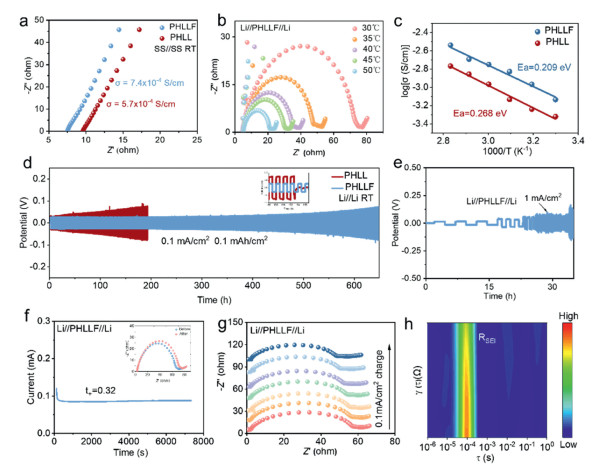
To verify the physical compatibility with metallic lithium, symmetric Li//Li assemblies were constructed. These configurations were then subjected to prolonged galvanostatic plating and stripping to track their dynamic interfacial behavior. The PHLLF electrolyte demonstrates exceptional electrochemical durability, maintaining stable and flat voltage profiles for over 650 h at a current density of 0.1 mA/cm2 (Fig. 2d) and nearly 150 h at 0.25 mA/cm2 (Fig. S4 in Supporting information). In stark contrast, the PHLL baseline cell suffered a premature short circuit after only 190 h at 0.1 mA/cm2 due to uncontrolled lithium dendrite proliferation and poor interfacial intimacy. Furthermore, the critical current density (CCD) of PHLLF was determined to be 1 mA/cm2 (Fig. 2e). This elevated threshold is primarily ascribed to the enriched population of mobile Li+ ions and the minimized interfacial resistance afforded by the FEC-induced, LiF-rich interphase, which effectively homogenizes the Li+ flux at the electrode surface [47]. To precisely determine the Li+ transference number, chronoamperometry and EIS measurements were performed at room temperature (Fig. 2f and Fig. S5 in Supporting information). By fitting the impedance spectra with an equivalent circuit model (Rs)(Rp CPE1)(RctCPE2) (inset of Fig. 2f), PHLLF yields a Li+ of 0.32, significantly higher than that of PHLL (0.26). This improvement reinforces the conclusion that the localized salt enrichment around LLZO particles promotes decoupled Li+ transport. To further elucidate the SEI evolution and its kinetic impact, in-situ EIS was recorded for the Li//PHLLF//Li cell during cycling at 0.1 mA/cm2 (Fig. 2g). The real-time evolution of the impedance spectrum reveals that bulk and interfacial resistances gradually decrease and eventually stabilize. This trend suggests the in-situ formation of a robust, compact and kinetically steady SEI layer that effectively passivates the lithium surface [48,49]. This observation is further corroborated by the distribution of relaxation times (DRT) analysis (Fig. 2h), which deconvolutes the complex interfacial processes and confirms the steady-state nature of Li+ transfer throughout long-term electrochemical cycling.
To evaluate the practical electrochemical efficacy and industrial potential of the PHLLF electrolyte, full cells were architected using Li//LFP and high-voltage Li//NCM811 configurations. As illustrated in Fig. 3a, the Li//PHLLF//LFP cell exhibited a robust rate capability, maintaining exceptional capacity reversibility across an extensive range of current densities from 0.5 C to 10 C. Specifically, the device yielded specific discharge capacities of 168.3, 161.1, 145.6, 134.5, 122.2, 109.5, 96.7, 81.9, 71.3, 61.3, and 52.6 mAh/g at stepwise C-rates up to 10 C. Notably, upon reverting the current density to 0.5 C, a remarkable discharge capacity of 166.4 mAh/g was recovered, manifesting nearly 100% reversibility and structural integrity. In sharp contrast, the PHLL baseline failed to sustain high-rate operation, with its capacity plummeting due to the sluggish Li+ transport kinetics within its non-modified matrix.

The superior electrochemical reversibility of the PHLLF electrolyte was further corroborated by cyclic voltammetry (CV) analysis (Fig. 3b). The Li//PHLLF//LFP cell displayed highly overlapping redox peaks during the initial three cycles, signifying minimal irreversible capacity loss. This outstanding performance is fundamentally attributed to the FEC-induced salt segregation mechanism, which establishes expedited Li+ conduction "highways" at the filler-polymer interfaces [50,51]. Consequently, the charge–discharge plateaus exhibited only negligible polarization and remained remarkably stable even at elevated current densities (Fig. S6 in Supporting information), highlighting the efficiency of the engineered ion-transport networks. Long-term galvanostatic cycling further underscores the durability of the PHLLF electrolyte under demanding conditions. At room temperature, the Li//PHLLF//LFP cell delivered exceptional stability at a high rate of 8 C, maintaining a capacity retention of 92.4% after 640 cycles (Fig. 3c). Even under the more rigorous thermal and kinetic stress of 5 C at 50 ℃, the cell delivered an initial specific discharge capacity of 130.5 mAh/g, achieving 400 stable cycles with 93.3% capacity retention (Fig. 3d). Conversely, the PHLL-based cell suffered from rapid capacity decay at 5 C, reinforcing its inability to accommodate high-power demands. Beyond the LFP system, the high-voltage compatibility of PHLLF was validated in Li//NCM811 full cells. Upon initial evaluation, the assembled batteries yielded a specific discharge capacity of 118.5 mAh/g. More importantly, after undergoing 250 continuous cycles at a rate of 0.5 C, they successfully preserved over 90% of this original capacity (Fig. 3f), demonstrating that the FEC-induced interphase effectively passivates the high-voltage cathode surface and suppresses electrolyte decomposition [52–54]. To further substantiate the role of salt distribution, a high-salt-concentration variant (PHLLF-50%LiTFSI) was synthesized. The corresponding Li//LFP cell delivered an initial specific discharge capacity of 123.5 mAh/g at 2 C, sustaining 300 stable cycles with 95% capacity retention (Fig. 3e), providing definitive evidence that optimized salt partitioning is critical for high-rate performance. Ultimately, the addition of the FEC co-solvent eliminates the physical gaps that typically separate the polymer host from the rigid LLZO particles. Because of this optimized internal architecture, the resulting PHLLF membrane maintains tight physical contact at the electrode boundaries and establishes continuous pathways for accelerated Li+ transport. These combined structural advantages offer a highly viable route toward developing safe, fast-charging solid-state lithium batteries that function reliably across diverse thermal environments.
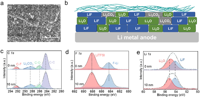
To elucidate the regulatory influence of the PHLLF matrix upon lithium plating dynamics, the microstructural evolution of the active metal subsequent to prolonged cyclic testing was systematically examined. Fig. 4a depicts the interfacial topography of the lithium metal anode retrieved from a cycled Li//PHLLF//Li symmetric cell. The imagery reveals a uniform lithium plating layer characterized by the formation of dense and homogeneous Li microspheres, with an absence of discernible dendrite growth. In stark contrast, SEM analysis of the Li//PHLL//Li baseline cell (Fig. S7 in Supporting information) reveals the proliferation of prominent lithium dendrites across the anode surface. These observations corroborate that the PHLLF electrolyte substantially enhances interfacial stability, facilitating regulated and uniform Li+ deposition. X-ray photoelectron spectroscopy (XPS) depth-profiling was performed to elucidate the chemical constituents and structural evolution of the solid electrolyte interphase (SEI) formed at the Li/PHLLF junction (Fig. 4b). The deconvoluted C 1s spectra (Fig. 4c) exhibits characteristic signals at 284.2, 286, 288.5, and 292.5 eV, assigned to C—C, C—O, Li2CO3, and C-F species, respectively. These components predominantly originate from the decomposition of the LiTFSI salt and the PVDF-HFP matrix. Notably, the relative intensities of these species evolved significantly with increasing sputtering depth, suggesting a well-stratified and chemically resilient interfacial architecture where parasitic side reactions are effectively minimized [55,56]. The F 1s spectra (Fig. 4d) provides additional evidence of the FEC-mediated interfacial modification, displaying characteristic peaks for Li-F (684.4 eV) and LiTFSI (688.1 eV). Compared to the PHLL baseline (Fig. S8 in Supporting information), the PHLLF system demonstrates a markedly elevated proportion of LiF. Although LiF is characterized by a relatively lower bulk ionic conductivity, its high interfacial energy and expansive electrochemical stability window are pivotal for stabilizing the Li surface and inhibiting dendrite nucleation. Unlike the thick, heterogeneous SEI dominated by Li2CO3, which typically triggers rapid polarization and capacity decay, the engineered LiF-rich interphase promotes a more uniform Li+ flux. The XPS results substantiate that FEC introduction significantly augments the LiF content, indicating a more complete dissociation of lithium salts and a regulated decomposition pathway that yields dense, dendrite-free lithium deposition [57,58]. The Li 1s spectra (Fig. 4e) further confirms the inorganic-rich nature of the interphase, with distinct peaks at 54.2 and 55.1 eV assigned to LiF and Li2O, respectively. The progressive enhancement of the LiF signal with sputtering time underscores its prevalence throughout the bulk of the SEI. Collectively, these characterizations demonstrate that the synergistic interaction between LiTFSI and FEC facilitates the in-situ construction of a robust, dense, and LiF-enriched SEI. This optimized interphase effectively mitigates the inherent interfacial instability between the LLZO filler and the lithium anode, providing a chemically compatible and mechanically resilient buffer layer that ensures long-term cycling stability in solid-state batteries.
In summary, the introduction of FEC effectively mitigates the poor interfacial wetting between the SPE and the electrode materials, improving the interfacial contact and simultaneously constructing a stable and fast Li+ transport channel within the electrolyte. The operational capabilities of the complete cell configurations are fundamentally improved by these two intrinsic merits, functioning reliably regardless of whether they are tested at room temperature or high temperatures. Such results clearly highlight the suitability of the PHLLF system for demanding solid-state battery applications.
Qilin Zhang: Writing – original draft, Investigation, Formal analysis, Data curation. Decai Ji: Resources. Wenwei Ding: Software. Qian Ni: Methodology. Wenjuan Zhu: Methodology. Chuyang Li: Formal analysis. Qingqing Zhou: Conceptualization. Bin Wang: Investigation. Yadong Wang: Software. Zhipeng Liu: Supervision. Xiang Han: Writing – review & editing, Supervision, Funding acquisition.
The authors declare that they have no known competing financial interests or personal relationships that could have appeared to influence the work reported in this paper.
This work was financially founded by Basic Research Program of Jiangsu (No. BK20251880) and the Young Elite Scientists Sponsorship Program of the Jiangsu Association for Science and Technology (No. JSTJ-2025–089).
Supplementary material associated with this article can be found, in the online version, at doi:
R. Chen, Q. Li, X. Yu, et al., Chem. Rev. 120 (2020) 6820–6877. doi: 10.1021/acs.chemrev.9b00268
E. Fan, L. Li, Z. Wang, et al., Chem. Rev. 120 (2020) 7020–7063. doi: 10.1021/acs.chemrev.9b00535
J. Pei, X. Bai, P. Xue, et al., Nano Res. Energy 4 (2025) e9120155. doi: 10.26599/nre.2025.9120155
X. Lu, Y. Wang, X. Xu, et al., Adv. Energy Mater. 13 (2023) 2301746. doi: 10.1002/aenm.202301746
N. Xu, Y. Zhao, M. Ni, et al., Angew. Chem. Int. Ed. 63 (2024) e202404400. doi: 10.1002/anie.202404400
L. Xu, S. Tang, Y. Cheng, et al., Joule 2 (2018) 1991–2015. doi: 10.1016/j.joule.2018.07.009
M. Palmer, V.K. Singh, L. Merola, et al., Energy Environ. Sci. 19 (2026) 3283–3299. doi: 10.1039/d5ee07777j
T. Xue, W. Wang, X. Guo, et al., Chin. Chem. Lett. 37 (2026) 112535. doi: 10.1016/j.cclet.2026.112535
X. Han, J. Lu, Q. Zou, et al., Adv. Mater. 37 (2025) 2504419. doi: 10.1002/adma.202504419
B. Sheng, J. Lu, H. Chen, et al., Adv. Funct. Mater. 36 (2026) e14960. doi: 10.1002/adfm.202514960
X. Gao, N. Piao, Y. Yan, et al., Chin. Chem. Lett. 37 (2026) 110591. doi: 10.1016/j.cclet.2024.110591
K. Chen, A. Hu, W. Yang, et al., Adv. Funct. Mater. 36 (2026) e13143. doi: 10.1002/adfm.202513143
R. Yang, D. Ai, S. Fan, et al., Energy Environ. Sci. 18 (2025) 3718–3729. doi: 10.1039/d5ee00368g
R. Lin, Y. He, C. Wang, et al., Nat. Nanotechnol. 17 (2022) 768–776. doi: 10.1038/s41565-022-01148-7
B. Qiu, J. Wen, F. Xu, et al., Angew. Chem. Int. Ed. 65 (2026) e8139928. doi: 10.1002/anie.8139928
X. Han, L. Gu, Z. Sun, et al., Energy Environ. Sci. 16 (2023) 5395–5408. doi: 10.1039/d3ee01696j
G. Zheng, Y. Chen, R. Chen, et al., Chem. Eng. J. 518 (2025) 164616. doi: 10.1016/j.cej.2025.164616
X. Zhang, S. Cheng, C. Fu, et al., Nano-Micro Lett. 17 (2025) 2. doi: 10.1007/s40820-024-01498-y
P. Shi, J. Ma, M. Liu, et al., Nat. Nanotechnol. 18 (2023) 602–610. doi: 10.1038/s41565-023-01341-2
J. Mi, J. Yang, L. Chen, et al., Nature 647 (2025) 86–92. doi: 10.1038/s41586-025-09675-8
J. Wang, Z. Bai, Z. Zhao, et al., Nano Res. Energy 4 (2025) e9120133. doi: 10.26599/nre.2024.9120133
Z. Huang, T. Yang, M. Jiang, et al., Adv. Funct. Mater. 36 (2026) e75619. doi: 10.1002/adfm.75619
G. Huang, R. Chen, Y. Yang, et al., J. Energy Chem. 119 (2026) 155–165. doi: 10.1016/j.jechem.2026.04.026
X. Zhao, Y. Li, C. Wang, et al., Adv. Funct. Mater. 36 (2026) e32132. doi: 10.1002/adfm.202532132
J. Lu, B. Sheng, M. Chen, et al., Energy Storage Mater. 71 (2024) 103570. doi: 10.1016/j.ensm.2024.103570
Q. Zhou, C. Li, B. Wang, et al., J. Colloid Interface Sci. 690 (2025) 137302. doi: 10.1016/j.jcis.2025.137302
R. Li, H. Hua, X. Yang, et al., Energy Environ. Sci. 17 (2024) 5601–5612. doi: 10.1039/d4ee01188k
Y. Yang, H. Zhu, ACS Appl. Energy Mater. 5 (2022) 15086–15092. doi: 10.1021/acsaem.2c02747
J. Biao, B. Han, Y. Cao, et al., Adv. Mater. 35 (2023) 2208951. doi: 10.1002/adma.202208951
A.J. Samson, K. Hofstetter, S. Bag, et al., Energy Environ. Sci. 12 (2019) 2957–2975. doi: 10.1039/c9ee01548e
N. Zhao, W. Khokhar, Z. Bi, et al., Joule 3 (2019) 1190–1199. doi: 10.1016/j.joule.2019.03.019
Q. Zhu, K. Yang, L. Chen, et al., Angew. Chem. Int. Ed. 64 (2025) e202425221. doi: 10.1002/anie.202425221
P. Pan, M. Zhang, Z. Cheng, et al., Energy Storage Mater. 47 (2022) 279–287. doi: 10.1016/j.ensm.2022.02.018
A.M. Nolan, Y. Zhu, X. He, et al., Joule 2 (2018) 2016–2046. doi: 10.1016/j.joule.2018.08.017
Y. Huang, G. Rui, Q. Li, et al., Nat. Commun. 12 (2021) 675. doi: 10.1111/jfd.13329
K. Cheng, S. Tu, B. Zhang, et al., Energy Environ. Sci. 17 (2024) 2631–2641. doi: 10.1039/d4ee00407h
L. Cheng, Y. Wang, J. Yang, et al., Adv. Funct. Mater. 33 (2023) 2212349. doi: 10.1002/adfm.202212349
L. Ruan, X. Yao, Y. Chang, et al., Polymers 10 (2018) 228. doi: 10.3390/polym10030228
Q. Lv, C. Li, Y. Liu, et al., ACS Nano 18 (2024) 23253–23264. doi: 10.1021/acsnano.4c06057
Y. Jing, S. Liu, C. Li, et al., Chem. Eng. J. 511 (2025) 162149. doi: 10.1016/j.cej.2025.162149
Z. He, E. Dong, C. Li, et al., J. Energy Chem. 116 (2026) 504–513. doi: 10.1016/j.jechem.2026.01.017
C. Li, Y. Jing, J. Zhu, et al., Adv. Funct. Mater. 36 (2026) e22002. doi: 10.1002/adfm.202522002
P. Prakash, B. Fall, J. Aguirre, et al., Nat. Mater. 22 (2023) 627–635. doi: 10.1038/s41563-023-01508-1
W. Huang, S. Wang, X. Zhang, et al., Adv. Mater. 35 (2023) 2310147. doi: 10.1002/adma.202310147
C. Zhang, Z. Jiang, X. Yang, et al., Chem. Eng. J. 523 (2025) 168521. doi: 10.1016/j.cej.2025.168521
X. An, Y. Liu, K. Yang, et al., Adv. Mater. 36 (2024) 2311195. doi: 10.1002/adma.202311195
C.X. Zhao, Z. Wang, D. Jacobson, et al., Science 390 (2025) 745–750. doi: 10.1126/science.adv1739
L. Zhang, Y. Dai, C. Li, et al., Energy Storage Mater. 69 (2024) 103378. doi: 10.1016/j.ensm.2024.103378
M. Liu, A. Song, X. Zhang, et al., Nano Energy 136 (2025) 110749. doi: 10.1016/j.nanoen.2025.110749
D. Zhang, Y. Liu, D. Li, et al., Energy Environ. Sci. 18 (2025) 227–235. doi: 10.1039/d4ee04078c
N. Wu, P.H. Chien, Y. Qian, et al., Angew. Chem. Int. Ed. 59 (2020) 4131–4137. doi: 10.1002/anie.201914478
J. Lu, B. Sheng, Q. Fang, et al., eScience 6 (2026) 100462. doi: 10.1016/j.esci.2025.100462
H. Huo, Y. Chen, R. Li, et al., Energy Environ. Sci. 13 (2020) 127–134. doi: 10.1039/c9ee01903k
K. Liu, H. Cheng, Z. Wang, et al., Adv. Energy Mater. 14 (2024) 2303940. doi: 10.1002/aenm.202303940
H. Zeng, K. Yu, J. Li, et al., ACS Nano 18 (2024) 1969–1981. doi: 10.1021/acsnano.3c07038
X. Liu, S. Li, C. Yuan, et al., Nature 646 (2025) 102–107. doi: 10.1038/s41586-025-09498-7
P.G. Kitz, M.J. Lacey, P. Novák, et al., J. Power Sources 477 (2020) 228567. doi: 10.1016/j.jpowsour.2020.228567
P. Jiang, J. Cao, B. Wei, et al., Energy Storage Mater. 48 (2022) 145–154. doi: 10.1016/j.ensm.2022.03.017

Figure 1 Comprehensive morphological, structural, and physicochemical evaluations of the composite solid polymer electrolytes. (a) Topographical SEM micrograph of the PHLLF membrane surface. (b) Corresponding EDS spatial distribution maps for La, F, Zr, and O elements within the PHLLF matrix. (c) Cross-sectional SEM visualization of the PHLLF electrolyte. (d) AFM topographical profile illustrating the surface features of PHLLF. Comparative structural analyses via (e) XRD, (f) FTIR absorption profiles, and (g) Raman scattering spectra for the PHLL baseline and modified PHLLF membranes. Comparative physical property assessments displaying (h) tensile stress–strain behaviors and (i) TGA thermograms of the PHLL and PHLLF electrolytes.

Figure 2 Comprehensive electrochemical evaluations and interfacial stability assessments of the composite solid polymer electrolytes. (a) EIS profiles for symmetric SS//SS configurations utilizing the PHLL baseline and modified PHLLF membranes. (b) Temperature-dependent Nyquist plots for the Li//PHLLF//Li symmetric assemblies. (c) Arrhenius plots of ionic conductivity. (d) Long-term galvanostatic cycling voltage traces of the Li//PHLLF//Li symmetric cell evaluated at 0.1 mA/cm2 with a fixed areal capacity of 0.1 mAh/cm2 under ambient conditions. (e) CCD threshold evaluation for the PHLLF system. (f) Chronoamperometry (current–time) responses for the lithium symmetric configurations employing the PHLLF electrolyte. Insets display the utilized equivalent circuit model alongside the AC impedance spectra recorded prior to and post DC polarization. (g) In-situ temporal evolution of the impedance profiles during the continuous charging process of the PHLLF cell. (h) Corresponding DRT deconvolutions extracted from the initial charge cycle spectra.

Figure 3 Electrochemical performance characterizations of the assembled solid-state full cells employing LFP and NCM811 cathodes. (a) Rate capability profiles recorded across a wide range of C-rates from 0.5 C to 10 C under ambient conditions. (b) CV traces for the first three continuous cycles of the Li//PHLLF//LFP configuration, scanned at 0.2 mV/s at room temperature. (c) Comparative prolonged galvanostatic cycling stability of the full cells employing the PHLLF and baseline PHLL electrolytes. (d) High-temperature cycling durability of the Li//PHLLF//LFP assembly evaluated at a rigorous rate of 5 C at 50 ℃. (e) Galvanostatic cycling behavior of the Li//LFP system incorporating the concentrated salt variant PHLLF-50% LiTFSI tested at 2 C and room temperature. (f) Capacity retention trace of the high-voltage Li//PHLLF//NCM811 cell operated at 0.5 C under ambient conditions.

Figure 4 Morphological evaluations and interfacial chemistry of the SEI formulated on the lithium metal anode. (a) Post-cycling SEM micrograph detailing the surface topography of the lithium metal electrode. (b) Mechanistic illustration depicting the structural architecture of the SEI layer engineered by the PHLLF electrolyte matrix. (c–e) Depth-dependent XPS profiles elucidating the chemical constituents of the SEI on the lithium anode.

 扫一扫看文章


扫一扫关注我们
 DownLoad:

 下载:
 下载: