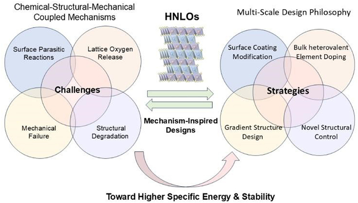
Figure 1.
Venn diagram summarizing the multi-scale coupled failure mechanisms and stabilization strategies of current high-energy HNLOs cathodes.

Multi-scale coupled failure mechanisms and stabilization strategies of high-nickel cathodes for next-generation high-energy lithium-ion batteries
Jun Wang , Ting Liu , Juping Xu , Guanjie Zhang , Yan Zhao , Huaican Chen , Jinxiang Fan , Sijie Guo , Sidong Zhang , Wen Yin , An-Min Cao


Lithium-ion batteries (LIBs), endowed with high energy density, long cycle life, and decreasing cost advantages, have evolved from the dominant power source for consumer electronics to strategically emerging fields such as electric transportation, large-scale energy storage, and aerospace [1–3]. They have become a critical technological carrier supporting the global energy structure transformation and the achievement of “dual carbon” goals [4]. It is predicted that the global demand for power batteries will surge from 492 GWh in 2021 to 2–3.5 TWh in 2030, which imposes unprecedentedly stringent requirements on the energy density, safety, and manufacturing cost of LIBs [5]. Among the components of LIBs, cathode materials not only serve as the primary source of Li+ but also directly determine the upper limit of battery energy density and the overall cost composition, thus becoming the core breakthrough to overcome the performance bottleneck of next-generation high-energy-density LIBs [6,7]. To meet the ever-increasing performance demands, researchers have been dedicated to expanding the operating voltage window of cathode materials and designing new material systems with higher reversible capacity [8]. In this context, high-nickel layered oxides (HNLOs, LiNixM1-xO2, x ≥ 0.6, M = Co, Mn, Al, etc.) stand out. They offer high specific capacity (commercial LiNi0.8Co0.1Mn0.1O2 delivers ~220 mAh/g at 4.5 V), a suitable voltage platform, and relatively low material cost. Hence, HNLOs are regarded as one of the most promising next-generation high-energy-density cathodes for near-term industrialization, attracting extensive attention from both academia and industry [7,9].
The electrochemical behavior of HNLOs cathodes is intrinsically governed by a profound structure-property relationship rooted in their electronic structure and crystal chemistry [10]. In the typical LiNixCoyMn1-x-yO2 (NCM) ternary material system, each transition metal (TM) ion plays a distinct functional role based on differences in their energy level structure, redox activity, and crystal field stabilization energy [10,11]. Specifically, since the energy level of Mn3+/4+ is higher than that of Ni2+/3+, Mn tends to exist in the stable Mn4+ form during synthesis, stabilizing Ni as electrochemically active Ni2+ and acting as a lattice stabilizer, while itself barely participating in redox reactions. In contrast, the Co3+/4+ energy level overlaps significantly with the O 2p orbital. This overlap enhances electronic conductivity and rate performance. However, it also easily induces irreversible lattice oxygen release in the highly delithiated state [12]. From the perspective of structural stability, due to its low octahedral site preference energy, Mn tends to migrate from the TM layer to the lithium layer during charge-discharge processes, triggering irreversible transformation of the layered structure to spinel or even rock-salt phases, leading to voltage decay and capacity loss. In contrast, Co exhibits better structural stability due to its high octahedral site preference energy, which can effectively inhibit cation mixing. The structural stabilization energy of Ni3+ is between that of Mn and Co, endowing it with both high capacity contribution and acceptable structural stability. Based on these characteristics, NCM materials have followed a clear evolutionary path of “high nickel and low cobalt”. The progression goes from early low-nickel LiNi1/3Co1/3Mn1/3O2, to medium-nickel LiNi0.5Co0.2Mn0.3O2 and LiNi0.6Co0.2Mn0.2O2, and finally to today’s high-nickel materials with Ni content exceeding 80 mol% or even 90 mol% [13,14]. This evolution continuously increases capacity but also poses severe challenges to the chemical and structural stability of the materials [15].
Although the increase in nickel content significantly enhances the discharge capacity of the material, the accompanying instability issues have become the key bottleneck restricting its commercial application [16]. From the perspective of chemical stability, the main challenge of high-nickel materials stems from the strong oxidizing property of Ni3+/Ni4+ [17]. In the highly delithiated state, strongly oxidizing Ni4+ tends to undergo violent side reactions with the organic electrolyte. These reactions cause oxidative decomposition of the electrolyte, excessive growth of the cathode-electrolyte interphase (CEI), and a sharp increase in interfacial impedance. At the same time, irreversible lattice oxygen evolution under high voltage further aggravates surface and interface chemical instability. This triggers a phase transition of the surface structure from an ordered layered phase to an inert rock-salt phase (NiO-type structure). This surface reconstruction layer severely hinders Li+ diffusion from the electrolyte into the bulk, leading to deteriorated kinetic performance and rapid capacity decay [18]. More critically, this problem is not limited to electrochemical cycling [19]. High-nickel materials also show significant instability during high-temperature synthesis, air storage, and even electrode slurry preparation. Residual lithium on the material surface (in the form of LiOH, Li2CO3, etc.) not only reduces reversible capacity but also causes gelation of the electrode slurry during preparation, worsening the coating process. Moreover, these surface residues decompose to produce gas during battery charge–discharge, leading to safety issues such as battery swelling [20,21]. Recent studies have shown that single-crystal high-nickel cathodes can induce an unconventional O1* phase transition during air exposure, which is different from the conventional formation mechanism of surface Li2CO3. Instead, it directly causes lattice mismatch, dislocation multiplication, and local strain concentration. During subsequent cycling, these distorted regions develop into intragranular cracks, providing fast channels for electrolyte penetration and further rock-salt phase transition, ultimately leading to catastrophic capacity decay of the battery [22].
It is worth noting that dynamic structural degradation under electrochemical operating conditions is another major challenge for high-nickel cathodes. The degree of degradation closely depends on the charge-discharge cutoff voltage, cycle number, and rate conditions [23,24]. When the charging voltage exceeds 4.5 V, deeper Li+ extraction further increases the oxidation state of Ni3+/4+ and activates the redox activity of oxygen anions in the lattice. This leads to irreversible release of lattice oxygen, mainly as singlet oxygen (1O2) or molecular oxygen (O2) [25]. This process not only causes accumulation of oxygen vacancies in the bulk but also triggers a cascade of problems: Interface deterioration, structural phase transformation, and mechanical failure [26]. These problems gradually worsen during battery cycling, ultimately significantly reducing the stability and safety of high-specific-energy LIBs, and posing severe challenges to their large–scale application [27]. Despite extensive efforts in materials physics, synthetic chemistry, and interface engineering, the inherent trade-off between “high specific energy” and “high stability” in high-nickel materials remains. There is an urgent need to develop more precise regulation strategies based on a deeper understanding of chemical-structural-mechanical coupled failure mechanisms.
Based on the above analysis, this review aims to systematically summarize and discuss structural stability regulation strategies and recent research progress for HNLOs cathode materials, from the perspective of chemical-structural-mechanical multi-scale coupled failure (Fig. 1). This review first analyzes the key failure mechanisms that limit the stability of high-nickel materials. These include surface and interface side reactions, irreversible lattice oxygen release, cation mixing and structural degradation, and mechanical failure. On this basis, we systematically review recent refined structural regulation methods, such as surface coating, bulk heterovalent element doping, gradient design, and novel structural control methods. We clarify how these methods regulate the chemical composition, crystal structure, multi-scale morphology, and interface chemical properties of high-nickel cathodes. In particular, we discuss how these strategies achieve uniform and reversible Li+ extraction/insertion and inhibit structural degradation. Finally, combining current research frontiers with industrial application needs, we provide a perspective on future challenges and possible development directions for HNLOs cathode materials toward high energy density, long cycle life, and high safety. Our goal is to offer a theoretical basis and practical guidance for designing cathode materials for next–generation high-specific-energy LIBs.
The cycle life and safety concerns of high-nickel cathode materials under high operating voltages have emerged as a primary bottleneck impeding their commercial viability [15]. These performance degradation phenomena are intrinsically linked to the surface chemical properties and structural stability of the material [16]. Importantly, the underlying degradation mechanisms transcend traditional, single-dimensional understandings and instead exhibit highly coupled multi-scale characteristics from a chemical-structural-mechanical perspective, encompassing interfacial parasitic side reactions, irreversible lattice oxygen release, cation mixing-induced phase transformation, and chemo-mechanical failure.
Typically, during charging, HNLOs experience an increase in the Ni valence state. The highly reactive Ni4+ ions trigger severe parasitic side reactions at the cathode/electrolyte interface, leading to excessive growth of the CEI and a sharp rise in interfacial impedance. Concurrently, the progressive increase in charging voltage triggers oxidation and loss of lattice oxygen from the cathode [25]. The irreversible release of lattice oxygen not only results in the accumulation of surface oxygen vacancies but also induces the migration of TM ions and cation mixing. This process drives an irreversible phase transformation from an ordered layered structure to an electrochemically inert rock-salt phase. The formation of such a degraded rock-salt phase within the cathode further leads to inhomogeneous Li+ (de)intercalation. In other words, repeated Li+ extraction/insertion processes generate more pronounced anisotropic volume changes within the crystal lattice, initiating microcracks in the secondary particles. These cracks compromise the electrical integrity of the particles and provide rapid infiltration pathways for the electrolyte, thereby exacerbating interfacial side reactions and structural degradation along internal grain boundaries [28]. The synergistic interplay of these mechanisms encompasses a multi-dimensional failure cascade in HNLOs—spanning chemical reactivity, crystallographic phase transformation, interfacial evolution, particle mechanical integrity, and electrode uniformity—which significantly deteriorates the electrode’s kinetic performance and cycling stability, posing a major obstacle to the practical application of high-energy-density cathode materials.
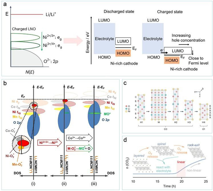
Detrimental side reactions between the electrolyte and the highly reactive surface of deeply delithiated high-nickel cathodes are a primary cause of capacity fading [29,30]. This phenomenon becomes increasingly pronounced with higher Ni content and deeper delithiation states [31]. Under high-voltage conditions, electrolyte decomposition is primarily initiated by the oxidation of carbonate solvents on the cathode surface, proceeding via both electrochemical and chemical oxidation mechanisms [32]. Chemical oxidation, which is prevalent across a wide electrode potential range, is identified as the dominant pathway for electrolyte decomposition [33]. Electrochemical oxidation is a Faradaic process governed by the oxidation potential and reaction kinetics at the electrode/electrolyte interface. It typically occurs at potentials above 4.8 V (vs. Li/Li+) and fundamentally involves electron transfer when the highest occupied molecular orbital (HOMO) energy level of the electrolyte is higher than the lowest unoccupied molecular orbital (LUMO) energy level of the cathode [34]. As demonstrated by Takahashi et al. [35], during the charging of high-nickel layered cathodes, the antibonding hybridized orbital derived from TM 3d and oxygen 2p states (corresponding to the LUMO level) progressively approaches the HOMO level of the electrolyte. This convergence facilitates electrolyte oxidation driven by the increasing voltage (Fig. 2a).
Chemical oxidation, in contrast, is directly correlated with the surface reactivity of the cathode in its charged state [36]. As the state of charge (SOC) increases, the predominantly ionic TM2+/3+-O bonds in the high-nickel cathode gradually transform into more covalent TM4+-O bonds. This transition promotes electron transfer from the O 2p state and accelerates the reduction of TM4+ [17]. The enhanced covalency of transition metal-oxygen (TM-O) bonds thermodynamically drives the dehydrogenation of carbonate solvents at the surface, a process intimately linked to the high nucleophilicity of surface oxygen species. The protonated species generated from dehydrogenation react with the LiPF6 salt, forming LiMxFyOz compounds [37]. The extent of lithium salt degradation intensifies with higher Ni content and elevated SOC [38], originating from the lowering of the Fermi level into the O 2p band at high SOC for high-nickel compositions, which significantly activates surface oxygen species [39]. The oxidative decomposition of the electrolyte results in the formation of a solid CEI layer on the cathode surface. Higher Ni content and deeper delithiation lead to greater surface reactivity, accelerating electrolyte decomposition and consequently forming a thicker CEI layer [40]. Such a thick CEI layer significantly impedes Li+ diffusion kinetics and increases interfacial impedance, ultimately inducing rapid capacity decline in LIBs [41].
Lattice oxygen release is a central factor triggering structural degradation in high-nickel cathode materials [27,42]. Under overcharged states, the lattice stability of deeply delithiated layered cathodes diminishes sharply, prompting the release of highly reactive oxygen species such as O2-, O-, O22-, and O2 from the surface [43,44]. The underlying cause is a fundamental change in the bonding characteristics of TM-O bonds during delithiation. As delithiation progresses, electron removal drives the transformation of ionic TM-O bonds towards covalent bonding, facilitating electron transfer from the O 2p state concomitant with TM4+ reduction. This thermodynamically favors electron transfer between O2- and TM4+, ultimately triggering oxygen evolution. To elucidate the structure-property relationship governing the chemical instability and oxygen release in HNLOs cathodes, a valence band structure model has been proposed (Fig. 2b) [45]. In this model, the highest energy band of layered cathodes comprises antibonding Ni eg states, bonding Ni/Co/Mn t2g states, and O 2p states. As the delithiation degree deepens (schematically illustrated from (ⅰ) to (ⅲ) in Fig. 2b), electron removal shifts the energy of these states towards the Fermi level, causing the TM t2g states to overlap with the O 2p band. This overlap facilitates the formation of TM-O2* intermediates, providing the kinetic driving force for oxygen release.
The evolved highly reactive oxygen species can initiate electrolyte oxidation and concurrently exacerbate both chemical and mechanical degradation of the cathode material, leading to capacity fading through multiple intertwined pathways [46]. Notably, oxygen release behavior is closely linked to the Ni content, delithiation state, and operating potential of the cathode. Under overcharge conditions, reactions between reactive oxygen and the flammable electrolyte can easily trigger thermal runaway and release hazardous gases [47], posing a serious threat to battery operational stability and safety [16,48].
As summarized above, high potentials drive increased surface chemical reactivity of HNLOs cathodes, triggering interfacial side reactions with the electrolyte and inducing lattice oxygen release along with oxygen vacancy formation. These processes, in turn, exacerbate Li/Ni mixing and irreversible structural phase transformations, severely compromising material structural stability [49]. At high SOC, the enhanced covalency of Ni-O bonds promotes electron transfer from lattice oxygen to Ni4+, facilitating the reduction of Ni4+ to Ni2+. Due to the similar ionic radii of Ni2+ and Li+, Ni2+ ions tends to migrate to Li layer sites, inducing a progressive transformation of the initial layered structure to a disordered spinel phase and ultimately to a rock-salt phase [50,51]. This electrochemically inert rock-salt impurity phase significantly impedes Li+ diffusion [52]. The above structural degradation process is intricately linked to the delithiation state, Ni content, and reactivity with electrolyte solvents, among which the delithiation state is the core determining factor [53]. Taking the LiNi0.5Co0.2Mn0.3O2 electrodes as the research object, it was found that its surface structural degradation is highly dependent on the cut-off voltage. At 4.5 V, the surface layered structure transforms into a mixture of spinel and rock-salt phases. At 4.8 V, due to substantial release of surface lattice oxygen, the rock-salt phase becomes dominant (Figs. 2c and d) [54–56]. Crucially, this structural transformation can initiate as early as the first charge cycle. During extended cycling, structural degradation in HNLOs cathodes exhibits a progressive “surface-to-bulk” propagation characteristic with distinct anisotropy. The degraded surface layer is thicker at the termini of Li+ diffusion pathways, indicating that the Li+ (de)intercalation process itself accelerates surface structural deterioration [57]. Furthermore, electrolyte attack can lead to TM ion dissolution. Concomitantly, Ni ions from the bulk continuously migrate towards the surface and may dissolve into the electrolyte, driving the surface degradation layer deeper into the particle interior and significantly diminishing the reversible capacity and electrochemical cycling stability of the cathode [58,59].
Mechanical stability is a critical determinant of the structural integrity and electrochemical performance of HNLOs cathodes, subjected to repeated lattice contraction and expansion during long-term cycling, inevitably experience inhomogeneous stress distribution (Fig. 3a), culminating in mechanical failure [60]. During cycling, the cathode undergoes multiple phase transitions, from the initial H1 phase to the M, H2, and H3 phases upon charging, a process that reverses during discharge [61]. Among these, the H2-H3 phase transition is particularly detrimental to the structural stability of layered electrodes due to the accompanying abrupt lattice contraction, which acts as a primary factor for microcrack nucleation [62,63]. Studies have demonstrated the impact of cut-off voltage on the mechanical stability and phase transitions of LiNiO2 [64]. It was observed that LiNiO2 electrode particles charged to 4.1 V remained intact, whereas those charged to 4.2 V and 4.3 V developed significant cracks. Electrodes charged to 4.1 V underwent the H1-M-H2 phase transitions but not the deleterious H2-H3 transition occurring near 4.15 V. These results confirm the predominant role of the H2-H3 phase transition in microcrack formation (Fig. 3b).
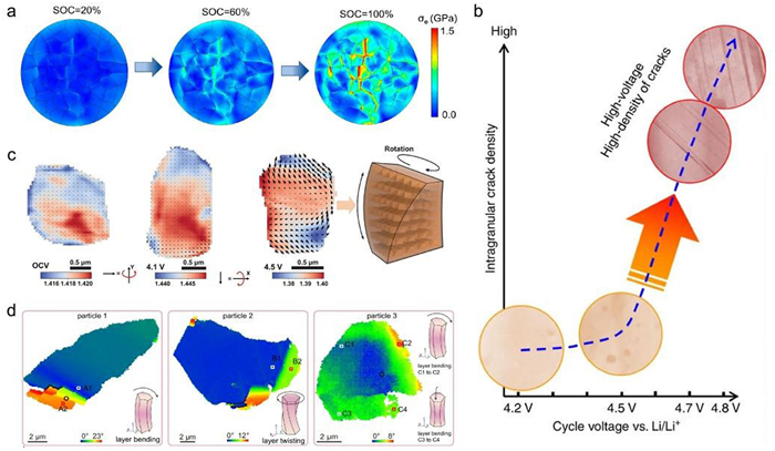
At a deeper level, the spatial heterogeneity in Li+ concentration leads to differences in lattice volume inside the primary particles, causing local stress and strain concentration, which in turn induces dislocations, tearing of TM layers and intragranular cracks along the (003) crystal plane [65,66]. Recent research has further elucidated electrochemical-mechanical degradation mechanisms such as lattice rotation and lattice plane bending. For instance, Amine and colleagues, using a polycrystalline rocking curve technique, discovered that inhomogeneous electrochemical reactions during delithiation induce lattice stress and rotation in single-crystal HNLOs cathodes [67]. Notably, this lattice rotation exhibits significant irreversibility, accumulating upon cycling and ultimately leading to structural degradation and interfacial failure. Their study proposed lattice rotation as a sensitive indicator for evaluating material structural stability (Fig. 3c). Building upon this, Li et al. systematically visualized the spatial distribution of lattice strain within LiNi0.92Co0.06Mn0.02O2 particles using electron backscatter diffraction imaging and grain reference orientation deviation (GROD) angle maps [68]. Combined with pole figure analysis, they identified two distinct distortion modes: Layer bending and layer twisting. Statistical analysis revealed that the accumulation of layer bending is the primary kinetic mechanism responsible for capacity loss (Fig. 3d), deepening the understanding of electrochemical-mechanical failure mechanisms in layered cathode materials. These findings offer new perspectives on structural regulation for the development of next-generation, high-stability Ni-rich cathode materials.
To address the critical challenges plaguing high–nickel layered oxide cathodes discussed above, diverse modification strategies have been extensively developed. Given the multi–dimensional nature of the failure mechanisms in HNLOs cathodes, existing research approaches have largely focused on novel structural designs targeting the cathode surface, bulk, surface–to–bulk gradient architectures, as well as particle morphology, crystallographic facet, and defect engineering. These methods include surface coating modification, bulk elemental doping, gradient structure design, and novel structural control. Considering the increased chemical reactivity of the HNLOs surface during charging—which makes it highly susceptible to parasitic side reactions with organic electrolytes—researchers have developed functional surface coating strategies to protect the cathode surface, mitigate interfacial side reactions, and stabilize the surface [69]. However, surface modification alone cannot alleviate irreversible phase transformation or structural degradation within the cathode bulk. Consequently, bulk heterovalent element doping strategies have been developed to stabilize the bulk lattice and enhance ion transport capability by incorporating various functional elements into different sites within the layered lattice, thereby suppressing irreversible phase transformation and structural degradation [70]. Nevertheless, bulk doping strategies cannot effectively stabilize the cathode surface structure. Therefore, gradient structure designs from the surface to the bulk have been developed to achieve simultaneous stabilization of both surface and bulk while avoiding the loss of protective performance due to coating delamination [71]. However, gradient structure designs often rely on overly stringent synthesis control, complex procedures, and high processing costs, making large–scale application challenging. In response, recent years have seen the development of novel structural control methods that balance structural stabilization with operational simplicity. These methods enable direct regulation of key structural features—such as overall particle morphology, crystallographic facets, and defects—through streamlined synthesis processes, tackling the failure issues that limit cathode stability from multiple dimensions including particles, crystal phases, and local defects. Despite significant progress, these current methods still fall short of achieving comprehensive multi–dimensional stabilization of HNLOs cathodes with higher nickel content, and further optimization is needed in terms of process simplicity and cost control.
In LIBs, the chemical reactivity of the cathode material exerts a profound influence on both the nature and severity of parasitic side reactions at the cathode-electrolyte interface, and critically impacts the electrochemical reaction kinetics, including Li+ diffusion and charge transfer. Consequently, tailoring the surface chemical properties of high-nickel cathodes represents an effective strategy to enhance their cycling and thermal stability [40,72]. Surface coating is widely recognized as one of the most efficacious methods for improving the chemical stability of cathode materials [73,74]. The primary function of a coating is to provide a physical barrier between the active cathode surface and the electrolyte, thereby preventing detrimental interfacial side reactions [75]. To ensure effectiveness, the coating layer must exhibit robust chemical and electrochemical stability, resisting electrolyte attack under high cut-off voltage [76]. In contemporary research, electrochemically inert materials such as metal oxides, fluorides, and phosphates are commonly employed as coating species [77]. Beyond serving as a physical barrier, these oxide coatings can also react with HF present in the electrolyte, forming corrosion-resistant fluorides that further suppress surface structural degradation [78]. However, the inert coating layer is unfavorable for interfacial ion transport, leading to reversible capacity loss and reduced rate performance of the battery.
To overcome the problem of slow electrochemical kinetics of the inert layer during cathode cycling, researchers have adopted fast ion conductor species to coat the cathode. This type of coating material exhibits high ion transport rate driven by the electrochemical potential gradient, and its unique crystal structure has large transport channels for Li+ diffusion, while concurrently improving the stability of the cathode to a certain extent [79]. Yan et al. employed vapor-phase atomic layer deposition (ALD) to coat amorphous Li3PO4 onto secondary particles of a polycrystalline HNLOs cathode [80]. Following annealing at 600 ℃, the amorphous Li3PO4 layer melted and infiltrated the grain boundaries between primary particles (Fig. 4a). On one hand, this Li3PO4 electrolyte layer significantly bolstered both structural and interfacial stability, enabling long-term cycling stability of capacity and voltage. On the other hand, the Li3PO4 layer at the surface and grain boundaries provided pathways for rapid Li+ transport while preventing liquid electrolyte penetration into grain boundaries. This improvement mitigated multiple detrimental factors, including solid-liquid interfacial reactions, irreversible layered-to-spinel phase transformation, and intergranular cracking. Nevertheless, the limited electronic conductivity of solid electrolytes remains a constraint for enhancing rate capability. To improve interfacial structural stability without sacrificing electronic conductivity, conductive polymers such as poly(3,4-ethylenedioxythiophene) (PEDOT) have been utilized as coatings to alleviate parasitic interfacial reactions and intergranular microcracks (Fig. 4b), while simultaneously facilitating rapid transport of both Li+ and electrons [81]. During electrochemical cycling of coated cathodes, irreversible phase transformations and microcracks induced by repeated Li+ (de)intercalation can cause delamination of the coating layer from the cathode surface, compromising its protective function. Therefore, to strengthen interfacial adhesion between the coating and the cathode, Cho et al. employed CoxB as a coating material. The high reactivity between CoxB and lattice oxygen enhanced the wettability of the cathode particle surface by CoxB, ensuring uniform coating coverage and robust adhesion (Fig. 4c). This CoxB coating stabilized surface/interfacial oxygen activity, thereby enhancing both mechanical stability and electrochemical cycling stability of the cathode [82].
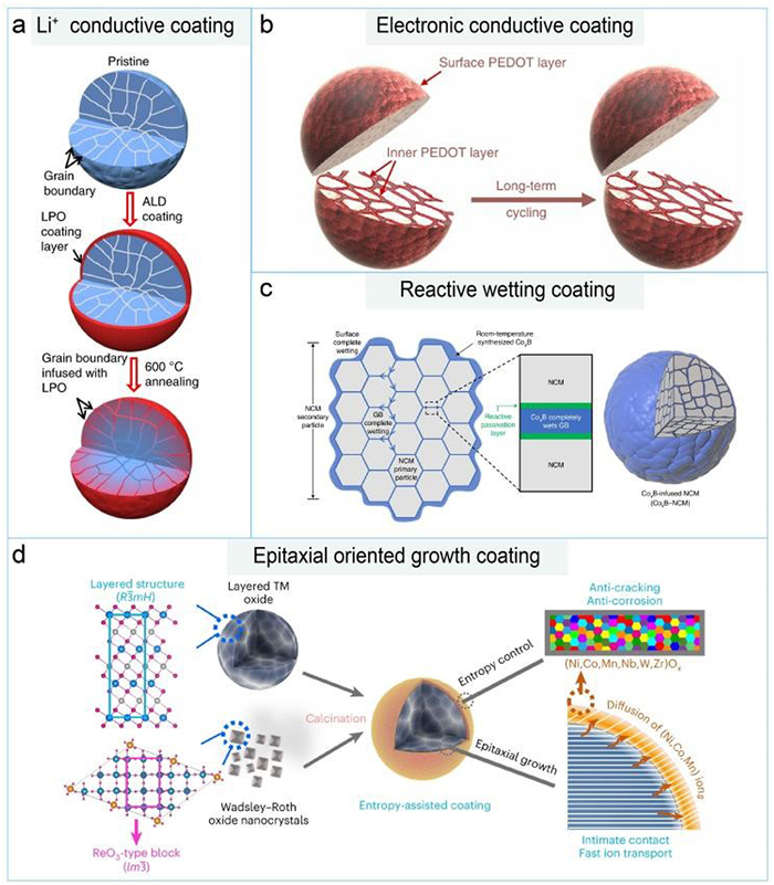
In recent years, with advancing understanding of cathode failure mechanisms, novel coating strategies have emerged to stabilize cathodes, particularly evident in the design of multifunctional composite coatings. For instance, coatings can react with residual lithium compounds on the cathode surface, eliminating excess lithium residues while simultaneously generating a Li+-conductive layer, thereby improving cycling performance [83]. Sun et al. employed a cobalt-dissolved aqueous solution washing treatment combined with a fluorination coating process to concurrently remove lithium residues and form a cobalt-rich and LiF-rich protective layer on the cathode surface. This approach mitigated the detrimental effects of residual lithium compounds, effectively suppressed surface structural degradation and gas release, and enhanced the cycling stability of HNLOs cathodes [73]. To address the problem of oxygen release under high voltage, Xie et al., inspired by the strong chelating effect of phytic acid (PN) on TM, utilized PN as a cathode additive to coordinate with Ni [84]. This coordination weakened the charge compensation from TM 3d to O 2p on the LiNi0.8Co0.1Mn0.1O2 (NCM811) cathode surface. The chelation successfully stabilized lattice oxygen and inhibited the release of reactive oxygen species (O), reducing O-related crossover reactions and improving battery safety. Amine et al. leveraged the characteristic of Wadsley-Roth phase crystals (e.g., Nb12WO33) to undergo oriented attachment growth on HNLOs cathodes, forming an epitaxial entropy-assisted oxide coating on the surface with excellent coverage (Fig. 4d). This significantly enhanced the chemo-mechanical stability of the cathode surface, effectively boosting the cycling performance of ultra-high Ni cathodes under extreme operating conditions [85]. Despite the numerous advantages of multifunctional composite coatings, their design and fabrication present a series of challenges. For example, the selection and proportioning of coating materials necessitate in-depth research and optimization to achieve optimal performance. Furthermore, the coating preparation process must be rigorously controlled to ensure uniformity. Therefore, the development of multifunctional coatings requires interdisciplinary collaboration and systematic investigation.
Given that surface coating modification strategies cannot effectively stabilize the bulk lattice structure of HNLOs, bulk heterovalent element doping strategies have been developed to target the structural stability of the cathode bulk, aiming to suppress irreversible lattice phase transformation and structural degradation during repeated Li+ (de)intercalation. This approach involves integrating small quantities of additional elements into the material’s lattice (typically less than 5% of the host material), modifying its bulk crystal structure, enhancing bulk structural stability, and improving ion diffusion pathways, thereby boosting electrochemical performance [86]. Based on the charge characteristics of the dopants, bulk heterovalent element doping strategies can be categorized into three main systems: Cation doping, anion doping, and cation–anion co–doping. Their specific stabilization mechanisms for HNLOs cathodes are discussed below.
Cation doping typically involves substituting a fraction of the host TM ions (e.g., Ni, Co, Mn) in the crystal lattice with cationic species such as Zn2+, B3+, In3+, Ga3+, Al3+, Ti4+, Zr4+, Nb5+, Ta5+, W6+, and Mo6+ [86,87]. This modification strategy enhances the structural stability of the cathode material by altering lattice parameters, crystal structure, and chemical interactions. The mechanisms of cation doping at TM sites can be summarized as follows: (1) Suppression of abrupt lattice parameter changes: Cations occupying TM sites can effectively mitigate drastic changes in lattice parameters during phase transitions, reducing lattice strain and accumulated stress. (2) Enhanced ion diffusion: Cation doping optimizes the electronic structure and charge transfer characteristics of the cathode material, promoting Li+ migration within the crystal structure and improving Li+ diffusion kinetics. Additionally, certain cations with larger ionic radii (e.g., Na+, Mg2+, and Sc3+) can partially substitute for Li+ in the lithium layers [88,89]. These cations act as “pillars” within the layered structure, effectively preventing excessive deformation of the layers and thereby mitigating capacity fade. These “pillar ions” can also inhibit the migration of TM cations like Ni2+ into the lithium layers, reducing Li+/Ni2+ cation mixing and slowing structural degradation. To more fully leverage the structural stability and ionic transport enhancements enabled by such cation doping, recent research has increasingly focused on the co-incorporation of multiple functionally distinct cations into the lattice to achieve superior cycle life. Xin et al. exploited the differential solubility of high- and low-valence elements in NCM cathodes by co-introducing high-valence Ti, Nb, Mo and low-valence Mg (Fig. 5a) [90]. The high-valence species tend to segregate at the surface, where they form strong bonds with oxygen, thereby stabilizing the local crystal structure, whereas Mg is more uniformly incorporated into the bulk lattice, effectively mitigating Li/Ni cation mixing. Leveraging the pronounced advantage of high-valence elements in stabilizing lattice oxygen, a Na-Ti co-doping strategy has been employed to enrich Ti within a 9 nm surface layer (Fig. 5b), substantially enhancing structural integrity and suppressing parasitic cathode-electrolyte reactions [91]. This enables stable long-term cycling even at a high cut-off voltage of 4.8 V. In recent years, various cation–based high–entropy doping strategies have been adopted to stabilize HNLOs cathodes [92,93]. For example, up to nine different cations (Ni, Co, Mn, Nb, Mg, Al, Ti, Zr, and Ag) can co–occupy the TM sites, each playing a distinct role [92]. Among them, Al, Mg, Zr, and Ag serve to reinforce structural integrity during Li+ deintercalation, whereas Nb and Ti are intended to elevate the average operating voltage. Collectively, such high–entropy doping strengthens the TM-O interaction, mitigates lattice volumetric strain, enhances thermal tolerance, and finally dramatically improves capacity retention owing to the “entropy stabilization” effect.
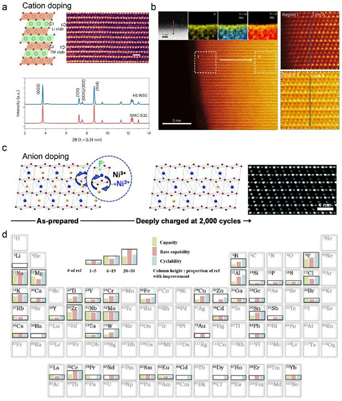
Anion doping involves incorporating anions or anionic groups into the lattice of the cathode material to modify its electronic structure and chemical properties. Common anionic dopants include F, Cl, S, and N, whose atomic radii are similar to oxygen, facilitating substitution for oxygen atoms in the layered structure [94,95]. Compared to cation doping, anion doping offers unique advantages in enhancing the electrochemical performance of cathode materials: (1) Suppression of TM dissolution: Anion doping at the 6c oxygen site effectively strengthens the bond energy between anions and metals, hindering the migration of TM ions from the lattice framework and reducing their dissolution. (2) Enhanced structural stability: The introduction of anions reinforces connectivity within the crystal structure, reducing structural deformation and thereby improving the durability of the cathode under extreme conditions such as high temperature or high voltage [96]. Sun et al. systematically investigated the impact of F- anion doping on the stability of HNLOs cathodes. Their results indicated that F- effectively suppressed the degree of Li+/Ni2+ cation mixing (Fig. 5c). This was attributed to the introduction of additional negative charge by doped F-, which provided charge compensation and inhibited the reduction of Ni3+ to Ni2+, consequently reducing Li+/Ni2+ mixing [97]. Additionally, typical polyanions such as PO43- exhibit outstanding structural stability owing to the strong covalent nature of P-O bonds within the PO43- tetrahedral units [98–100]. This unique feature effectively stabilizes the TM (3d)-O (2p) bonds. Moreover, the large ionic radius of PO43- (2.38 Å) induces localized structural distortion when incorporated into tetrahedral interstitial sites of the TM layer, generating defects that suppress phase transitions and reinforce the material’s structural integrity. These advantages have motivated researchers to apply PO43- tetrahedral polyanions in modifying the architecture of HNLOs. Sun and co–workers introduced PO43- into the HNLOs structure and demonstrated that such tetrahedral doping not only enlarges Li+ transport pathways but also inhibits cation rearrangement [98]. Consequently, oxygen evolution and irreversible phase transitions are alleviated, ensuring long–term cycling stability, particularly under high current densities. Although anionic species play an irreplaceable role in stabilizing the framework of HNLOs cathodes, they also come with inherent drawbacks. For instance, Kong et al. used density functional theory (DFT) to systematically investigate how three common anionic dopants (e.g., F, S, and Cl) affect various properties of the model LiNiO2 cathode, including redox potential, ionic conductivity, Li/Ni mixing, lattice distortion, and Ni migration during delithiation [94]. Their findings revealed that while these anionic dopants improve certain characteristics, they simultaneously degrade others, indicating that anion doping exerts contradictory effects on battery voltage, rate capability, and structural stability of the cathode.
Additionally, cation-anion co–doping has also been explored as a strategy to holistically enhance the electrochemical performance of cathode materials [101]. This approach entails the concurrent introduction of cations (e.g., Mg2+, Al3+, Ti4+, Zr4+, Ta5+) and anions (e.g., F-, Br-, BO2-, PO43-) into the bulk lattice, where they partially substitute for TM/lithium and oxygen sites, thereby tuning ion transport characteristics and the crystal structure [102,103]. For instance, Liu and co–workers employed a one–pot synthesis to produce Mg2+ and F- co–doped LiNi0.8Co0.15Al0.05O2 (NCA) cathodes [104]. The incorporation of Mg2+ reduces Li+/Ni2+ cation mixing, while F- substitution diminishes the band overlap between TM d–orbitals and O2- p–orbitals, improving high–voltage cycling stability. Moreover, the co–doping of Mg2+ and F- enlarges the interlayer spacing in the lithium slab, enhancing the Li+ diffusion coefficient and enabling superior rate capability. Zheng et al. introduced tetravalent Zr4+ in combination with F- doping [105]. Their findings indicate that F- preferentially occupies oxygen sites and promotes the formation of oxygen vacancies, which accelerates the migration of Ni ions from NiO6 octahedra to LiO6 octahedra. In other words, Zr/F co–doping induces a substantial number of Ni2+ ions to migrate into the lithium layer, triggering atomic rearrangement through ordered occupancy of lithium sites. This surface atomic reordering increases the mechanical modulus of the HNLOs cathode and suppresses particle cracking caused by compressive stress concentration. More recently, Zhang’s team co–introduced high–valence Ta5+ (which exhibits a higher binding energy with oxygen) and low–electronegativity Br- into the lattice of an ultra–high–nickel cathode (LiNi0.92Co0.04Mn0.04O2) [106]. Their work demonstrates that the strong Ta-O bonds, together with the low electronegativity of Br-, synergistically alleviate electrostatic repulsion within the O-TM-O framework and suppress lattice oxygen release triggered by hybridization between TM 3d and O 2p orbitals. Overall, cation-anion co-doping combines the respective advantages of both dopant types, enabling synergistic modification of TM and oxygen sites within the lattice, reinforcing the oxygen framework, and substantially enhancing the structural stability of HNLOs cathodes.
However, co-doping strategies may introduce additional heteroatoms, triggering new interactions and phase transformation behaviors, which could negatively impact the structural stability and ion diffusion of the cathode material [107]. Simultaneously, the mechanism of doping strategies at the local structural scale remains insufficient. Therefore, there is an urgent need to develop novel doping strategies that can concurrently modulate particle morphology and local atomic structure. Furthermore, in-depth development of effective doping methodologies and elucidation of interaction mechanisms between different elements are crucial for inhibiting thermodynamically irreversible phase transitions and enhancing material stability. It is important to note that in bulk elemental doping methods, the introduction of electrochemically inactive elements into the bulk lattice reduces the proportion of electrochemically active material, potentially leading to a decrease in cathode capacity, which is not conducive to achieving high specific energy. Moreover, excessive doping can disrupt the layered crystal structure. Therefore, optimizing the dopant concentration for each specific cathode material is necessary, often involving a trial-and-error process. Recently, Kwon et al. summarized the comparative contributions of different dopant elements to the capacity, cycling stability, and rate capability of HNLOs cathode materials (Fig. 5d) [108].
Gradient structure design aims to address structural instability issues by constructing gradual gradients in elemental composition, concentration, or structure within HNLOs cathode material particles. These strategies primarily include shell concentration gradient, full concentration gradient, core-shell structure gradient, and multi-dimensional gradients. Shell concentration gradient design involves creating a progressive elemental concentration at the cathode material surface, controlling the redox reaction rate during charge/discharge by adjusting elemental concentrations in different layers. Full concentration gradient design systematically constructs an elemental concentration gradient throughout the entire particle, optimizing the material’s internal structure. Core-shell structure design involves coating a Ni-rich cathode material core with a lower-Ni-content shell material, achieving a synergistic advantage where the inner core provides high capacity and the outer shell ensures structural stability. While multi-dimensional gradients involve the design of cathode structures where element composition, concentration, phase structure, etc., all exhibit a gradient distribution.
In 2009, Sun et al. proposed a shell concentration gradient cathode material based on HNLOs cathode [109]. In this material, each particle featured a Ni-rich center and a Mn-rich outer layer, with Ni concentration gradually decreasing and Mn and Co concentrations increasing towards the surface. The Ni-rich core (LiNi0.8Co0.1Mn0.1O2) provided high capacity, while the outer layer (LiNi0.46Co0.23Mn0.31O2) enhanced thermal stability. Subsequently, researchers developed full concentration gradient (FCG) structured cathodes (Fig. 6a), where the concentrations of Ni and Mn gradually decreased and increased, respectively, from the particle center to the surface [110]. FCG cathodes were synthesized via a modified co-precipitation method involving the continuous variation of Ni/Mn/Co concentration ratios in the precursor solution over reaction time. The FCG-type LiNi0.75Co0.10Mn0.15O2 cathode exhibited a high specific capacity of 215 mAh/g and demonstrated exceptional cycling stability (i.e., 90% capacity retention after 1000 cycles in full cells) and good thermal stability. Building upon this foundation, a series of FCG structures were investigated to reveal the impact of elemental differences on cathode structure and electrochemical performance [111]. It was found that the cycling and thermal stability of the cathode improved with increasing shell thickness, but reversible capacity, rate capability, and low-temperature performance were adversely affected [112]. Furthermore, Liu et al. further validated the mechanical stability of concentration gradient high-nickel materials and compared the influence of Co and Mn concentrations on their mechanical properties [113]. The Co-rich surface effectively suppressed microcrack initiation due to its lower rigidity, while the Mn-rich core, with its higher rigidity, limited internal crack propagation, thus providing superior mechanical and structural stability. Subsequently, researchers optimized the gradient structure considering practical synthesis challenges, leading to the development of core-shell gradient structures. A multi-component ultra-high Ni LiNi0.9Co0.05Mn0.05O2 cathode material (CSG90) was successfully synthesized via co-precipitation [114]. This material comprised an ultra-high Ni LiNi0.94Co0.038Mn0.022O2 core and a shell (1.5 µm) composed of LiNi0.841Co0.077Mn0.082O2 with lower Ni content (Fig. 6b). The study revealed that, compared to the severe lattice distortion occurring in the core during the H2-H3 phase transition, the shell exhibited significantly reduced lattice strain during this transformation. This strain reduction helped alleviate the overall volume change of the particle, minimizing stress accumulation and lattice distortion within the core. Furthermore, the more stable shell structure reduced the oxidation reaction between Ni4+ and the electrolyte in the deeply delithiated state, thereby maintaining structural stability.
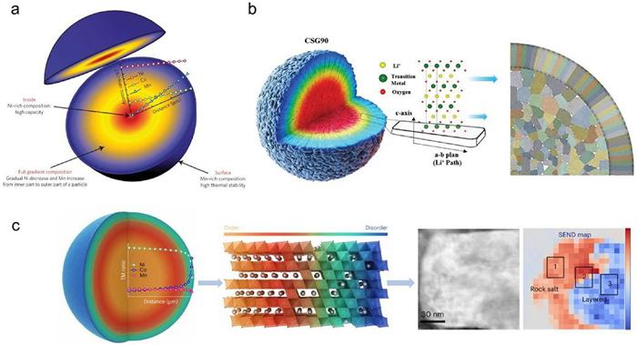
Recently, Liu et al. proposed a dual-gradient structured cathode featuring a coherent framework that transitions from ordered to disordered regions, with an increasing Co concentration and decreasing Ni concentration from the bulk to the surface (Fig. 6c), thereby overcoming the upper voltage limit constraint of HNLOs cathodes [115]. This design enabled simultaneous high capacity and high-voltage operation up to 4.7 V with negligible capacity fade. Multi-scale diffraction and imaging techniques revealed that the disordered surface possessed high electrochemical and structural stability, effectively suppressing surface parasitic reactions and phase transitions. The structural coherency from ordered to disordered lattices constrained lattice parameter changes, alleviated lattice strain, and enhanced morphological integrity. The dual-gradient design also significantly improved the material’s thermal stability, advancing the development of high-performance high-nickel cathodes. To reduce the surface nickel content and chemical reactivity of cathode materials, gradient structure design strategies tailor the internal chemical composition. This helps mitigate electrolyte-induced corrosion and improve structural stability. Nevertheless, this approach is not without limitations [116,117]: (1) Increased synthesis complexity—producing concentration-gradient structures often relies on specialized chemical synthesis techniques, which raises production difficulty and cost. (2) Reduced energy density—the incorporation of core-shell or concentration-gradient architectures takes up space within the active material, thereby decreasing the available capacity for lithium-ion storage.
Beyond the commonly employed surface coating, bulk doping, and gradient design strategies, recent research has developed a range of novel structure control methods, such as particle morphology control, defect engineering, crystallographic plane regulation, and structural optimization, to enhance the chemo-electro-mechanical stability of HNLOs cathodes.
In morphology control, Sun et al. employed a two-step synthesis strategy to synthesize nanostructured multiphase HNLOs cathodes (Fig. 7a) [118]. The nanoscale primary particles contributed to improved mechanical stability and suppression of intergranular cracks. Simultaneously, the as-prepared material exhibited a layered-rock salt nanostructured multiphase, which reversibly transformed into a layered-spinel nanostructured multiphase upon battery charging, facilitating rapid Li+ diffusion. This nanostructured Ni-rich multiphase cathode active material demonstrated excellent high-rate performance in both lithium metal coin cells and lithium-ion pouch cells, and showed application potential in lithium-ion pouch cells tested under electric vertical takeoff and landing protocols.
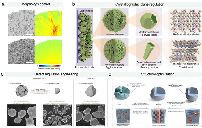
In crystallographic plane regulation, different crystal planes typically possess distinct surface energies, atomic arrangements, and surface reactivity with the electrolyte. These characteristics significantly influence Li+ diffusion kinetics, TM segregation, material crystallinity, and surface reconstruction in HNLOs cathodes. By exposing more active facets, such as (012), (104), and (010) planes, the effective Li+ diffusion pathways and diffusion kinetics can be substantially increased, thereby enhancing the cathode's capacity and rate capability [119,120]. Conversely, exposing more inactive facets, such as (001) planes, can effectively suppress parasitic side reactions with the electrolyte and unfavorable surface phase transformations, thereby improving cycling stability under high voltage [121]. Recently, Jiao’s team developed a quantitative single-particle method combining electrochemical impedance spectroscopy and three-dimensional geometrical reconstruction [122]. For the first time, they experimentally measured the intrinsic exchange current densities (j0) of six representative crystal facets of an NCM811 particle. This revealed significant differences in electrochemical kinetics among different crystal facets, identifying the (003) facet as the kinetically slowest interface in NCM811 material and a key factor limiting its high-rate performance. The j0 of the (201) facet was approximately 1.50 mA/cm2, about 25 times that of the (003) facet. Guided by the strategy of reducing the proportion of the slow-kinetics (003) facet, they successfully designed and fabricated an anisotropic core-shell structured NCM811 cathode material (Fig. 7b). This effectively reduced the proportion of the (003) facet with sluggish reaction kinetics, achieving a high capacity of 144 mAh/g at a high rate of 10 C and excellent stability over more than 500 cycles for the HNLOs cathode.
In defect engineering, Kang’s team utilized in-situ transmission electron microscopy to real-time detect the changes in phase transition structure and morphology during the solid-phase synthesis of LiNi0.6Co0.2Mn0.2O2 cathode materials [123]. They discovered that thermal decomposition within the HNLOs bulk material led to intrinsic microstructural defects, internal voids, and intragranular nanopores, which were detrimental to the electrochemical stability of high-nickel cathodes. Based on an understanding of the underlying thermodynamic and kinetic mechanisms, the authors proposed a quasi-equilibrium route for synthesizing HNLOs materials. Using an improved two-step sintering strategy, they successfully suppressed the formation of internal voids and nanopores within the cathode, resulting in excellent cycling stability. This work underscored the importance of multi-scale probing and controlling intrinsic structural defects during real-time reaction processes in investigating the chemo-mechanical properties of high-nickel cathodes. Recently, this team synthesized an ultra-high Ni single-crystal cathode free of cation disorder with a particle size of approximately 10 µm (comparable to commercial secondary particles) via an innovative ion-exchange method (Fig. 7c) [124]. This material exhibited high volumetric capacity and stable cycling performance. The study demonstrated the crucial role of a cation-disorder-free structure in suppressing key degradation behaviors such as strain and slippage, and also proved that eliminating structural defects is the core path to enhancing the chemo-mechanical stability of single crystals under high compaction density and high voltage conditions.
In structural optimization, drawing inspiration from the fast Li+ transport kinetics observed in polycrystalline HNLOs and the structural stability inherent to single-crystal HNLOs, Yang et al. proposed that the key to solving the current challenges of stability and synthesis for ultra-high Ni single-crystal cathodes lies in structural optimization—combining the advantages of both single-crystal and poly-crystal morphologies to achieve structural stability and accelerated Li+ transport [125]. Their team designed an ultra-high Ni single-crystal LiNi0.92Co0.03Mn0.05O2 (IBP-SC92) by constructing an intralattice-bonded phase (IBP) within the bulk of the ultra-high Ni single crystal. This IBP phase served both as “rivets” to enhance structural robustness and as “high-speed channels” to improve the Li+ migration rate, inhibiting detrimental lattice distortion and reaction inhomogeneity in the ultra-high Ni cathode, thereby maintaining structural integrity during cycling (Fig. 7d). Furthermore, our group has recently developed a series of general chemical delithiation strategies that enable dual optimization of the heterostructure and lattice structure at the surface of HNLOs cathodes [126–128]. Specifically, the chemical delithiation process drives the formation of island-like LiLaO2, Li2ZrO3 and Li2WO4 ionic conductors alongside tunable-thickness disordered rock-salt nanolayers. This structural modulation endows HNLO cathodes with concurrently enhanced ionic transport, reduced chemical reactivity, and improved mechanical robustness, substantially enhancing their long-term cycling stability and rate capability.
The relentless pursuit of higher energy density in LIBs has rendered HNLOs one of the premier cathode candidates for next-generation electric vehicles and grid-scale energy storage. However, as elucidated throughout this review, the trajectory toward high–Ni compositions is intrinsically accompanied by a cascade of interconnected degradation phenomena that span electronic, chemical, structural, and mechanical length scales [18,54]. The very features that enable high capacity—the Ni3+/4+ redox couple and the increased covalency of TM-O bonds at deep delithiation—simultaneously render the material susceptible to surface parasitic reactions, irreversible lattice oxygen release, progressive cation mixing with layered–to–rock–salt phase transformation, and catastrophic mechanical failure. These degradation modes are not independent; rather, they form a synergistic feedback loop: Oxygen release exacerbates surface reconstruction, which accelerates electrolyte decomposition, while chemo–mechanical strain nucleates intergranular and intragranular cracks that expose fresh surfaces to further attack. Understanding this coupled chemical–structural–mechanical failure mechanism has therefore become the central paradigm guiding the design of durable high–nickel cathodes.
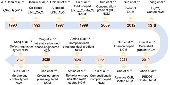
In response to these multi–faceted challenges, the modification strategies reviewed herein—surface coating, bulk heterovalent element doping, gradient architecture, and novel structural controls—have evolved from empirical trial–and–error to rational, mechanism–inspired designs (Fig. 8). Given the extremely high chemical reactivity of the charged HNLOs cathode surface, constructing a coating layer to physically isolate the cathode from the electrolyte and suppress interfacial side reactions has become a primary approach. Surface coatings have progressed from simple inert barriers (e.g., Al2O3) to functional layers such as fast ion conductors (Li3PO4), conductive polymers (PEDOT), and epitaxial entropy–stabilized oxides that simultaneously block side reactions, facilitate Li+ transport, and scavenge detrimental species like HF. Recognizing the limitations of surface coating in stabilizing the bulk lattice of HNLOs, bulk heterovalent element doping has advanced beyond mere substitution at TM sites to include high–valence “pillar” ions (e.g., Nb5+, W6+, Ta5+) that not only suppress Li/Ni mixing and lattice parameter changes but also tailor primary particle morphology to radially orient grain boundaries, thereby dispersing anisotropic stress during the H2-H3 phase transition. To better synergize the stabilization of both the surface and bulk structures of the cathode, gradient structure designs have demonstrated remarkable success in reconciling the capacity-stability trade–off by concentrating Ni in the particle core for high energy while enriching Mn or Co at the surface to passivate reactivity and buffer volume changes. However, gradient structure designs often rely on complex synthesis processes, incur high costs, and sacrifice some usable capacity, which poses difficulties for commercial viability. More recently, innovative strategies such as intragranular “rivet” phases, cation–disorder–free single crystals synthesized via ion exchange, crystallographic facet engineering, and structural optimization strategies have opened new frontiers for simultaneously enhancing mechanical integrity and Li+ transport kinetics. These strategies exhibit prominent advantages in addressing the multi–dimensional failure issues of HNLOs under high cut–off voltages.
Despite these substantial advances, critical gaps remain that must be addressed to translate laboratory–scale successes into commercially viable, ultrahigh–energy HNLOs cathodes. First, the majority of modification strategies have been developed and optimized for HNLOs cathode under relatively mild testing conditions (e.g., moderate cutoff voltages ≤ 4.5 V, limited cycle numbers). Their efficacy for ultra–high–nickel cathodes (Ni content ≥92%) under extreme conditions—such as high–energy irradiation, fast charging, higher voltage (≥4.6 V), elevated temperatures, and the high mass loadings required for practical cells—remains insufficiently validated. Second, the interplay between different degradation mechanisms and the synergistic effects of combined modification strategies (e.g., multi-scale structure control) are still poorly understood at a quantitative level. Third, the characterization of degradation and modification efficacy has largely relied on ex situ or post–mortem techniques, which may miss transient, metastable states critical to failure initiation. Operando and in situ methods with high spatial and temporal resolution—such as advanced synchrotron–based diffraction/spectroscopy, environmental high-resolution TEM, and neutron scattering—are urgently needed to capture the dynamic evolution of lattice strain, oxygen redox, and interface chemistry during cycling. Fourth, existing modification strategies remain unable to stabilize ultra–high–nickel cathodes under harsh operating conditions such as high voltage, and emerging modification methods still fall short of the low–cost, sustainable, and scalable requirements for commercial production of stable, high–energy cathodes.
Looking forward, we envision that the next generation of ultra–high–nickel cathodes will emerge from a holistic, multi–scale design philosophy that integrates chemical, structural, and mechanical regulation from the atomic to the electrode level. Several promising directions warrant intensified investigation:
(1) Atomistic to mesoscale understanding of coupled failure for ultra–high–nickel cathodes under extreme conditions such as high working voltage. Advanced computational methods (DFT, machine–learning force fields, phase–field modeling) combined with high–resolution characterization should be employed to unravel the causal relationships between oxygen vacancy formation/distribution, TM migration, phase distortion/transformation, and microcrack nucleation/propagation. Identifying the critical thresholds—e.g., the degree of delithiation or local lattice strain at which the H2-H3 transition becomes irreversible—will enable predictive design of detailed composition and structure of ultra–high–nickel cathodes. These computational tools, combined with machine learning algorithms, can predict optimal compositions and processing conditions, accelerating materials development from years to months.
(2) Development of synthesis and modification methods tailored for ultra–high–specific–energy HNLOs cathode systems. New efficient synthetic routes should be designed to prepare ultra–high–nickel cathodes, enabling higher specific capacity at the cathode level. Concurrently, building upon the multi–dimensional failure mechanisms of ultra–high–nickel systems described above, novel synergistic modification strategies should be established that are applicable to ultra–high–nickel cathodes under high cut–off voltages (≥ 4.6 V), thereby achieving ultra–stable long-term cycling of ultra–high–energy cathodes under high voltage.
(3) Further optimization and upgrading of sustainable and scalable synthesis/modification methods for commercial applications. Many advanced modification strategies involve complex, multi–step processes (e.g., co–precipitation for gradient structures, ALD for uniform coatings) that are difficult to scale economically. Developing simplified, continuous, or one–pot synthesis methods that achieve similar levels of structural precision is essential for commercial adoption. Moreover, reducing reliance on scarce or costly elements (e.g., Co, Ta) through alternative high–valence dopants or novel anion redox chemistries should be a priority.
In conclusion, the journey toward ultrahigh–energy, durable LIBs hinges on our ability to master the complex degradation chemistry of ultra–high–nickel cathodes under high working voltages. The field has progressed from phenomenological observation to mechanistic understanding and, increasingly, to precise intervention at the atomic and mesoscopic scales. By embracing a holistic perspective that treats chemical stability, structural integrity, and mechanical resilience as inseparable facets of a single materials challenge—and by leveraging emerging tools in characterization, computation, and synthesis—we are poised to unlock the next plateau of battery performance. The roadmap outlined herein, centered on the innovation of coupled chemical–structural–mechanical regulation, provides a strategic framework to guide this endeavor, ultimately enabling the widespread deployment of ultra–high–energy cathodes that are not only powerful but also safe and long–lasting.
Jun Wang: Writing – review & editing, Writing – original draft, Visualization, Validation, Software, Methodology, Investigation, Formal analysis, Data curation, Conceptualization. Ting Liu: Writing – review & editing, Visualization, Validation, Investigation, Data curation. Juping Xu: Visualization, Validation, Investigation. Guanjie Zhang: Validation, Investigation. Yan Zhao: Visualization, Investigation. Huaican Chen: Writing – review & editing, Supervision, Software, Resources, Funding acquisition. Jinxiang Fan: Visualization, Validation. Sijie Guo: Validation, Investigation, Funding acquisition. Sidong Zhang: Writing – review & editing, Validation, Supervision, Investigation, Funding acquisition. Wen Yin: Writing – review & editing, Visualization, Validation, Supervision, Project administration, Formal analysis, Conceptualization. An-Min Cao: Writing – review & editing, Visualization, Validation, Supervision, Resources, Project administration, Investigation, Funding acquisition, Conceptualization.
The authors declare that they have no known competing financial interests or personal relationships that could have appeared to influence the work reported in this paper.
This work was supported by the National Natural Science Foundation of China (Nos. 22539003, 22421001, 22409200 and 22409212), the Strategic Priority Research Program of the Chinese Academy of Sciences, No. XDB 1040200, and Ningbo Key Laboratory of All-Solid-State Battery.
J.Y. Li, Z.Y. Hu, S.D. Zhang, et al., Nat. Sustain. 7 (2024) 1481–1491. doi: 10.1038/s41893-024-01414-7
S.D. Zhang, M.Y. Qi, S.J. Guo, et al., Energy Storage Mater. 57 (2023) 289–298. doi: 10.1016/j.ensm.2023.02.024
K. Kang, Y.S. Meng, J. Bréger, C.P. Grey, G. Ceder, Science 311 (2006) 977–980. doi: 10.1126/science.1122152
G. Harper, R. Sommerville, E. Kendrick, et al., Nature 575 (2019) 75–86. doi: 10.1038/s41586-019-1682-5
F. Degen, M. Winter, D. Bendig, J. Tübke. Nat. Energy 8 (2023) 1284–1295. doi: 10.1038/s41560-023-01355-z
W. Teng, Z. Li, J. Cheng, et al., Chin. Chem. Lett. (2025), doi: 10.1016/j.cclet.2025.111996.
W. Li, E.M. Erickson, A. Manthiram. Nat. Energy 5 (2020) 26–34. doi: 10.1038/s41560-019-0513-0
J. Xu, X. Cai, S. Cai, et al., Energy Environ. Mater. 6 (2023) e12450. doi: 10.1002/eem2.12450
M. Bianchini, M. Roca-Ayats, P. Hartmann, T. Brezesinski, J. Janek, Angew. Chem. Int. Ed. 58 (2019) 10434–10458. doi: 10.1002/anie.201812472
J.R. Dahn, U. von Sacken, C.A. Michal, Solid. State Ion. 44 (1990) 87–97. doi: 10.1016/0167-2738(90)90049-W
Z. Liu, A. Yu, J.Y. Lee, J. Power Sources 81-82 (1999) 416–419. doi: 10.1016/S0378-7753(99)00221-9
R.V. Chebiam, F. Prado, A. Manthiram, Chem. Mater. 13 (2001) 2951–2957. doi: 10.1021/cm0102537
T. Ohzuku, A. Ueda, M. Nagayama, Y. Iwakoshi, H. Komori, Electrochim. Acta 38 (1993) 1159–1167. doi: 10.1016/0013-4686(93)80046-3
R. Zhang, C. Wang, P. Zou, et al., Nature 610 (2022) 67–73. doi: 10.1038/s41586-022-05115-z
Y. Zheng, J. Li, Y. Liu, et al., Energy Environ. Mater. 9 (2026) e70152. doi: 10.1002/eem2.70152
Z. Cui, A. Manthiram, Angew. Chem. Int. Ed. 62 (2023) e202307243. doi: 10.1002/anie.202307243
M. Dixit, B. Markovsky, F. Schipper, D. Aurbach, D.T. Major, J. Phys. Chem. C 121 (2017) 22628–22636. doi: 10.1021/acs.jpcc.7b06122
Z. Liu, Y. Zhang, S. Pan, et al., Energy Environ. Sci. 19 (2026) 84–125. doi: 10.1039/d5ee04213e
J. Sicklinger, M. Metzger, H. Beyer, D. Pritzl, H.A. Gasteiger, J. Electrochem. Soc. 166 (2019) A2322. doi: 10.1149/2.0011912jes
Z. Cui, P. Zuo, Z. Guo, C. Wang, A. Manthiram, Adv. Mater. 36 (2024) 2402420. doi: 10.1002/adma.202402420
Y. Xie, J. Li, M. Li, et al., Adv. Funct. Mater. 34 (2024) 2311551. doi: 10.1002/adfm.202311551
L. Yu, J. Wang, T. Zhou, et al., Nat. Commun. 16 (2025) 6519. doi: 10.1038/s41467-025-61304-0
B. Namkoong, N.Y. Park, G.T. Park, et al., Adv. Energy Mater. 12 (2022) 2200615. doi: 10.1002/aenm.202200615
N.Y. Park, M.C. Kim, S.M. Han, et al., Angew. Chem. Int. Ed. 63 (2024) e202319707. doi: 10.1002/anie.202319707
J. Tian, G. Wang, W. Zeng, et al., Energy Storage Mater. 68 (2024) 103344. doi: 10.1016/j.ensm.2024.103344
L. Mu, R. Lin, R. Xu, et al., Nano Lett. 18 (2018) 3241–3249. doi: 10.1021/acs.nanolett.8b01036
Y. Chu, Y. Mu, L. Zou, et al., ChemElectroChem 11 (2024) e202300653. doi: 10.1002/celc.202300653
H.H. Ryu, K.J. Park, C.S. Yoon, Y.K. Sun, Chem. Mater. 30 (2018) 1155–1163. doi: 10.1021/acs.chemmater.7b05269
L. Ma, M. Nie, J. Xia, J.R. Dahn, J. Power Sources 327 (2016) 145–150. doi: 10.1016/j.jpowsour.2016.07.039
S. Lee, L. Su, A. Mesnier, Z. Cui, A. Manthiram, Joule 7 (2023) 2430–2444. doi: 10.1016/j.joule.2023.09.006
W. Xue, M. Huang, Y. Li, et al., Nat. Energy 6 (2021) 495–505. doi: 10.1038/s41560-021-00792-y
R. Jung, M. Metzger, F. Maglia, C. Stinner, H.A. Gasteiger, Phys. Chem. Lett. 8 (2017) 4820–4825. doi: 10.1021/acs.jpclett.7b01927
W.M. Dose, W. Li, I. Temprano, et al., ACS Energy Lett. 7 (2022) 3524–3530. doi: 10.1021/acsenergylett.2c01722
W. Yang, X. Liu, R. Qiao, et al., J. Electron. Spectrosc. Relat. Phenom. 190 (2013) 64–74. doi: 10.1016/j.elspec.2013.03.008
I. Takahashi, H. Kiuchi, A. Ohma, T. Fukunaga, E. Matsubara, J. Phys. Chem. C 124 (2020) 9243–9248. doi: 10.1021/acs.jpcc.0c02198
J. Yang, X. Liang, H.H. Ryu, C.S. Yoon, Y.K. Sun, Energy Storage Mater. 63 (2023) 102969. doi: 10.1016/j.ensm.2023.102969
Y. Zhang, Y. Katayama, R. Tatara, et al., Energy Environ. Sci. 13 (2020) 183–199. doi: 10.1039/c9ee02543j
Y. Yu, P. Karayaylali, Y. Katayama, et al., J. Phys. Chem. C 122 (2018) 27368–27382. doi: 10.1021/acs.jpcc.8b07848
L. Giordano, P. Karayaylali, Y. Yu, et al., Phys. Chem. Lett. 8 16 (2017) 3881–3887. doi: 10.1021/acs.jpclett.7b01655
T. Kim, L.K. Ono, N. Fleck, S.R. Raga, Y. Qi, J. Mater. Chem. A 6 (2018) 14449–14463. doi: 10.1039/c8ta02622j
P. Hou, J. Yin, M. Ding, J. Huang, X. Xu, Small 13 (2017) 1701802. doi: 10.1002/smll.201701802
H. Yu, H. Zhu, H. Jiang, et al., Natl. Sci. Rev. 10 (2023) nwac166. doi: 10.1093/nsr/nwac166
M. Cai, Y. Dong, M. Xie, et al., Nat. Energy 8 (2023) 159–168. doi: 10.1038/s41560-022-01179-3
H. Chen, T. Ericson, R.H. Temperton, et al., ACS Appl. Energy Mater. 6 (2023) 11458–11467. doi: 10.1021/acsaem.3c01621
D. Streich, C. Erk, A. Guéguen, et al., J. Phys. Chem. C 121 (2017) 13481–13486. doi: 10.1021/acs.jpcc.7b02303
Q. Li, Q. Liang, H. Zhang, et al., Angew. Chem. Int. Ed. 62 (2023) e202215131. doi: 10.1002/anie.202215131
Y. Wang, J. Jiang, J.R. Dahn, Electrochem. Commun. 9 (2007) 2534–2540. doi: 10.1016/j.elecom.2007.07.033
Z. Cui, C. Liu, F. Wang, A. Manthiram, Nat. Energy 10 (2025) 490–501. doi: 10.1038/s41560-025-01731-x
T. Yang, K. Zhang, Y. Zuo, et al., Nat. Sustain. 7 (2024) 1204–1214. doi: 10.1038/s41893-024-01402-x
S.M. Bak, K.W. Nam, W. Chang, et al., Chem. Mater. 25 (2013) 337–351. doi: 10.1021/cm303096e
S. Li, Z. Yao, J. Zheng, et al., Angew. Chem. Int. Ed. 59 (2020) 22092–22099. doi: 10.1002/anie.202008144
Q. Huang, X. Zhang, X. Lv, et al., Adv. Mater. 37 (2025) 2419872. doi: 10.1002/adma.202419872
S. Hwang, W. Chang, S.M. Kim, et al., Chem. Mater. 26 (2014) 1084–1092. doi: 10.1021/cm403332s
A. Manthiram, Z. Cui, Nat. Energy 11 (2026) 517–525. doi: 10.1038/s41560-025-01963-x
C. Liu, S. Reed, A. Manthiram, Adv. Mater. 37 (2025) e09889. doi: 10.1002/adma.202509889
S.K. Jung, H. Gwon, J. Hong, et al., Adv. Energy Mater. 4 (2014) 1300787. doi: 10.1002/aenm.201300787
L. Zou, Z. Liu, W. Zhao, et al., Chem. Mater. 30 (2018) 7016–7026. doi: 10.1021/acs.chemmater.8b01958
Q. Lin, W. Guan, J. Meng, et al., Nano Energy 54 (2018) 313–321. doi: 10.1016/j.nanoen.2018.09.066
H. Zhang, H. Liu, L.F.J. Piper, M.S. Whittingham, G. Zhou, Chem. Rev. 122 (2022) 5641–5681. doi: 10.1021/acs.chemrev.1c00327
X. Cheng, Y. Li, T. Cao, et al., ACS. Energy Lett. 6 (2021) 1703–1710. doi: 10.1021/acsenergylett.1c00279
Y. Han, C. Zheng, Z. Liu, et al., Energy Environ. Mater. 9 (2026) e70160. doi: 10.1002/eem2.70160
M. Jiang, D.L. Danilov, R.A. Eichel, P.H.L. Notten, Adv. Energy Mater. 11 (2021) 2103005. doi: 10.1002/aenm.202103005
S.S. Zhang, J. Energy Chem. 41 (2020) 135–141. doi: 10.1016/j.jechem.2019.05.013
P. Yan, J. Zheng, M. Gu, et al., Nat. Commun. 8 (2017) 14101. doi: 10.1038/ncomms14101
Y. Bi, J. Tao, Y. Wu, et al., Science 370 (2020) 1313–1317. doi: 10.1126/science.abc3167
Z. Tan, X. Chen, J. Lin, et al., Angew. Chem. Int. Ed. 64 (2025) e202419903. doi: 10.1002/anie.202419903
W. Huang, T. Liu, L. Yu, et al., Science 384 (2024) 912–919. doi: 10.1126/science.ado1675
W. Wang, Z. Li, J. Wang, et al., Nat. Commun. 17 (2026) 1421. doi: 10.1038/s41467-025-68166-6
G. Kaur, B.D. Gates, J. Electrochem. Soc. 169 (2022) 043504. doi: 10.1149/1945-7111/ac60f3
T. Weigel, F. Schipper, E.M. Erickson, et al., ACS Energy Lett. 4 (2019) 508–516. doi: 10.1021/acsenergylett.8b02302
Y. Zhang, X. Xu, C. Li, et al., Energy Storage Mater. 84 (2026) 104757. doi: 10.1016/j.ensm.2025.104757
N.Y. Park, H.U. Lee, T.Y. Yu, et al., Nat. Energy 10 (2025) 479–489. doi: 10.1038/s41560-025-01726-8
H.H. Ryu, H.W. Lim, S.G. Lee, Y.K. Sun, Nat. Energy 9 (2024) 47–56.
Z. Wu, Y. Li, L. Xian, et al., Chin. Chem. Lett. (2026), doi:10.1016/j.cclet.2026. 112537.
J. Cabana, B.J. Kwon, L. Hu, Acc. Chem. Res. 51 (2018) 299–308. doi: 10.1021/acs.accounts.7b00482
U. Nisar, N. Muralidharan, R. Essehli, R. Amin, I. Belharouak, Energy Storage Mater. 38 (2021) 309–328. doi: 10.1016/j.ensm.2021.03.015
J. Yan, H. Huang, J. Tong, et al., Interdiscip. Mater. 1 (2022) 330–353. doi: 10.1002/idm2.12043
Z. Chen, Y. Qin, K. Amine, Y.K. Sun, J. Mater. Chem. 20 (2010) 7606–7612. doi: 10.1039/c0jm00154f
H. Yu, Y. Cao, L. Chen, et al., Nat. Commun. 12 (2021) 4564. doi: 10.1038/s41467-021-24893-0
P. Yan, J. Zheng, J. Liu, et al., Nat. Energy 3 (2018) 600–605. doi: 10.1038/s41560-018-0191-3
G.L. Xu, Q. Liu, K.K.S. Lau, et al., Nat. Energy 4 (2019) 484–494. doi: 10.1038/s41560-019-0387-1
M. Yoon, Y. Dong, J. Hwang, et al., Nat. Energy 6 (2021) 362–371. doi: 10.1038/s41560-021-00782-0
Y.H. Du, H. Sheng, X.H. Meng, et al., Nano Energy 94 (2022) 106901. doi: 10.1016/j.nanoen.2021.106901
Y. Wu, Q. Wu, Z. Zeng, et al., Sci. Bull. 70 (2025) 2473–2482. doi: 10.1016/j.scib.2025.05.035
C. Zhao, C. Wang, X. Liu, et al., Nat. Energy 9 (2024) 345–356. doi: 10.1038/s41560-024-01465-2
T. Ohzuku, T. Yanagawa, M. Kouguchi, A. Ueda, J. Power Sources 68 (1997) 131–134. doi: 10.1016/S0378-7753(97)02516-0
Z. Cui, X. Li, X. Bai, X. Ren, X. Ou, Energy Storage Mater. 57 (2023) 14–43. doi: 10.1016/j.ensm.2023.02.003
Q. Xie, W. Li, A. Manthiram, Chem. Mater. 31 (2019) 938–946. doi: 10.1021/acs.chemmater.8b03900
R.P. Qing, J.L. Shi, D.D. Xiao, et al., Adv. Energy Mater. 6 (2016) 1501914. doi: 10.1002/aenm.201501914
R. Zhang, C. Wang, P. Zou, et al., Nat. Energy 8 (2023) 695–702. doi: 10.1038/s41560-023-01267-y
H. Liao, Y. Tang, W. Ma, et al., Nat. Energy 10 (2025) 1107–1115. doi: 10.1038/s41560-025-01831-8
J. Zhou, J. Hu, Z. Shang, et al., Adv. Energy Mater. 16 (2026) e05196. doi: 10.1002/aenm.202505196
L. Liang, M. Su, Z. Sun, et al., Sci. Adv. 10 (2024) eado4472. doi: 10.1126/sciadv.ado4472
F. Kong, C. Liang, R.C. Longo, et al., Chem. Mater. 28 (2016) 6942–6952. doi: 10.1021/acs.chemmater.6b02627
J.O. Binder, S.P. Culver, R. Pinedo, et al., ACS Appl. Mater. Interfaces 10 (2018) 44452–44462. doi: 10.1021/acsami.8b16049
Z. Tan, F. Xu, T. Wu, et al., Energy Storage Mater. 74 (2025) 103949. doi: 10.1016/j.ensm.2024.103949
U.H. Kim, G.T. Park, P. Conlin, et al., Energy Environ. Sci. 14 (2021) 1573–1583. doi: 10.1039/d0ee03774e
L. Cong, Q. Zhao, Z. Wang, et al., Electrochim. Acta 201 (2016) 8–19. doi: 10.1016/j.electacta.2016.03.088
W. Cheng, Q. Liu, J. Ding, et al., Small 19 (2023) 2301564. doi: 10.1002/smll.202301564
W. Zheng, G. Liang, H. Guo, et al., Energy Environ. Sci. 17 (2024) 4147–4156. doi: 10.1039/d4ee00726c
L. Qiu, W. Xiang, W. Tian, et al., Nano Energy 63 (2019) 103818. doi: 10.1016/j.nanoen.2019.06.014
H. Wang, J. Dong, H. Zhang, et al., J. Energy Chem. 106 (2025) 9–19. doi: 10.1016/j.jechem.2025.01.077
X. He, J. Shen, B. Zhang, et al., Adv. Funct. Mater. 34 (2024) 2401300. doi: 10.1002/adfm.202401300
Y. Zhou, H. Zhang, Y. Wang, et al., ACS Nano 17 (2023) 20621–20633. doi: 10.1021/acsnano.3c07655
Y. Huang, P. Li, H. Wei, et al., ACS Nano 19 (2025) 23719–23731. doi: 10.1021/acsnano.5c03464
J. Shen, Z. Cao, Z. Li, et al., Adv. Funct. Mater. 35 (2025) 2502419. doi: 10.1002/adfm.202502419
S.S. Zhang, Energy Storage Mater. 24 (2020) 247–254. doi: 10.1016/j.ensm.2019.08.013
G. Ko, S. Jeong, S. Park, et al., Energy Storage Mater. 60 (2023) 102840. doi: 10.1016/j.ensm.2023.102840
Y.K. Sun, S.T. Myung, B.C. Park, et al., Nat. Mater. 8 (2009) 320–324. doi: 10.1038/nmat2418
Y.K. Sun, Z. Chen, H.J. Noh, et al., Nat. Mater. 11 (2012) 942–947. doi: 10.1038/nmat3435
C. Zhang, T. Li, B. Xue, et al., Chem. Eng. J. 451 (2023) 138518. doi: 10.1016/j.cej.2022.138518
E.J. Lee, H.J. Noh, C.S. Yoon, Y.K. Sun, J. Power Sources 273 (2015) 663–669. doi: 10.1016/j.jpowsour.2014.09.161
T. Liu, L. Yu, J. Lu, et al., Nat. Commun. 12 (2021) 6024. doi: 10.1038/s41467-021-26290-z
U.H. Kim, H.H. Ryu, J.H. Kim, et al., Adv. Energy Mater. 9 (2019) 1803902. doi: 10.1002/aenm.201803902
T. Liu, L. Yu, J. Liu, et al., Nat. Energy 9 (2024) 1252–1263. doi: 10.1038/s41560-024-01605-8
K. Wu, J. Wang, Q. Li, et al., Nanoscale 12 (2020) 11182–11191. doi: 10.1039/d0nr01557a
L. Liang, W. Zhang, F. Zhao, et al., Adv. Mater. Interfaces 7 (2020) 1901749. doi: 10.1002/admi.201901749
N.Y. Park, G.T. Park, J.H. Ryu, et al., Nat. Nanotechnol. 21 (2026) 240–248. doi: 10.1038/s41565-025-02092-y
Z. Meng, X. Ma, L. Azhari, J. Hou, Y. Wang, Commun. Mater. 4 (2023) 90. doi: 10.1038/s43246-023-00418-8
J. Zhu, G. Chen. J. Mater. Chem. A 7 (2019) 5463–5474. doi: 10.1039/c8ta10329a
J. Xiao, Y. Bi, S. Hwang, S. Danitz, B. Wu, Chem. Rev. 125 (2025) 11058–11082. doi: 10.1021/acs.chemrev.5c00485
X. Li, J. Huang, L. Yang, et al., Nat. Commun. 16 (2025) 10229. doi: 10.1038/s41467-025-65068-5
H. Park, H. Park, K. Song, et al., Nat. Chem. 14 (2022) 614–622. doi: 10.1038/s41557-022-00915-2
Y. Jeon, D. Eum, H.Y. Jang, et al., Nat. Energy 11 (2026) 76–86. doi: 10.1038/s41560-025-01909-3
Q. Zhang, J. Wang, Y. Chu, et al., Nat. Energy 10 (2025) 1001–1012. doi: 10.1038/s41560-025-01827-4
M.Y. Qi, S.D. Zhang, S. Guo, et al., Small Methods 7 (2023) 2300280. doi: 10.1002/smtd.202300280
S.Q. Lu, Q. Zhang, F. Meng, et al., J. Am. Chem. Soc. 145 (2023) 7397–7407. doi: 10.1021/jacs.2c13787
S. Zhang, P. Ji, S. Guo, et al., J. Energy Chem. 114 (2026) 52–59. doi: 10.1016/j.jechem.2025.09.091

Figure 1 Venn diagram summarizing the multi-scale coupled failure mechanisms and stabilization strategies of current high-energy HNLOs cathodes.

Figure 2 Chemical, atomic and lattice-scale coupled failure processes of HNLOs cathodes during delithiation. (a) Schematic illustration of the evolution of the band structure and the HOMO/LUMO levels at the interface between the HNLOs cathode and the electrolyte upon delithiation. Reproduced with permission [49]. Copyright 2024, The Author(s). Reproduced with permission [35]. Copyright 2020, American Chemical Society. (b) Valence band structure model derived from independent computational studies to explain the structure-property relationship between chemical instability and oxygen release. Representative TM-O2* intermediates (zoom–in) are shown at (ⅰ) full lithiation, (ⅱ) maximum nickel oxidation, and (ⅲ) complete delithiation. Reproduced with permission [45]. Copyright 2017, American Chemical Society. (c) Evolution of lattice structure degradation of the HNLOs cathode during delithiation. Reproduced with permission [54]. Copyright 2026, Springer Nature. (d) Coupled failure of lattice oxygen release and irreversible phase transformation exhibited by the HNLOs cathode as delithiation proceeds. Reproduced with permission [55]. Copyright 2025, John Wiley and Sons.

Figure 3 Mechanical failure mechanisms of HNLOs cathodes during delithiation. (a) Distribution of equivalent stress in HNLOs cathodes at different states of delithiation. Reproduced with permission [60]. Copyright 2021, American Chemical Society. (b) Evolution of intragranular cracks in the cathode as a function of delithiation depth. Reproduced with permission [64]. Copyright 2017, The Author(s). (c) Irreversible lattice rotation phenomenon observed in HNLOs cathodes during delithiation. Reproduced with permission [67]. Copyright 2024, The American Association for the Advancement of Science. (d) Unrecoverable layer bending process that affects the kinetically controlled capacity loss of the cathode. Reproduced with permission [68]. Copyright 2026, The Author(s).

Figure 4 Design of different surface coating structures to stabilize HNLOs cathodes. (a) Amorphous Li3PO4 coating with high ionic conductivity. Reproduced with permission [80]. Copyright 2018, The Author(s). (b) Electronically conductive coating. Reproduced with permission [81]. Copyright 2019, Springer Nature. (c) Reactive wetting coating. Reproduced with permission [82]. Copyright 2021, The Author(s). (d) Epitaxial oriented growth coating. Reproduced with permission [85]. Copyright 2024, The Author(s).

Figure 5 Doping design with heterovalent elements to stabilize HNLOs cathodes. (a, b) Synergistic doping of cations with different valences to stabilize the lattice structure and facilitate rapid Li+ transport in HNLOs. Reproduced with permission [90]. Copyright 2023, The Author(s). Reproduced with permission [91]. Copyright 2025, The Author(s). (c) Negatively charged fluorine anion doping to suppress Li+/Ni2+ mixing. Reproduced with permission [97]. Copyright 2021, Royal Society of Chemistry. (d) Schematic illustration of the contribution of different doping elements to the capacity, cycling stability and rate performance of HNLOs cathodes. Reproduced with permission [108]. Copyright 2023, Elsevier.

Figure 6 Different gradient structural design strategies for stabilizing HNLOs cathodes. (a) Full concentration gradient structure. Reproduced with permission [110]. Copyright 2012, Springer Nature. (b) Core-shell gradient structure. Reproduced with permission [114]. Copyright 2019, John Wiley and Sons. (c) Dual gradient structure involving both composition and lattice arrangement. Reproduced with permission [115]. Copyright 2024, Springer Nature.

Figure 7 Novel structural control methods for stabilizing HNLOs cathodes. (a) Morphology control. Reproduced with permission [118]. Copyright 2025, The Author(s). (b) Crystallographic plane regulation. Reproduced with permission [122]. Copyright 2025, The Author(s). (c) Defect regulation engineering. Reproduced with permission [124]. Copyright 2026, The Author(s). (d) Structural optimization. Reproduced with permission [125]. Copyright 2025, The Author(s).

Figure 8 The roadmap of the development of modification strategies for HNLOs cathodes, including surface coating, bulk heterovalent doping, gradient structure design, and recently emerging novel regulation methods, illustrating their coupled progression in response to multi–dimensional failure mechanisms.

 扫一扫看文章


扫一扫关注我们
 DownLoad:
 下载:
 下载: