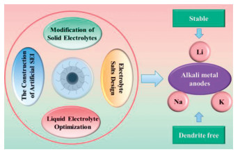
Figure 1.
Schematic illustration of the application of carbon dots (CDs) in stable and dendrite-free alkali metal anodes.

Emerging carbon dot-based nanomaterials for stable and dendrite-free alkali metal anodes: Applications and perspectives
Qian Zhou , Di Zhang , Fei Wang , Yanmei Liu , Fengzhou Li , Jing Wang , Cheng Zhang , Hongshuai Hou , Suya Hu , Longze Zhao , Fengzhang Ren , Hongxia Li , Yong Liu


The popularity of electrical power resources has led to a research boom in electrochemical energy storage systems including lithium-ion batteries, sodium-ion batteries, redox flow battery and so on [1–3]. Among them, lithium-ion batteries are widely used in daily life because of their long service life, low self-discharge rate, and low memory effect [4–6]. Nevertheless, the energy density of traditional lithium-ion batteries with graphite as an anode is close to its theoretical limit, and it is difficult to develop them further to meet the ever-increasing demand for high-energy-density battery applications, especially for electric vehicles, electric ships, eVTOL, and so on [7–9]. Therefore, it is necessary to explore new battery systems to achieve higher energy density [10,11].
It is worth noting that lithium metal batteries (LMBs) with lithium metal anodes are considered to be the most promising candidate battery system because of their low redox potential (−3.040 V vs. standard hydrogen electrode) and high theoretical capacity (3860 mAh/g) [4,5,12]. In addition to lithium metal, Na metal and K metal have the characteristics of low cost, high natural abundance, and similar physical and chemical properties to Li. Moreover, they also exhibit a high theoretical capacity (Na: 1166 mAh/g; K: 685 mAh/g) and low redox potential (Na: −2.71 V; K: −2.93 V vs. standard hydrogen electrode) [8,9,13]. Therefore, alkali metal batteries (AMBs) with Li, Na, and K as anodes have attracted more and more attention in various battery systems [14,15]. However, severe problems such as high reactivity, large volume expansion, and severe dendrite growth during cycling often lead to low Coulombic efficiency, a short service life, and even safety hazards of AMBs, which greatly hinder their practical application [9,16,17]. So far, many strategies have been adopted to overcome these problems, for example, new current collector designs, optimization of the liquid electrolyte, modifying the separator, constructing artificial solid electrolyte interfaces (SEIs) on metal anodes, and introducing a solid electrolyte [18–22].
Carbon dots (CDs), as a new type of zero-dimensional material in the carbon material family, have attracted widespread attention because of their abundant resources [23], high specific surface area [24], good conductivity [25], rich functional groups [26], good chemical stability [27], easy synthesis [28], low toxicity [29], and environmental friendliness [30–33]. In recent years, carbon dot-based nanomaterials (CDNMs) used in electrolytes and electrodes have been found to improve the ion conductivity of electrolytes, stabilize the interface contact between electrodes and electrolytes, and inhibit the growth of alkali metal dendrites, thereby endowing AMBs with excellent cycling stability and a long cycling life [34–37]. For example, Ma et al. prepared polyethylene oxide (PEO)/carbon quantum dot (CQD)-Li and PEO/CQD-Na solid electrolytes (SEs), which significantly improved the cycling stability of lithium and sodium metal batteries, respectively [24]. Later, Tu et al. used CDs as electrolyte additives for high-performance sodium metal batteries (SMBs). The CDs optimized sodium-ion's deposition behavior, enabling the formation of a dense metal layer and significantly improving the cycling stability [38]. Moreover, Ponraj et al. prepared the nitrogen-rich graphene quantum dots (N-GQD)-coated Cu foams as anode materials for high-performance LMBs, and the coated foams could effectively suppress lithium dendrites growth [39]. It is worth mentioning that in recent years, several excellent review articles have systematically explored the application of carbon dots in electrochemical energy storage. For example, Jiang et al. reviewed the functions and applications of carbon dots in various electrochemical energy storage systems, including supercapacitors, lithium-ion batteries, sodium-ion batteries and potassium-ion batteries [36,40]. Recently, Cai et al. summarize the synthesis, modification, and application of biomass derived carbon dots in batteries, such as lithium-based batteries, sodium-ion batteries, zinc ion batteries and other kinds of batteries [41,42]. However, the ones that comprehensively overviewed the specific role of CDNMs in stabilizing alkali metal anodes for high-performance alkali metal batteries, especially exclusively focusing on how their controllable surface functional groups and doped with heteroatoms directly help inhibit dendrite growth and enhance interfacial ion transport, were rarely reported to our knowledge.
Herein, we summarize the recent advances in carbon dot-based nanomaterials for AMBs. First, this review discusses the underlying challenges of alkali metal anodes and outlines the promising modification strategies. Next, the types, structures, and properties of CDs are introduced. Moreover, the preparation methods of CDs are systematically summarized, separated into top-down methods and bottom-up methods. A comprehensive analysis is provided, including the advantages and disadvantages of various preparation methods. Furthermore, the applications of CDNMs in AMBs are also reviewed, encompassing their roles in modifying SEs, optimizing liquid electrolytes, and constructing artificial SEIs, as shown in Fig. 1. Next, the relationship between the microstructure of CDNMs (especially their functional group distribution) and the electrochemical properties of AMBs is systematically discussed. Finally, challenges and reasonable suggestions for future research are also outlooked.
AMBs typically refer to batteries with Li metal, Na metal, or K metal as the anode. Alkali metal anodes (AMAs) have received widespread attention because of their high energy density and low redox potential. Below are their challenges and modification strategies.
High chemical reactivity, large changes in volume, unstable SEIs, and uncontrollable dendrite growth are the main challenges faced by AMAs, which severely limit the practical application of AMBs [43]. These problems are analyzed below.
Because of their high reactivity, alkali metals exist in the form of compounds and have not been found in elemental form in nature [44]. Alkali metals are extremely sensitive to moisture and slowly deteriorate even in dry air, posing significant technical barriers to their characterization and application. Therefore, they need to be stored and assembled in a sealed environment with an inert gas atmosphere and low water content, which greatly increases the production cost of AMBs.
In contrast to intercalation-based graphite anodes, the intrinsic "hostless" property of alkali metal anodes results in infinite and repeated volume variation during cycling. During the cycling process, the volume of AMAs will repeatedly expand and shrink. This uncontrollable volume change will lead to serious damage to the electrodes' structure and the SEI, which will eventually lead to battery capacity loss and a shortened life [16].
Although SEIs can be generated to alleviate the side reactions between alkali metals and electrolytes, there is still chemical instability between alkali metals and electrolytes [45,46]. However, the SEI is fragile and unstable. During the continuous deposition and stripping process of AMBs, the volume expansion of the AMAs may cause the SEI to rupture and fall off, resulting in direct contact between the electrolyte and the alkali metal, leading to the formation of a new SEI [47,48]. This process will cause the continuous consumption of active substances (alkali metals and the electrolyte) and reduce the cyclic Coulombic efficiency and cycling stability.
Dendrite growth is one of the biggest challenges for AMBs. The growth of dendrites may puncture the separator, leading to internal short circuits and potentially serious safety hazards such as combustion or explosion of the battery. Moreover, it accelerates side reactions between the electrolyte and the metal anode. Dendrite fractures may occur in the electrolyte, leading to partial failure of the alkali metals [49]. These phenomena cause irreversible losses of alkali metals and electrolytes, greatly reducing the Coulombic efficiency and cycling performance of the battery.
To address the issues of AMAs mentioned above, a series of effective measures have been proposed and implemented, such as designing host [39], decorating the current collectors [50], constructing artificial SEIs [51], optimizing the liquid electrolytes [52], modifying the separators [53], and introducing solid electrolytes [24], as shown in Fig. 2.
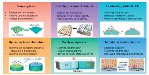
Designing suitable host structures is an effective strategy for improving the stability of AMAs [54]. A well-designed host mitigates volume expansion during deposition and stripping of the metal, thereby stabilizing the SEI. It confines the alkali metals within its pores, limiting direct exposure to the electrolyte and reducing active material and electrolyte loss due to side reactions. Moreover, hosts with a high specific surface area lower local current density and suppress dendrite formation [55]. An ideal host material should exhibit (1) a porous architecture with a high specific surface area to accommodate the metal and reduce the current density; (2) electrochemical stability throughout cycling; and (3) good compatibility with both the electrode and electrolyte to minimize side reactions [56].
Designing appropriate current collectors for AMBs can reduce the local current density and achieve the uniform distribution of alkali metal ion flux [57]. The ideal AMA current collector should have high electronic conductivity, a large specific surface area, and excellent mechanical stability, which can adjust the ion distribution, promote the uniform nucleation and growth of alkali metals, and prevent dendrite formation. For example, a three-dimensional current collector with a gradient distribution of alkali metal affinity can accommodate large alkali metal deposits, suppress the top growth of dendrites, and improve the safety of the battery [58].
In the deposition and stripping processes of alkali metals, the huge volume expansion will cause the rupture of the fragile SEI. Constructing a stable artificial SEI can make the Li+ flux uniform and avoid the growth of dendrites [59,60]. An excellent artificial SEI should have good mechanical strength that can effectively inhibit dendrite growth. The artificial SEI should also have sufficient flexibility and good fracture resistance to adapt to the large change in the volume of the alkali metal during the cycle. The artificial SEI should have good compatibility with both the electrode and electrolyte, which can effectively inhibit the occurrence of side reactions. The artificial SEI should have excellent ionic conductivity to ensure that the alkali metal is uniformly deposited below the SEI layer. Lastly, the artificial SEI should have fast self-healing ability, repairing the cracks occurring during the cycle and ensuring the long-term stability of the AMB during the cycle.
The stability of AMAs can be significantly improved by reasonably adjusting the composition of the liquid electrolyte [61]. The methods for adjusting the electrolyte's composition include the modification of alkali metal salts, the selection of suitable solvents, and the introduction of multifunctional additives [62]. The optimized liquid electrolyte can not only enhance the stability of the SEI, but also promote the formation of uniform ion flux and electric field distribution on the surface of AMAs. In addition, this optimized electrolyte can effectively control the ion distribution, thus inhibiting the adverse side reactions between the alkali metal and the electrolyte, comprehensively improving the performance of AMAs [63].
Separator modification is of great significance for improving the performance of AMBs. Modification strategies include selecting separator materials with high ionic conductivity and chemical stability, treating the surface to enhance their hydrophilicity and electrolyte affinity, and improving the mechanical and thermal stability [55,63,64]. These modified separators build a stable ion transport path inside the battery, reduce the side reactions between the electrolyte and the electrode, and promote the balanced distribution of electric field and ion flux in the battery.
The application of solid electrolytes in AMBs can significantly improve the stability and safety of the batteries [22]. By introducing solid electrolytes, batteries can achieve a more stable SEI while ensuring uniform ion flux and electric field distribution on the surface of the AMAs [64,65]. In addition, the application of solid electrolytes effectively controls the distribution of ions inside the battery, thereby suppressing adverse side reactions between the alkali metals and electrolytes, thus comprehensively improving the performance of AMAs [66,67].
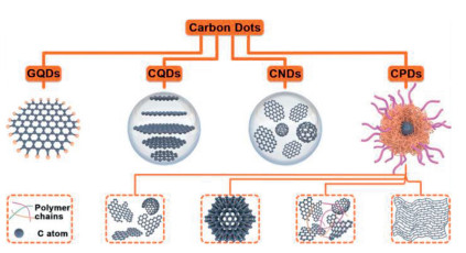
CDs are zero-dimensional carbon nanomaterials discovered in the 21st century [68]. CDs are usually composed of a carbon core and the amorphous shell. The carbon core is graphite or amorphous carbon, and an amorphous shell contains rich functional groups, polymer chains, defects, or doping elements [34]. As shown in Fig. 3, according to the carbon core structure, surface active groups, and physical and chemical properties of the shell, CDs can be roughly divided into four groups: GQDs, CQDs, carbon nanodots (CNDs) and carbonized polymer dots (CPDs) [34,36,37,68,69]. Among these, the carbon core of GQDs is composed of a small amount of graphene sheets (< 5 layers), with an obvious graphene lattice and chemical groups at the edges or interlayer defects, exhibiting quantum confinement effects; chemical groups are present at the edges and surfaces. Both CQDs and CNDs exhibit a similar spherical or quasi-spherical particle morphology, and there are chemical groups on the surface. However, the surface of CQDs has obvious lattice and chemical groups, showing a quantum confinement effect. The core of CNDs is composed of amorphous carbon, which lacks a lattice structure and has a high degree of carbonization. CPDs have a carbon–polymer hybrid skeleton and a large number of functional groups or polymer chains on the carbon core's surface. CPDs not only have the excellent optical properties of traditional CDs but also inherit the characteristics of polymers. They have unique characteristics such as a high oxygen/nitrogen content, excellent water solubility, and excellent photoluminescent quantum yield, which are attributed to the carbon–polymer hybrid structure and their characteristic photoluminescence mechanism [34,70].
CDs are renowned for their tunable photoluminescence (PL) properties, and the optical properties of CDs have been a subject of in-depth research over the past decade [33,70–72]. Although various CDs with different fluorescent properties have been developed, their PL mechanism has not yet been clearly elucidated [36,73]. So far, surface defects, quantum size effects, fluorescent groups, and the carbon core are considered to be the main sources of PL for CDs [36]. Furthermore, the PL intensity of CDs is related to many factors, such as their size and concentration, quantum yield, and carbon precursor. This means that the PL properties can be regulated by changing the preparation process. For instance, Hou and coworkers used surface passivation treatment and heteroatom doping methods to adjust the PL properties [34].
Another advantage is that, compared with traditional quantum dots based on toxic elements such as cadmium sulfide and cadmium selenide, CDs also show the advantages of nontoxicity and a low cost [37,74]. Therefore, CDs has been widely used in sensing, optoelectronics, biology, and other fields [72,75].
Many studies have shown that CDs have excellent electron donor/acceptor properties, which can accelerate electron conduction and improve the conductivity and stability of electrodes [76]. Meanwhile, there are usually some defects and functional groups on the surface of CDs, which often have high reactivity and strong adsorption and coordination ability, allowing them to capture some ions in the electrolyte and slow down the migration of these ions. Moreover, CDs have a large specific surface area and abundant surface functional groups (such as -COOH, -OH, -NH2), which are beneficial for providing abundant active sites, enhancing the wettability between the electrode and electrolyte, accelerating ion transport and increasing the kinetics of redox reactions on the electrode. The presence of functional groups enables CDs to exhibit good dispersibility in various electrolytes, making them a promising additive for modified liquid electrodes and solid electrolytes [34,36,37]. In view of the unique characteristics of CDs, research into CDNMs in AMBs is becoming more and more popular.
In 2004, Xu et al. discovered fluorescent CQDs for the first time in the process of purifying the products by electrophoresis. A large number of reports related to CDs have emerged since then [77]. According to current reports, the preparation methods of CDs can be divided into top-down methods and bottom-up methods [40,70,78], as shown in Fig. 4.
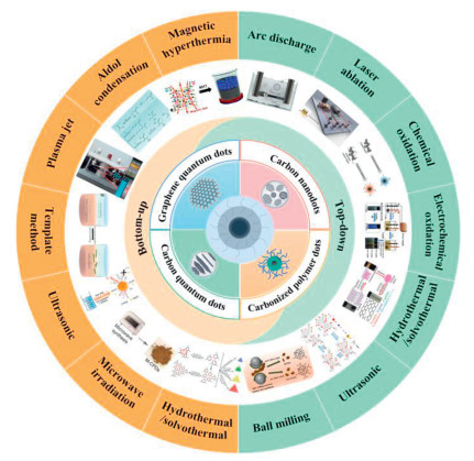
Top-down methods typically refer to the use of physical, chemical, or electrochemical methods to cut or disperse large-sized carbon materials such as graphite, carbon nanotubes, and carbon fibers into nanoscale carbon-based materials [33,79,80]. CDs prepared by a top-down method usually contain fewer sp3 hybrid carbon components and defective structures, which helps maintain the excellent conductivity of the carbon material. Common top-down methods include arc discharge [81,82], laser ablation [83,84], chemical oxidation [85,86], electrochemical oxidation [87,88], hydrothermal/solvothermal methods [89,90], ultrasonication [91,92], and ball milling [93,94]. Among these, the arc-discharge and laser ablation methods typically require sophisticated equipment and specialized techniques. Because of their complex processes, high costs [95,96], and issues such as low yield, abundant defects, and poorly controllable morphology, the practical application of these methods on an industrial scale is significantly hampered [78,97,98]. However, chemical oxidation, ultrasonication, electrochemical oxidation, hydrothermal/solvothermal methods, and ball milling are widely used in the preparation of CDs because of their advantages such as abundant raw materials, simple operation and easy large-scale production [78,97].
Arc discharge was the first method to discover fluorescent CDs. It is a method of reassembling the carbon atoms decomposed from a bulk carbon precursor through use of a plasma-driven anode electrode [74]. For example, Nooshin et al. synthesized a CD dispersion solution via arc discharge of two high-purity graphite electrodes in a deionized water medium. By replacing the graphite electrode with a titanium rod electrode in this solution, spherical TiO2/CDs nanoparticles with an average size of 27 nm were synthesized after arc discharge [81]. Meanwhile, Chao-Mujica and co-workers proposed a new method for synthesizing nanostructures based on submerged arc discharge, which improved the stability of arc discharge and thus increased the purity of the product. In subsequent work, as shown in Figs. 5a and b, they concentrated and purified the suspension obtained through submerged arc discharge in water, successfully synthesizing 1–5 nm CQDs, further verifying the simplicity, natural phase separation, and scalability of this method [82,99].
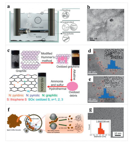
Furthermore, the hydrothermal/solvothermal method is one of the most widely used methods for synthesizing various CDs. The specific operation is to put the raw material into a closed container, with water or an organic solvent as the reaction medium, and react it at high temperature and pressure, which significantly accelerates the conversion and production speed of CDs [72,100]. As shown in Fig. 5c, Zhang et al. selected ammonia nitrogen and S powder as the source of N and S, and used graphene oxide as raw material to prepare strong blue luminous and water-soluble nitrogen and sulfur co-doped graphene quantum dots by a one-step hydrothermal method. Compared with N-GQDs, the prepared nitrogen and sulfur co-doped graphene quantum dots have brighter luminescence characteristics (Figs. 5d and e) [101].
In contrast to the abovementioned methods, ball milling offers a mechanochemical preparation route under ambient temperature and pressure conditions. It uses a high-energy ball mill, where the materials undergo physicochemical transformation through collision, friction, and the shearing forces exerted by the milling medium, thereby enabling chemical bond cleavage, particle refinement, and homogeneous mixing [102]. In order to simultaneously solve the problem of simultaneously achieving artificial functionalized CDs and carbonized carbon-rich precursors, Ge et al. prepared spherical CDs with an average size of 3.5 nm using the ball milling method using activated carbon and potassium carbonate as raw materials, and their surfaces were rich in oxygen-containing functional groups [94]. In addition, Jeong et al. found that wet ball milling of spent coffee grounds could prepare coffee ground-based CDs (CFCDs), as shown in Fig. 5f. Adding citric acid (CA) during the ball milling process endowed CFCDs with carboxylic acid groups. As shown in Fig. 5g, the average size of the prepared CA-CFCDs is 1.64 ± 0.04 nm, which is larger than that of CFCDs (1.59 ± 0.07 nm) as a result of the grafting effect of CA molecules. Furthermore, this method can also be extended to the synthesis of heteroatom-doped CDs, such as Jeong's preparation of N—CFCDs by adding o-phenylenediamine during ball milling. Because of the simple process of by ball milling, as well as its advantages of environmental protection and scalability, it has excellent application prospects [103].
In addition to the above, other methods such as laser ablation, chemical oxidation, electrochemical oxidation, and ultrasonication are also used to prepare CD-based nanomaterials [92,104–106]. Laser ablation is a single-step method of synthesizing CDs by irradiating the carbon target with a laser [72]. In the laser ablation process, local high pressure and high temperature can directly cut the target into residue-free nanoparticles, avoiding the introduction of impurities and eliminating pollution [33]. For example, Reyes prepared near-spherical amorphous CNDs between 5 nm and 20 nm by laser-ablating solid carbon targets using 1064, 532, and 355 nm laser pulses in a liquid environment. In addition, he tuned the emission wavelength of CNDs from the near-ultraviolet region to the green wavelength region by controlling the ablation time and the laser's wavelength [83].
The bottom-up methods are used to synthesize CDs by condensation, crosslinking, and carbonization of small molecules (small organic molecules, aromatic molecules) or polymer precursors through interactions between the precursors [71,97,107,108]. Compared with top-down methods, bottom-up methods, especially heteroatom doping, can better control the size and composition of the product by selectively selecting organic precursors and optimizing the polymerization/carbonization temperature [78,109–111]. Moreover, the synthesized CDs can easily inherit the dopant atoms and some functional groups of the organic precursors. At present, the common bottom-up methods for synthesizing CDs include hydrothermal/solvothermal treatment [112,113], microwave irradiation [52,114], ultrasonication [115,116], the template method [117,118], plasma jets [119,120] and other methods.The hydrothermal/solvothermal method is also widely used in bottom-up methods because of its simple operation, low cost, high efficiency, and environmental friendliness [40,95,107]. There have been many reports that CA has been used as a precursor system to prepare CDs. For example, as shown in Fig. 6a, Wang et al. synthesized M-CPDs and H—CPDs using CA and ethylenediamine as raw materials through microwave and hydrothermal synthesis, correspondingly [52]. Comparing Figs. 6b and c, it can be observed that the size of H—CPDs (2–4 nm) is smaller than that of M-CPDs (5–9 nm). Moreover, compared with M-CPDs synthesized by microwave method, the synthesis of H—CPDs is relatively mild, and H—CPDs exhibit richer lipophilic functional groups (pyridinic-N, pyrrolic-N, -COOH), so it can inhibit lithium dendrites more effectively. It effectively improves the Li+ transmission dynamics of stable LMBs, and promotes the practical application of CPDs in the field of energy storage.
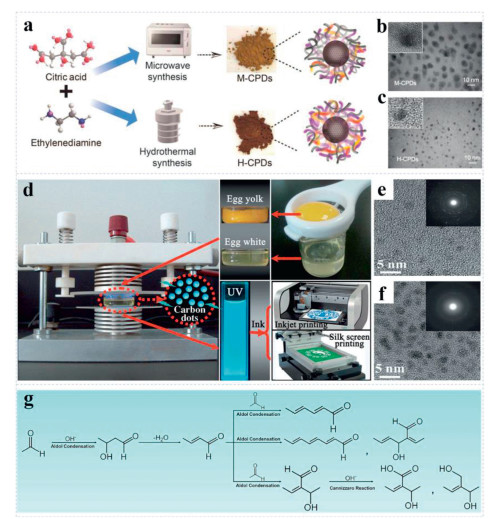
Moreover, plasma preparation is a method of using plasma technology to activate the carbon source's molecules in a high-temperature and high-energy environment so that they undergo chemical reaction to produce CDs. In this process, the high-energy electrons and ions generated by the plasma interact with the carbon sources molecules, triggering chemical reactions such as cracking, polymerization, and hydrogenation to form CDs with unique properties. For instance, Wang et al. used separated egg whites and yolks as carbon sources and placed them in the glass culture dish of a plasma generator [121]. CDpew and CDpey were rapidly synthesized by irradiating egg white or egg yolk samples, respectively, with plasma beams for 3 min, and their solutions exhibited bright blue fluorescence under ultraviolet light (Fig. 6d). From high-resolution transmission electron microscopy (TEM) images, it can be seen that both CDpew and CDpey exhibit uniform dispersion. However, the average particle size of CDpew is 2.15 nm, and the average particle size of CDpew is 3.39 nm (Figs. 6e and f). The difference in size is a result of the different carbon source components. In addition, because of the stable fluorescence characteristics of CDs and their good dispersibility in solvents, they have shown good application prospects in inkjet and silk-screen printing (Fig. 6d).
In addition, apart from the aforementioned bottom-up methods, aldol condensation polymerization method has been also used to synthesize CDs (Fig. 6g). Under the action of the base catalyst, the aldol alcohol reaction of acetone or aldehyde can form unsaturated ketones or aldehydes. Subsequently, the unsaturated aldehydes can undergo a series of substitution and condensation reactions to form many chains and tiny carbon clusters. Polymer chains and small clusters containing different functional groups or branches then curl, intertwine, or carbonize, crosslinking to form the carbon nuclei of CDs [122]. For example, Li et al. synthesized kilogram-scale CDs in 2 h via an aldehyde–alcohol reaction using acetaldehyde and sodium hydroxide as the raw materials. It can be seen that this method has great potential in large-scale synthesis. In addition, because of the diversity of raw materials, aldol condensation polymerization can readily be used to design various structures and heteroatom-doped CDs [102]. On the basis of several experiments, Li et al. successfully synthesized N-doped and N, S co-doped CDs by adding carbonate amine or cysteine to the reaction substrate [122].
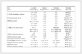
In recent years, CDs have been successfully applied for modifying solid electrolytes, optimizing liquid electrolytes, designing lithium salts, and constructing SEIs for AMBs [25,63,123]. Their excellent application advantages are mainly reflected in the following aspects. First, CDs are small size, have a large specific surface area, and have abundant surface functional groups that can be uniformly dispersed in various electrolytes. By utilizing the interaction between the surface functional groups and alkali metals, the transport kinetics of alkali metal ions can be improved [124]. Second, CDs can form anion clusters and restrict anions' movements, which is expected to achieve high ion transfer values and reduce the risk of dendritic growth [125]. Third, by leveraging the affinity of surface functional groups, an SEI layer constructed from CDs can exhibit good ion conductivity and electrical insulation, which can induce a more uniform deposition and stripping process of alkali metals. A summary of the methods of synthesis and their battery performance are provided in Table 1.
 DownLoad:
CSV
DownLoad:
CSV
| Material | Synthesis methods | Voltage hysteresis (mV) |
Cycling lifespan (mA/cm2, mAh/cm2) |
Ref. |
| Lithium metal batteries | ||||
| Introducing solid electrolytes | ||||
| GOQDs | Chemical oxidation and ultrasonication | 130 | 300 h (0.5, 1.5) | [126] |
| CQDs | Aldol condensation and polymerization | 30 | 60 h (0.1, 0.05) | [24] |
| NS-CDs | Aldol condensation and polymerization | 40 | 1200 h (0.5, 0.5) | [27] |
| PLSSCQD | Pyrolysis | - | - | [26] |
| CDs | solvothermal | 100 | 1400 h (0.5, 0.5) | [112] |
| CD-Li | Aldol condensation and polymerization | 30 | 900 h (0.2, 0.2) | [28] |
| GQDs | Hydrothermal | 50 | 900 h (0.1, 0.1) | [123] |
| FCDs | Aldol condensation and polymerization | 28 | 1000 h (0.4, -) | [150] |
| fCQDs | Microwave irradiation | - | - | [29] |
| NSFCDs | Aldol condensation and polymerization | 76 | 4000 h (0.1, 0.1) | [23] |
| CDs | Aldol condensation and polymerization | 50 | 1300 h (0.1, 0.1) | [76] |
| NSFCDs | Aldol condensation and polymerization | 20 | 1200 h (0.1, -) | [149] |
| CDs | Hydrothermal | 6 | 1000 h (1, -) | [134] |
| Optimizing liquid electrolyte | ||||
| U-CD | Solvothermal treatment | 150 | 250 h (0.1, 0.1) | [127] |
| Li-GQD | Chemical oxidation and ultrasonication | 24.9 | 200 h (0.1, 0.1) | [136] |
| H-CPDs | Hydrothermal treatment | 4.5 | 3100 h (0.1, 0.5) | [52] |
| Others | ||||
| N-GQDs | Hydrothermal treatment | 12.6 | 9000 h (20, 1) | [39] |
| FCDs | Aldol condensation and polymerization | 50 | 3000 h (0.3, 0.15) | [25] |
| CQDs | Hydrothermal treatment | 30 | 2400 h (1, 1) | [51] |
| NCDs | Hydrothermal treatment | 20 | 5000 h (0.1, 0.05) | [141] |
| Sodium metal batteries | ||||
| Introducing solid electrolytes | ||||
| CQDs | Aldol condensation and polymerization | 90 | 60 h (0.1, 0.05) | [24] |
| Optimizing liquid electrolyte | ||||
| CDs | Aldol condensation and polymerization | 25 | 1200 h (1, 1) | [38] |
| NCQDs | Solvothermal treatment | - | 700 h (0.5, 0.5) | [144] |
| Potassium metal batteries | ||||
| Optimizing liquid electrolyte | ||||
| CDs | Ultrasonication | 150 | 1400 h (0.1, -) | [145] |
LMBs with a high specific energy have attracted widespread attention. However, the poor cycling stability, serious dendrite growth, and large volume expansion seriously restrict the further application and development of LMBs [44,67]. Typically, the strategies using CD-based nanomaterials in LMBs include Introducing solid electrolytes [24,26–28], 76,112,123,126], optimizing liquid electrolytes [52,127], host design [39], and constructing artificial SEIs.
The use of solid electrolytes instead of separators and liquid electrolytes can fundamentally alter the deposition behavior of Li+ [128,129]. Solid electrolytes have the advantages of nonflammability, good chemical and electrochemical stability, and high mechanical strength, which can greatly improve the safety of the battery and improve the stability between the electrolyte and the anode [13]. In solid electrolyte, solid polymer electrolytes have good machining properties and low interface impedance, and can form good interfacial contact with anode, and thus has been favored by researchers. However, because of the influence of the crystal phase, the movement ability of the polymer segment of solid polymer electrolytes is poor, resulting in a decrease in ionic conductivity at room temperature [64,112]. To solve this problem, introducing inorganic fillers to construct composite solid electrolytes is an effective strategy, as it not only reduces the crystallinity and enhances chain segments' movement, but also promotes the dissociation of lithium salt and provides multi-channel ion transport pathways [66,67]. Research has shown that the smaller the size of a nanoscale filler (such as SiO2 and TiO2), the more favorable it is for ion transport, but the problem of easy aggregation limits their application. CDs can be uniformly dispersed in solid polymer electrolytes because of their rich surface functional groups, effectively solving this problem [24]. Below, we summarize the application of CDs in solid electrolytes, looking at solid-state electrolytes and gel electrolytes. The main analysis focuses on the mechanism of action of conventional CDs and functionalized CDs in solid electrolytes. The application advantages of CDs in gel electrolytes are also discussed.
The application of CDs in solid-state batteries has received widespread attention [130]. For instance, Hou's research group has made great contributions to the study of modifying PEO-based solid electrolytes with CDs. they used an acetaldehyde solution and bis(trifluoromethane)sulfonimide lithium salt as the raw materials and sodium hydroxide as the catalyst [28]. After the aldol reaction, a specific lithium-ion conductor based on CDs (CD-Li) was prepared (Fig. 7a). The prepared CD-Li has a distinct structure: The center is a CD, and the surface of the CD is rich in short polymer chains. As can be seen from the TEM image in Fig. 7b, the average size of the prepared CD-Li is 3.64 nm, which is very small compared with traditional fillers. Subsequently, they applied CDs to PEO-based electrolytes and found that the electrolyte exhibited excellent performance. As a result, at a current density of 0.2 mA/cm2, the composite symmetric electrolyte-based lithium battery exhibited a lower polarization voltage and always maintained stable performance during the 900 h cycle (Fig. 7c). The PEO/CD-Li composite electrolyte-based NCM523/Li battery showed a much higher capacity retention rate than the PEO/LiClO4 electrolyte at 0.2 C (Fig. 7d). The excellent electrochemical performance could be attributed to the strong electronegativity of F atoms in CD-Li, which induced the formation of a LiF-rich SEI layer in situ at the electrolyte–electrolyte interface, thereby improving its stability and ensuring the rapid transport of the ions on it.
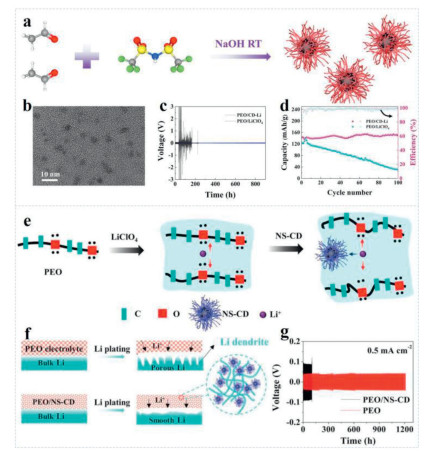
Moreover, the effect of functionalized CDs on the migration of lithium ions in the electrolyte has also been studied [27]. Xu and his coworkers have found that doping with heteroatoms can effectively alter the chemical activity of CDs. As shown in Fig. 7e, the addition of nitrogen/sulfur co-doped CDs (NS-CDs) in a composite electrolyte can affect the interaction between the PEO chain and Li+ [27]. 7Li NMR spectra reveal that the introduction of NS-CD can improve the proportion of mobile Li+ by 33.9% in the left peak. As the higher proportion of left peak indicates more mobile Li+, ionic conductivity of the composite electrolytes was increased correspondingly. Moreover, the addition of NS-CDs to the composite electrolyte can also make the Li+ flux more uniform and achieve uniform deposition and stripping processes of lithium metal (Fig. 7f). Therefore, the symmetric PEO/NS-CD-based Li battery exhibits excellent cycling performance, and the Li|PEO/NS-CD|Li battery remains stable at a current density of 0.5 mA/cm2 for more than 1200 h without short circuiting (Fig. 7g). These improved electrochemical properties could be attributed to the edge-nitrogen/sulfur in NS-CDs, which have a certain ability to adsorb Li+ and can weaken the interaction between the PEO chain and Li+. At the same time, Liu et al. compared -NH modified GQDs and -OH modified GQDs, finding that the combination of Li+ with the -NH and -OH groups can greatly reduce the binding energy of Li+ and the PEO chain, thus promoting Li+ transmission [123]. Specifically, the -NH groups exhibit stronger Lewis base interactions with Li+ than -OH groups, which facilitates Li+ desolvation from the PEO matrix. Therefore, GQD-NH demonstrates enhanced interfacial compatibility, promoting the formation of a stable and thin SEI layer and effectively suppressing lithium dendrite growth during repeated cycling.
Although the addition of CDs to the SPEs can significantly improve the lithium-ion transfer number, the ionic conductivity of the electrolyte in solid-state LMBs is still unsatisfactory, and it is difficult to reach the mS/cm level. In comparison, Gel polymer electrolytes, with simple manufacturing processes and high ionic conductivity, are considered to be one of the most competitive candidates for solving this difficulty [131–133]. Therefore, by combining the advantages of gel polymer electrolytes and CDs, it is expected to achieve CSEs with both a high ion conductivity and high ion transfer number. For example, Liu et al. innovatively utilized the quantum size effect of CDs and the abundant functional groups on their surfaces to form a physical crosslinked network with poly(1,3-dioxolane) molecular chains through hydrogen bonding [134]. The addition of CDs significantly disrupted the original crystalline structure of poly(1,3-dioxolane), forming a large number of amorphous regions, while constructing three-dimensional continuous ion transport channels through hydrogen bonding interactions (Fig. 8a). Molecular dynamic simulations further revealed that in the cross-linked gel polymer electrolytes (CDPE) system, the hydrogen bond crosslinking between CDs and molecular chains of poly(1,3-dioxolane) significantly shortened the interchain transport pathway of lithium ions and reduced the ion migration energy barrier (Fig. 8b). This structural advantage enabled CDPE to achieve a high ion conductivity of 3.20 mS/cm at 30 ℃. The Tafel test showed that the symmetrical battery based on CDPE exhibited a high exchange current density of 6.227 mA/cm2, confirming its excellent interfacial lithium-ion transport kinetics (Fig. 8c). The Li|CDPE|LiFePO4 (LFP) battery maintained a capacity retention rate of 92% after 2000 cycles at a rate of 2.0 C (Fig. 8d), demonstrating excellent long cycling stability. The electrolyte's superiority is attributed to the hydrogen bond crosslinking network constructed by the CDs, which significantly improves ion transport efficiency, whereas the stable interface layer induced effectively inhibits lithium dendrite growth.
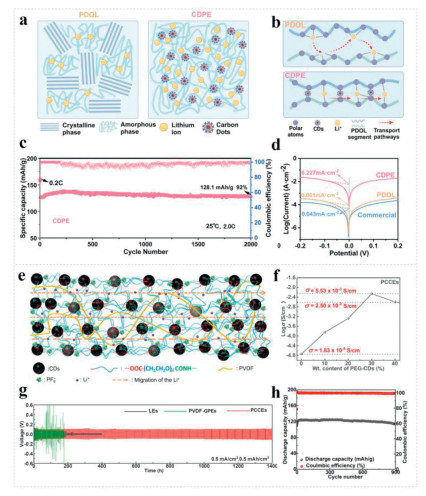
In addition, a novel gel electrolyte system was innovatively constructed through the interaction between functionalized CDs and a polymer matrix. Huang et al. innovatively proposed crosslinking CDs with PEG to form a PEG-CD network and then making a new type of PEG-CD composite electrolyte (PCCEs) by adding an appropriate amount of polyvinylidene fluoride and some liquid electrolytes (LEs) (Fig. 8e) [112]. The PCCEs not only have a high ion transference number of 0.71, but also show a high ionic conductivity of 5.5 mS/cm (Fig. 8f). Moreover, the large-sized anions in PCCEs are affected by volume effects, making it difficult for them to move in dense polymer networks, whereas the movement of the smaller Li+ is not affected, resulting in an increase in the ion transference number (tLi+). As a consequence, symmetric batteries using PCCEs exhibit the best cycling stability at a current density of 0.5 mA/cm2, with a stable cycling life of 1400 h without short circuits (Fig. 8g). In addition, the LiFePO4/PCCEs/Li battery exhibits a stable capacity curve at 2 C with a Coulombic efficiency of up to 99.37% after 900 cycles (Fig. 8h). The excellent ion conductivity could be attributed to the uniformly dispersed CDs that physically disrupt polymer chain packing, reducing PVDF crystallinity and creating amorphous regions for ion transport. Moreover, abundant polar groups on CDs can provide Lewis acid–base interaction sites that promote lithium salt dissociation and construct continuous ion-conducting pathways along polymer–CD interfaces, its higher tLi+ is attributed to the H-F hydrogen bond between either PF6− and polyvinylidene fluoride chains or PEG-CDs, limiting the movement of anions.
In addition, the uncontrolled dendrite growth of alkali metals during charging and discharging is closely related to the chemical composition of the electrolyte [62]. The use of electrolyte additives is considered to be one of the most effective ways to solve these problems, because this strategy is simple to operate, has a good effect on the inhibition of dendrites, and is feasible for large-scale application. By adjusting the deposition form of alkali metal and slowing down the corrosion of alkali metal, it can significantly improve the stability of the interface between the metal anode and the electrolyte and its cycling efficiency [128,135]. There have been some articles reporting the use of CDs as electrolyte additives to improve batteries' performance. CDs are small (nanometer scale) and rich in functional groups carbon and nitrogen on the surface, and they can be easily dispersed in the electrolyte and achieve uniform deposition of metal cations [52]. For instance, Li and coworkers employed microwave and hydrothermal methods to prepare M-CPDs and H—CPDs, respectively [52]. The H—CPDs provided more binding sites for Li+, inducing the uniform nucleation of Li (Fig. 9a). Correspondingly, as shown in Figs. 9b and c, the surface of the Cu foil and the Li sheet after cycling exhibited smooth morphological features. When a symmetric battery with H—CPDs as an additive was tested under the testing conditions of 0.1 mA/cm2 and 0.5 mAh/cm2, it exhibited the stable performance for 4000 h and an ultra-low overpotential of ~4.5 mV after a cycling for 3100 h (Fig. 9d). Li|LiFePO4 full cells assembled with H—CPDs showed a superior capacity retention rate, namely 93.8% after 200 cycles at 1 C (Fig. 9e). These excellent performances are attributed to the high content of pyrrolic N (53.94%) and pyridinic N (18.01%) in H—CPDs. Owing to the existence of extra electrons on pyridinic-N and pyrrolic-N, more lithiophilic sites were obtained for combining with Li+, thereby significantly reducing the energy barriers of the nucleation process. Thus, the initial nucleation overpotential decreases from 206 mV in the electrolyte without CPDs to 78 mV in the presence of H—CPDs. In addition, the Li 1s XPS spectra shows that the peak strength of LiF is significantly higher in H—CPDs-containing electrolyte than that without CPDs, indicating its content is the most in H—CPD. This LiF-rich interphase are favorable to the formation of stable SEI.
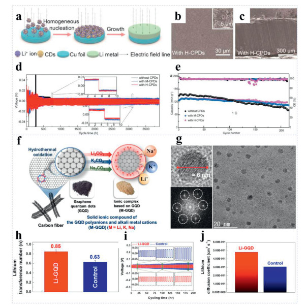
Furthermore, CDs can be used as traditional electrolyte additives and in the development of new types of alkali metal salts to provide high ion conductivity, high ion migration numbers, excellent chemical stability, and thermal stability [61,136–138]. As shown in Fig. 9f, Lim et al. prepared GQDs using carbon nanofibers as the raw materials by hydrothermal oxidation, and then placed them in a solution of the metal precursors (Li2CO3, K2CO3, and Na2CO3) for processing [136]. In this process, carboxylate anions (COO−) on the GQDs' surface interact with alkali metal cations through electrostatic interaction. Finally, M-GQDs (where M means Li+, Na+, or K+ alkali metal cations) were obtained. Taking the lithium salt as an example, the Li-GQDs presented a circular or elliptical structure, with a sp2 conjugated carbon network at its core and an amorphous structure at its edges (Fig. 9g). The Li-GQDs electrolyte exhibited a high tLi+ value (Fig. 9h), which reduced the ion concentration gradient between the electrode and electrolyte, thereby reducing the polarization of the battery [139,140]. During the cycling process of symmetrical Li/Li cells, the battery with the Li-GQD electrolyte exhibited more stable cycling performance and a lower polarization voltage (Fig. 9i). Moreover, the Li+ diffusion coefficient of the Li-GQD electrolyte was much higher than that of the control group (Fig. 9j). The excellent performance was ascribed that GQD ionic complexes can provide highly abundant free metal cations with highly stable GQD polyanions. Specifically, the binding free energy of the GQD polyanions showed a strong repulsive peak of ~9.5 kcal/mol, whereas that of PF6− anions is as low as 2 kcal/mol. Because of the high free energy barrier, the undesirable coagulation of the GQD polyanions mediated by Li+ cations would be easily avoided. As a result, ionic complexes based on the GQD polyanion are expected to provide free Li+ cations and the GQD polyanions because they are stably distributed in the dissolved state.
In addition to the above strategies, carbon dot-based materials can also be applied to host design [39], artificial SEI construction [51], and other aspects [25,141] to improve the performance of lithium metal batteries.
To effectively address the uncontrollable volume changes of lithium metal during cycling and achieve uniform deposition and stripping on the anode electrode surface, a feasible strategy is to incorporate carbon dot materials into the host structure design. For instance, Ponraj and coworkers prepared N-GQDs using hemp fibers as raw materials by a hydrothermal method. The prepared N-GQDs had carbonyl, carboxyl, hydroxyl, and N-containing lithiophilic functional groups [39]. Moreover, as shown in Fig. 10a, Kim et al. immersed Cu foam into an aqueous solution of N-GQDs and successfully seed-coated N-GQDs on Cu foam after vacuum drying, which was the first application of CDs in the construction of host in LMBs. The host formed by an N-GQD coating can uniformly deposit Li and exhibits excellent dendrite suppression ability. Specifically, N-GQD@Cu|N-GQD@Cu symmetric cells exhibit ultra-long cycling stability even at high current densities of 30 mA/cm2. In addition, under the action of the host design with mechanical robustness, the growth of dendrites is suppressed, thereby improving the cycling stability of the battery (Fig. 10b). Consequently, the fully assembled pre-lithiated N-GQD@Cu|LFP battery showed excellent cycling stability at 1.0 C, with 80% capacity retention rate after 500 cycles (Fig. 10c). This outstanding performance is attributed to the following aspects. The pyridinic-N functional group on the surface of N-GQD can attract Li+ through Lewis acid-base interactions and induce the uniform deposition of Li+, whereas the electron-rich carbonyl groups of N-GQD can attract Li+ in the electrolyte through electrostatic interactions, inducing a uniform lithium-ion flux.
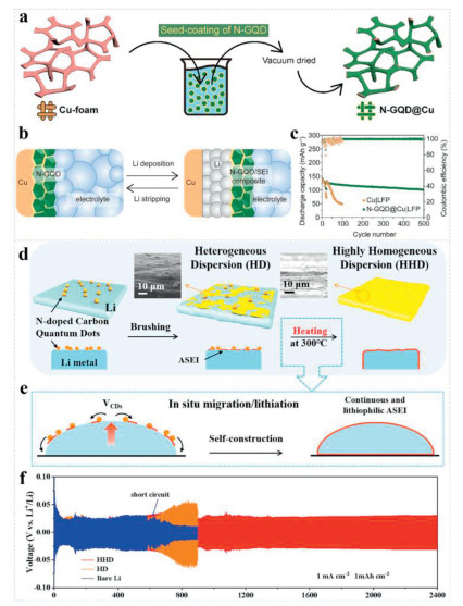
Furthermore, using carbon dots to construct stable artificial solid electrolyte interfaces is also a feasible solution to achieve dendrite free lithium metal anode. For example, Liu et al. proposed a method for uniformly dispersing and in-situ lithiation of N-doped CQDs based on phase transition driving and thermodynamic diffusion for constructing artificial solid electrolyte interfaces (Fig. 10d) [51]. During the heating process, the phase transition fluctuations of liquid lithium metal and the surface tension gradient (Marangoni effect) jointly promote the dynamic diffusion of CQDs from the initial aggregation zone to the entire surface, achieving a transition from "point contact" to "surface contact", greatly improving the utilization efficiency of CQDs (Fig. 10e). The symmetrical battery was stably cycled for 2400 h at 1 mA/cm2, with a polarization voltage of less than 30 mV, and its performance is significantly better than traditional heterogeneous dispersion (HD) electrodes and bare lithium electrodes (Fig. 10f). This outstanding performance is attributed to the continuous and dense SEI layer formed, which is rich in Li3N and LiCx. It significantly reduces the activation energy of lithium ion migration and prevents exposure of the lithium metal surface and further side reactions, effectively suppressing dendrite growth.
SMBs and potassium metal batteries (PMBs) have emerged as promising alternatives to LMBs, offering significant advantages in terms of cost and safety [9,142,143]. However, they still face considerable challenges related to energy density and cycling stability, and currently remain largely in the laboratory-scale research or early development stages. In recent years, the application of CDs in SMBs and PMBs has garnered increasing attention. Research efforts have primarily focused on modifying solid electrolytes [24] and optimizing liquid electrolytes [38].
Similar to their application in lithium metal batteries, the addition of CDs also demonstrates significant advantages in the solid electrolytes of SMBs. By incorporating CDs to reduce the crystallinity of the polymer matrix, the performance of sodium batteries can be enhanced. For instance, Hou's group prepared CQDs with an average diameter of 2.0–3.0 nm via the aldol condensation method, and the CQDS showed good dispersibility [24], as shown in Fig. 11b. The addition of CQDs to a PEO-based solid electrolyte can greatly improve the electrochemical performance of the electrolyte and the cycling performance of the battery. As shown in Fig. 11c, the initial discharge specific capacity of the PEO/CQD-Na-based battery is 101.5 mAh/g, then 89.4 mAh/g after 100 cycles at 1 C, which is much higher than that of a PEO—Na-based battery. In addition, a solid-state Na battery with PEO/CQD-Na electrolytes exhibited a higher specific capacity and more stable Coulombic efficiency at different rates (Fig. 11d). Specifically, FTIR measurements show that the dissociation ratio of NaClO4 increases from 86.1% in the pristine PEO electrolyte to 97.9% for the PEO/CQDs nanocomposite polymer electrolytes, indicating that oxygen functional groups on the surface of CQDs can interact strongly with NaClO4 salts and then release more free ions. Meanwhile, as the weight ratio of LiClO4/CQDs sample increases, the zeta potential decreases from positive to negative. The zeta potential is around zero at a weight ratio of 1.93, which reveals adsorption of ClO4− anions at the surface of CQDs by positively charged Lewis acid sites. These excellent electrochemical properties could be attributed to the strong Lewis acid–base interaction of CQD, NaClO4, and PEO, which can disrupt the orderly packing of PEO chains, reducing polymer crystallinity and increasing amorphous regions for ion transport, as well as enhance the dissociation of Na salts and the adsorption of ClO4− anions (Fig. 11a) [24].
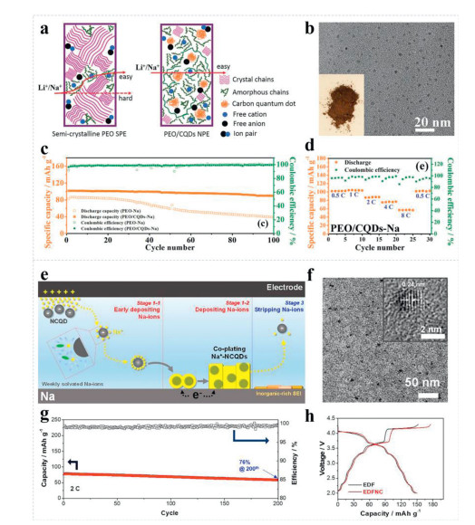
In order to explore the versatility of CDs as electrolyte additives in different AMBs systems. Lee et al. prepared nitrogen doped CQDs (NCQDs) using CA and urea as carbon precursors via a hydrothermal method, and optimized them as electrolyte additives [144]. Research has shown that when NCQDs are introduced into an electrolyte, these negatively charged NCQDs interact strongly with Na+, not only changing the solvation environment and promoting the dissociation of Na salt, but also weakening the binding force between the Na+ and the solvent's molecules, resulting in a more uniform deposition on the Na metal anode surface (Fig. 11e). High-resolution TEM characterization shows that the NCQDs are in a monodisperse state, with a lattice spacing of 0.24 nm corresponding to the [1120] crystal plane of the sp2 cluster (Fig. 11f). At a high current density of 2 C, the battery using the designed electrolyte by NCQD (EDFNC) electrolyte exhibits excellent cycling stability, with a capacity retention rate of 76% after 200 cycles (Fig. 11g). In addition, the full battery was cycled within a wide voltage window of 2.0–4.3 V, verifying the excellent performance of the EDFNC electrolyte at high operating voltages (Fig. 11h). The excellent electrochemical performance is attributed to the dual effect of NCQDs. The pyridine and pyrrole nitrogen functional groups on NCQDs endow the surface with negative charges and can generate strong interactions with sodium ions, thereby reducing the energy barrier of extracting Na from the surface of Na. In addition, NCQDs contribute to the formation of a robust SEI layer rich in inorganic components such as Na2O, NaF, Na-phosphate and N-containing species, facilitating the migration of Na-ions within the electrolyte and enabling dendrite-free Na plating.
Recently, in order to address the issues of dendrite growth and side reactions in potassium metal negative electrodes, Liu et al. introduced multifunctional CDs as additives in the electrolyte [145]. Because of the presence of electronegative functional groups on the surface of CDs, they can adsorb potassium ions and achieve uniform deposition, enabling symmetric potassium|potassium batteries to operate stably for over 1000 h under a current density of 0.1 mA/cm2, with a critical current density of 5.5 mA/cm2. This study provides a simple and effective solution for the application of high rate, long-life PMBs. However, it should be acknowledged that extending carbon dot strategies from lithium to sodium and potassium metal systems remains faces significant challenges [41]. These primarily stem from the larger ionic radii of Na+ and K+, which lead to sluggish kinetics, severe volume expansion, and unstable SEI layer formation [146,147]. In addition, the interfacial chemistry between carbon dots and sodium/potassium metals is not yet well understood, and the effectiveness of carbon dots in regulating nucleation behavior to suppress dendrite growth in these systems lacks systematic validation [148]. Therefore, the practical application of carbon dots in sodium and potassium metal batteries still requires more fundamental investigation.
As discussed in 5.1 The application of CDNMs in LMBs, 5.2 The application of CDNMs in sodium and potassium metal batteries, the application of CDNMs in AMBs have been reviewed, including introducing solid electrolyte, optimizing liquid electrolyte, and constructing artificial SEI. The incorporation of CDs can optimize ion transport, reconstruct interfacial structure and suppress dendrite growth to improve electrochemical performance of AMBs. In terms of their effectiveness for dendrite suppression, interfacial stabilization, and electrochemical performance, different types of CDs show different working mechanisms. (1) In the aspect of dendrite suppression, GQDs could promote uniform alkali metal deposition due to their higher density of lithiophilic heteroatom sites [39,52]. For example, nitrogen-rich GQDs (N-GQDs) was coated on 3D Cu foam by Ponraj and coworkers, and the nucleation overpotential of the Li‖Cu half-cell was reduced to 3 mV, compared to 45 mV on bare Cu, which could be ascribed that pyridinic‑N can serve as Lewis base sites to attract Li+. The facile nucleation of Li+ ions suggests that the N-GQD coating played a crucial role in improving the electrolyte wettability and lithiophilic characteristics, which could facilitate dendrite-free Li deposition [39]. Similarly, the introduction of CPDs into electrolyte for LMBs also could promote the uniform transfer and deposition of Li without the formation of Li dendrites, which is ascribed that more lithiophilic sites were obtained for combining with Li+ due to high contents of pyrrolic-N (53.94%) and pyridinic-N (18.01%) in CPDs [52]. (2) In terms of interfacial stabilization, the interfacial stabilization is largely dependent on the SEI composition, and the introduction of carbon dots could facilitate the formation of SEI with enhance mechanical stability [39,51]. For example, N-doped CQDs were used to construct an artificial SEI protection layer on molten Li liquid metal. The uniform dispersion of N-doped CQDs, along with the product layers of LiCx and Li3N produced by the in situ lithiation reaction uniformly covers the Li metal surface, forming a dense and protective interface layer, which effectively prevent the exposure of the pristine Li surface and further side reactions [51]. Moreover, CPDs were incorporated into a gel polymer electrolyte by Liu et al. via supramolecular physical crosslinking. The presence of CDs facilitated the reductive decomposition of FEC while simultaneously inhibiting the further decomposition of Li2CO3 into LiF. The resulting Li2CO3-rich CD-SEI facilitates uniform Li+ nucleation on the lithium metal surface, and improving the cycling performance of the lithium metal anode [134]. (3) In the aspect of their effectiveness for electrochemical performance, the introduction of different types of CDs exhibit distinct advantages in enhancing the AMBs' electrochemical performance. For instance, Ma et al. introduced carbon quantum dots with diameters in the 2.0–3.0 nm range, into the PEO matrix to form nanocomposite polymer electrolytes [24]. The prepared PEO/CQDs‑Li composite electrolyte can exhibit a high ionic conductivity of 1.39 × 10⁻⁴ S/cm and a high lithium transference number of 0.48 at room temperature, because the highly dispersed CQDs with oxygen functional groups that can effectively promote dissociation of LiClO4 salts and adsorption of ClO4− anions, and increase the amorphicity of PEO matrix [24]. Furthermore, a new class of ionic compounds composed of GQD polyanions and alkali metal cations was synthesized by Lim's group. The Li‑GQD electrolyte solution offers a wide electrochemical window of −0.2~5 V, because the carbonized structure of GQD can provide enough material durability to withstand harsh electrochemical environments when dissociated in a solvent to become polyanions [136].
In addition to the above discussion, the resulting electrochemical performance of different types carbon dots is also influenced by their various synthesis methods and characteristics. As summarized in Table 1, a clear correlation emerges between synthesis method, resulting CDs properties, and electrochemical performance: Aldol condensation tends to yield CDs with tailored heteroatom doping and well-defined functional groups (e.g., NS-CDs, FCDs), which consistently deliver low voltage hysteresis (20–50 mV) and prolonged cycling lifespans (up to 4000 h) [23,27,149,150]. Hydrothermal synthesis produces CDs with tunable nitrogen configurations that directly impact lithiophilicity and SEI stability [39,52]. In contrast, CDs with limited functionalization or amorphous carbon cores show inferior performance [127]. These correlations underscore that the rational design of CDs enables precise control over their physicochemical properties, thereby optimizing their effectiveness in dendrite suppression, interfacial stabilization, and overall electrochemical performance in alkali metal batteries.
In conclusion, this review examines the research progress on CDNMs in AMBs. We first summarize the structure and properties of CDs, then systematically introduce their preparation methods, including top-down and bottom-up approaches and comparing the advantages and disadvantages of each technique. Among these, hydrothermal or solvothermal synthesis is the method most commonly employed, whereas aldol condensation polymerization finds broader application in AMBs. Furthermore, the electrochemical enhancement mechanisms of CDNMs in AMBs are analyzed in detail through three modification strategies: as solid electrolyte modifiers, liquid electrolyte additives, and components in novel lithium salts and artificial SEIs. Among various carbon dot-based strategies, CD-based gel electrolytes are considered the promising because it can regulate the ion transport mechanism by forming a dynamic cross-linking network with the polymer chain, and build a SEI rich in beneficial components, transforming CDs from passive additives into active core components for next-generation alkali metal batteries. The superior performance of CD-based AMBs can be attributed to the following aspects. (1) CDs have a small size, high specific surface area, stable physicochemical properties, and abundant surface functional groups, enabling uniform and stable dispersion in both liquid and solid electrolytes while mitigating the agglomeration issues commonly seen with conventional nanofillers. (2) Their surface functional groups (e.g., pyridinic-N, carboxyl, hydroxyl) facilitate dissociation of the electrolyte salts and cation desolvation, thereby accelerating ion transport. (3) CDNMs can serve as large polyanionic clusters, significantly increasing the ion transference number and contributing to dendrite-free metal anodes. (4) CDNMs improve electrode–electrolyte compatibility and promote uniform cation nucleation and deposition when incorporated into SEI layers, leading to robust interphases that suppress dendrite growth. Therefore, the use of CDNMs can significantly improve the cycling performance of AMBs. Although CDNMs have made some significant progress, there are still many challenges to be solved, and researchers should pay more attention to the following aspects to promote their practical application (Fig. 12).
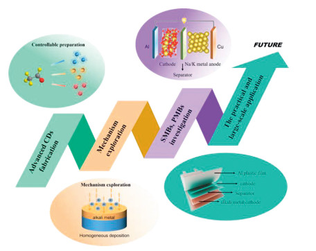
(1) Fabrication of advanced CDs. CDs for AMBs are currently predominantly synthesized via hydrothermal/solvothermal methods, owing to their simplicity in terms of equipment requirements and adaptability to diverse carbon precursors. These methods enable the tuning of CDs' physicochemical properties (e.g., size, defect density, doped elements, and surface functional groups), which directly govern electrochemical behaviors such as metal ion adsorption, ion transport kinetics, and interface stability in AMBs. Consequently, research on synthesizing CDs has expanded to other routes, including microwave-assisted synthesis, solid-phase pyrolysis, and electrochemical exfoliation. However, most existing methods suffer from inherent limitations: hydrothermal/solvothermal processes involve cumbersome post-synthesis purification and long reaction cycles, whereas microwave-assisted synthesis remains confined to laboratory-scale batch reactions with low yields. Solid-phase pyrolysis, though solvent-free, frequently produces CDs with a broad size distribution and uncontrollable surface functional groups. These issues collectively hinder the large-scale industrial production of CDs.
To address these challenges, future efforts should focus on developing potential process engineering approaches. For instance, introducing biomass feedstocks such as lignin and chitosan into mechanochemical methods like ball milling enables a solvent-free, low-cost route for large-scale production. Optimizing continuous-flow microwave reactors can shorten reaction cycles and ensure uniform carbon dot sizes. Additionally, precise control over the surface chemistry of carbon dots is essential, and template-directed synthesis can be used to customize their defect structures and doping element configurations. Beyond simple doping, future research should prioritize targeted design, such as co-doping with elements like nitrogen, sulfur, and phosphorus to generate synergistic effects, enhance lithiophilicity or catalytic activity, and lay the foundation for industrial applications of carbon dots in alkali metal batteries.
(2) Exploration of the mechanisms. Despite the proven efficacy of CDs in enhancing AMBs' performance, their underlying mechanisms of action remain insufficiently elucidated. Key knowledge gaps include the specific pathways by which CD surface functional groups inhibit metal dendrite growth, for example whether it involves electrostatic repulsion, chemical adsorption, or SEI film regulation; the synergistic effects of multi-component CDs such as N/P co-doped CDs on ion transport and interface stability; and the dynamic evolution of CDs during long-term cycling, particularly regarding potential structural degradation or migration. These ambiguities limit rational design of high-performance CD-based materials for AMBs.
To address these gaps, a combination of advanced characterization techniques and theoretical simulations is essential. In situ characterization tools should be fully utilized: In situ TEM can directly observe the dynamic interaction between CDNMs and metal dendrites during charge–discharge cycles. In situ X-ray photoelectron spectroscopy enables real-time analysis of changes in the SEI films composition mediated by CDNMs. In situ Raman spectroscopy can track structural evolution of CDs, such as defect healing or functional group loss. Complementarily, theoretical simulations can offer profound atomic- and mesoscale insights into the behavior of CDs in battery systems. Density functional theory (DFT) calculations are capable of quantifying the adsorption energy between CDs and metal ions, as well as the ion diffusion energy barriers within CD-modified electrolytes. Molecular dynamics (MD) simulations can elucidate the ion transport mechanisms and spatial distribution of Li+ or Na+ in CD-containing electrolytes. At a larger scale, COMSOL-based multiphysics modeling can reveal how the distribution of CDNMs influences current density uniformity and deposition morphology at the electrode level. Meanwhile, emerging artificial intelligence and machine learning techniques present new opportunities for constructing structure–performance databases of CDNMs, predicting optimal synthesis pathways, and designing CDNMs with targeted properties, thereby accelerating the development of high-performance CDNMs through mechanism-driven innovation.
(3) SMBs, PMBs, and other metal anodes applications. Current research on CD-based AMBs is heavily concentrated on LMBs, where CDNMs have been validated to improve performance via multiple mechanisms: Modifying electrolytes to inhibit Li dendrite growth, coating electrodes to enhance interface stability, or serving as conductive additives to boost electron transport. In contrast, research on SMBs remains scarce—existing reports are limited to using CDNMs to modify in Na metal anode interfaces, with insufficient exploration of CDNMs' effects on the deintercalation kinetics of Na+ in alloy-type or conversion-type anodes. Notably, there are fewer published studies on the use of CDNMs in PMBs.
To expand the scope of CDNMs' applications, future efforts should prioritize two key directions. First, research on CDNMs in sodium and potassium metal batteries needs deeper exploration. For SMBs, it is crucial to investigate how heteroatom doping in CDs modulates Na+ adsorption energy and ion diffusion barriers. In PMBs, studies should focus on the compatibility between CDs and potassium metal anodes, especially the role of surface functional groups in suppressing K dendrite growth through chelation mechanisms. Second, the application of CDs should be extended to other metal anode systems such as zinc and magnesium batteries. These systems face inherent challenges including dendrite growth in zinc and surface passivation in magnesium. CDs with their tunable surface chemistry and nanostructures could provide effective solutions by regulating ion deposition and stabilizing electrode interfaces. This expansion would significantly diversify the practical value of CD-based materials in developing cost-effective and safe metal battery systems.
(4) The practical and large-scale application. While CDNMs exhibit excellent electrochemical performance in laboratory-scale button cells, their transition to large-scale practical application faces three critical bottlenecks. First, the scalable synthesis of high-quality CDNMs is the most critical bottleneck for practical application. Existing laboratory methods such as batch hydrothermal synthesis yield only milligram to gram quantities, with high purification costs and poor batch-to-batch consistency—issues that must be resolved via industrialized processes. Second, the unclear structure-activity relationship of CDs hinders their targeted optimization for practical batteries.
Without understanding how specific CD properties, including N-doping content and surface hydroxyl density, correlate with AMBs' performance metrics such as cycling life and rate capability, it is difficult to design CDNMs that are compatible with large-format batteries. Third, performance validation in large-format devices is lacking, as the results from coin cells cannot be directly extrapolated to pouch battery or prismatic batteries, where the effects of uniform CD dispersion, the electrode's thickness, and interface stability become more critical. For example, uneven distribution in thick electrodes may cause localized ion concentration gradients, leading to uneven metal deposition.
According to above-mentioned three critical bottlenecks, some factors of CDNMs, such as scalability, cost, mass loading, compatibility with commercial electrolytes, structural and chemical stability, as well as safety issues, should be considered for transition from laboratory-scale to practical application of CDNMs. For large-scale and cost-effective synthesis of high-quality carbon dots, continuous-flow microreactor systems could be prioritized, enabling precise control over reaction conditions and kilogram-scale production. Moreover, the traditional solution method for fabricating CDNMs relies on the use of solvents, and the treatment of waste liquids will increase costs. In this regard, the mechanical ball milling method can effectively avoid these problems, and a wider range of carbon source could be chosen, such as biomass carbon sources like cellulose and lignin, which can further reduce the cost. Furthermore, to enable the practical application of carbon dots, their performance must be validated under commercially relevant conditions, in which assembling high-mass-loading pouch cells is required to assess whether carbon dots can sustain uniform deposition control under practical current densities. Meanwhile, compatibility with commercial carbonate electrolytes requires systematic confirmation of long-term dispersion stability, proper separator wettability, and reliable thermal stability. In addition, the structural and chemical stability of CDs during long-term cycling requires systematic investigation. Establishing clear correlations between CD structural features and their degradation mechanisms is essential for designing CDNMs. Finally, safety and reliability must be verified through puncture, bending, and cycling tests across varied temperatures, ensuring stable operation in practical applications. The interdisciplinary efforts (materials science, electrochemistry, chemical engineering) are required to transition CDNMs from lab-scale promising materials to practical battery components.
Overall, this review provides a basic understanding of and recent advances in CDNMs for improving the electrochemical performance of AMBs. Though CDNMs are still far from being fully utilized, they have shown extraordinary potential for a wide range of applications in AMBs. We envision that further development of controlled synthesis methods and a better understanding of the correlation between structure and performance will greatly expand the range of applications of CDNMs. Their unique characteristics will undoubtedly inspire more exciting results in future research, especially if in-depth theoretical and experimental studies are combined and carefully designed. We hope that this review will further promote the practical application of CDNMs in high-performance AMBs.
Qian Zhou: Writing – original draft, Writing – review & editing, Data curation, Formal analysis. Di Zhang: Writing – review & editing, Investigation, Software. Fei Wang: Conceptualization, Writing – review & editing, Methodology. Yanmei Liu: Investigation, Formal analysis. Fengzhou Li: Conceptualization, Methodology. Jing Wang: Conceptualization, Methodology. Cheng Zhang: Formal analysis, Conceptualization. Hongshuai Hou: Investigation, Conceptualization. Suya Hu: Formal analysis, Conceptualization. Longze Zhao: Investigation, Formal analysis. Fengzhang Ren: Data curation, Writing – review & editing, Formal analysis, Funding acquisition, Methodology. Hongxia Li: Conceptualization, Methodology. Yong Liu: Conceptualization, Writing – review & editing, Data curation, Methodology.
The authors declare that they have no known competing financial interests or personal relationships that could have appeared to influence the work reported in this paper.
This work was supported by the National Key Research and Development Program of China (No. 2020YFB1713500), the Open Fund of State Key Laboratory of Advanced Refractories (No. SKLAR202210), Natural Science Foundation of Henan Province (Nos. 252300423714, 252300423431), Frontier Exploration Projects of Longmen Laboratory (No. LMQYQN202404) and Heluo Young Talents Support Projects (No. 2025HLTJ39).
J. Janek, W.G. Zeier, Nat. Energy 8 (2023) 230–240. doi: 10.1038/s41560-023-01208-9
K. Lin, X. Xu, X. Qin, et al., Nano-Micro Lett. 14 (2022) 149. doi: 10.1007/s40820-022-00899-1
G.B. Wang, B.R. Xu, B. Zhao, et al., Chin. Chem. Lett. 37 (2025) 110859-110859.
Y. Gao, Z. Pan, J. Sun, et al., Nano-Micro Lett. 14 (2022) 94. doi: 10.1007/s40820-022-00844-2
J. Peng, D. Wu, F. Song, et al., Adv. Funct. Mater. 32 (2022) 2105776. doi: 10.1002/adfm.202105776
H.L. Wan, J.J. Xu, C.S. Wang, Nat. Rev. Chem. 8 (2024) 30–44.
M.N. He, L.G. Hector Jr., F. Dai, et al., Nat. Energy 9 (2024) 1199–1205. doi: 10.1038/s41560-024-01624-5
G. Wang, C. Song, J. Huang, et al., Energy Environ. Mater. 6 (2023) e12460. doi: 10.1002/eem2.12460
J. Chen, Y. Wang, S. Li, et al., Adv. Sci. 10 (2023) 2205695. doi: 10.1002/advs.202205695
Y. Zhao, T.L. Ma, L. Hu, et al., J. Energy Chem. 107 (2025) 154–169. doi: 10.1016/j.jechem.2025.03.025
B.C. Ge, L. Hu, X.L. Yu, et al., Adv. Mater. 36 (2024) 2400937. doi: 10.1002/adma.202400937
Z. Jia, Y. Liu, H. Li, et al., J. Energy Chem. 92 (2024) 548–571. doi: 10.1016/j.jechem.2024.01.017
H. Wang, D. Yu, C. Kuang, et al., Chem 5 (2019) 313–338. doi: 10.1016/j.chempr.2018.11.005
J.L. Sun, Y.C. Du, Y.J. Liu, et al., Chem. Soc. Rev. 54 (2025) 2543–2594. doi: 10.1039/d4cs00845f
L.P. Duan, Y.C. Du, Y.J. Liu, et al., Chem. Soc. Rev. 54 (2025) 11740–11826. doi: 10.1039/d5cs00450k
Z. Liu, Y. Liu, Y. Miao, et al., Energy Environ. Mater. 6 (2023) e12525. doi: 10.1002/eem2.12525
D. Lin, Y. Liu, Y. Cui, Nat. Nanotechnol. 12 (2017) 194–206. doi: 10.1038/nnano.2017.16
M. Jia, C. Zhang, Y. Guo, et al., Energy Environ. Mater. 5 (2022) 1294–1302. doi: 10.1002/eem2.12246
R. Pan, R. Sun, Z. Wang, et al., Nano Energy 55 (2019) 316–326. doi: 10.1016/j.nanoen.2018.11.005
M. Ye, X. Jin, X. Nan, et al., Energy Storage Mater. 24 (2020) 153–159. doi: 10.1016/j.ensm.2019.08.024
H. Liang, L. Wang, A. Wang, et al., Nano-Micro Lett. 15 (2023) 42. doi: 10.1007/s40820-022-00996-1
W. Teng, J. Wu, Q. Liang, et al., Energy Environ. Mater. 6 (2023) e12355. doi: 10.1002/eem2.12355
H. Liu, L. Xu, F. Zhu, et al., Nano Energy 126 (2024) 109623. doi: 10.1016/j.nanoen.2024.109623
C. Ma, K. Dai, H. Hou, et al., Adv. Sci. 5 (2018) 1700996. doi: 10.1002/advs.201700996
F. Zhu, L. Xu, X. Hu, et al., Angew. Chem. Int. Ed. 63 (2024) e202410016. doi: 10.1002/anie.202410016
Z. Li, F. Liu, S. Chen, et al., Nano Energy 82 (2021) 105698. doi: 10.1016/j.nanoen.2020.105698
L. Xu, J. Li, L. Li, et al., Small 17 (2021) 2102978. doi: 10.1002/smll.202102978
L. Xu, H. Tu, F. Zhu, et al., SmartMat 3 (2022) 286–297. doi: 10.1002/smm2.1097
N. Naderkhani, S. Rostami, Z. Mokhtari, et al., Polym. Adv. Technol. 35 (2024) e6319. doi: 10.1002/pat.6319
V.C. Hoang, K. Dave, V.G. Gomes, Nano Energy 66 (2019) 104093. doi: 10.1016/j.nanoen.2019.104093
A.S. Rasal, S. Yadav, A. Yadav, et al., ACS Appl. Nano Mater. 4 (2021) 6515–6541. doi: 10.1021/acsanm.1c01372
V. Manikandan, N.Y. Lee, Environ. Res. 212 (2022) 113283. doi: 10.1016/j.envres.2022.113283
Y. Liu, S. Roy, S. Sarkar, et al., Carbon Energy 3 (2021) 795–826. doi: 10.1002/cey2.134
M. Yi, M. Jing, Y. Yang, et al., Adv. Funct. Mater. 34 (2024) 2400001. doi: 10.1002/adfm.202400001
J.S. Wei, T.B. Song, P. Zhang, et al., Mater. Chem. Front. 4 (2020) 729–749. doi: 10.1039/c9qm00554d
Z. Jiang, L. Guan, X. Xu, et al., ACS Appl. Electron. Mater. 4 (2022) 5144–5164. doi: 10.1021/acsaelm.2c01152
Y. Zhai, B. Zhang, R. Shi, et al., Adv. Energy Mater. 12 (2022) 2103426. doi: 10.1002/aenm.202103426
H. Tu, H. Liu, L. Xu, et al., Chem. Sci. 14 (2023) 12194–12204. doi: 10.1039/d3sc04606k
R. Ponraj, J.H. Yun, J.E. Wang, et al., Chem. Eng. J. 433 (2022) 134380. doi: 10.1016/j.cej.2021.134380
A. Ghaffarkhah, E. Hosseini, M. Kamkar, et al., Small 18 (2022) 2102683. doi: 10.1002/smll.202102683
D.Y. Cai, X. Zhong, L.Q. Xu, et al., Chem. Sci. 16 (2025) 4937–4970. doi: 10.1039/d4sc08659g
Y. Liu, P.H. Zhai, F. Wang, et al., J. Electroanal. Chem. 1007 (2026) 119916. doi: 10.1016/j.jelechem.2026.119916
Y.H. Liu, F. Wang, H.B. Wang, et al., Rare Met. 44 (2025) 5957–5979. doi: 10.1007/s12598-025-03344-5
J. Liu, F. Wang, H.J. Wei, et al., Chin. Chem. Lett. 36 (2025) 110475. doi: 10.1016/j.cclet.2024.110475
H. Li, D. Zhang, F. Wang, et al., Chin. Chem. Lett. (2025), doi: 10.1016/j.cclet.2025.112089.
L.L. Song, Q.X. Yang, Y. Yao, et al., Angew. Chem. Int. Ed. 64 (2025) e202509252. doi: 10.1002/anie.202509252
F.Y. Zhai, P.Y. Yang, W.F. Zhang, et al., Rare Met. 44 (2025) 5907–5932. doi: 10.1007/s12598-025-03309-8
Z.Y. Yuan, L. Chen, J.Y. Liao, et al., Angew. Chem. Int. Ed. 65 (2026) e23473. doi: 10.1002/anie.202523473
X.H. Ma, J.H. Zhao, R.J. Jiao, et al., Rare Met. 44 (2025) 4801–4814. doi: 10.1007/s12598-025-03315-w
H.Y. Liu, J.J. Long, H. Yu, et al., Chin. Chem. Lett. 36 (2025) 109712. doi: 10.1016/j.cclet.2024.109712
W. Liu, T. Xie, X. Wang, et al., Adv. Funct. Mater. 34 (2024) 2410843. doi: 10.1002/adfm.202410843
W.C. Wang, Y.H. Song, G.D. Yang, et al., Small 19 (2023) 2206597. doi: 10.1002/smll.202206597
M.M. Su, Y.F. Chen, S.Q. Wang, et al., Chin. Chem. Lett. 34 (2023) 107553. doi: 10.1016/j.cclet.2022.05.067
W. Zeng, X.J. Zhang, C.Y. Yang, et al., Chem. Eng. J. 412 (2021) 128661. doi: 10.1016/j.cej.2021.128661
L. Qin, Y. Lei, H.W. Wang, et al., Adv. Energy Mater. 9 (2019) 1901427. doi: 10.1002/aenm.201901427
T. Wei, Y.Y. Zhou, C. Sun, et al., Nano Res. 17 (2024) 2763–2769. doi: 10.1007/s12274-023-6187-8
L. Hu, J.J. Deng, Q.H. Liang, et al., EcoMat 5 (2023) e12269. doi: 10.1002/eom2.12269
S.J. Chen, C. Pan, Q.L. Wang, et al., Adv. Funct. Mater. 34 (2024) 2409812. doi: 10.1002/adfm.202409812
Y. Sun, J.C. Li, S. Xu, et al., Adv. Mater. 36 (2024) 2311687. doi: 10.1002/adma.202311687
T.Y. Wang, X. Liu, S.F. Huang, et al., Nano Energy 129 (2024) 109970. doi: 10.1016/j.nanoen.2024.109970
S. Li, M. Jiang, Y. Xie, et al., Adv. Mater. 30 (2018) 1706375. doi: 10.1002/adma.201706375
J. Li, Z. Kong, X. Liu, et al., InfoMat 3 (2021) 1333–1363. doi: 10.1002/inf2.12189
S. Qi, J. Liu, J. He, et al., J. Energy Chem. 63 (2021) 270–277. doi: 10.1016/j.jechem.2021.05.040
X. Lu, Y. Wang, X. Xu, et al., Adv. Energy Mater. 13 (2023) 2301746. doi: 10.1002/aenm.202301746
Z.X. Liu, S.H. Ha, Y. Liu, et al., J. Mater. Sci. Technol. 133 (2023) 165–182. doi: 10.1016/j.jmst.2022.06.015
Y. Su, F. Xu, X. Zhang, et al., Nano-Micro Lett. 15 (2023) 82. doi: 10.3724/j.issn.1671-4342.20230081
Y. Zhang, C. Zhu, S. Bai, et al., Energy Fuels 37 (2023) 7014–7041. doi: 10.1021/acs.energyfuels.3c00678
L. Ai, R. Shi, J. Yang, et al., Small 17 (2021) 2007523. doi: 10.1002/smll.202007523
K.J. Lagos, D. Garcia, C.F. Cuadrado, et al., WIREs Nanomed. Nanobi. 15 (2023) e1887. doi: 10.1002/wnan.1887
C. Xia, S. Zhu, T. Feng, et al., Adv. Sci. 6 (2019) 1901316. doi: 10.1002/advs.201901316
C. Hu, M. Li, J. Qiu, et al., Chem. Soc. Rev. 48 (2019) 2315–2337. doi: 10.1039/c8cs00750k
A. Khayal, V. Dawane, M.A. Amin, et al., Polymers 13 (2021) 3190. doi: 10.3390/polym13183190
Q. Xu, H. Cai, W. Li, et al., J. Mater. Chem. A 10 (2022) 14709–14731. doi: 10.1039/d2ta02628g
S. Perumal, R. Atchudan, T.N.J.I. Edison, et al., J. Environ. Chem. Eng. 9 (2021) 105802. doi: 10.1016/j.jece.2021.105802
Y. Liu, Y.J. Miao, F. Wang, et al., Rare Met. 45 (2026) e70164. doi: 10.1002/rar2.70164
H. Liu, Y. Ye, F. Zhu, et al., Angew. Chem. Int. Ed. 63 (2024) e202409044. doi: 10.1002/anie.202409044
X. Xu, R. Ray, Y. Gu, et al., J. Am. Chem. Soc. 126 (2004) 12736–12737. doi: 10.1021/ja040082h
W. Liu, M. Li, G. Jiang, et al., Adv. Energy Mater. 10 (2020) 2001275. doi: 10.1002/aenm.202001275
L. Komalavalli, P. Amutha, S. Monisha, Mater. Today: Proc. 33 (2020) 2279–2285. doi: 10.1016/j.matpr.2020.04.195
W. Liu, M. Zhang, M. Li, et al., Adv. Energy Mater. 10 (2020) 1903724. doi: 10.1002/aenm.201903724
N. Biazar, R. Poursalehi, H. Delavari, et al., AIP Conf. Proc. 1920 (2018) 020033. doi: 10.1063/1.5018965
F.J. Chao Mujica, L. Garcia Hernández, S. Camacho López, et al., J. Appl. Phys. 129 (2021) 163301. doi: 10.1063/5.0040322
D. Reyes, M. Camacho, M. Camacho, et al., Nanoscale Res. Lett. 11 (2016) 424. doi: 10.1186/s11671-016-1638-8
L. Cui, X. Ren, J. Wang, et al., Mater. Today Nano 12 (2020) 100091. doi: 10.1016/j.mtnano.2020.100091
R.B. Gonzalez-Gonzalez, L.T. Gonzalez, M. Madou, et al., Nanomaterials 12 (2022) 298. doi: 10.3390/nano12030298
L. Nilewski, K. Mendoza, A.S. Jalilov, et al., ACS Appl. Mater. Interfaces 11 (2019) 16815–16821. doi: 10.1021/acsami.9b01082
M. He, X. Guo, J. Huang, et al., Carbon 140 (2018) 508–520. doi: 10.1016/j.carbon.2018.08.067
Y. Fu, G. Gao, J. Zhi, J. Mater. Chem. B 7 (2019) 1494–1502. doi: 10.1039/c8tb03103g
Y. Li, J. Yang, L. Sun, et al., Int. J. Biol. Macromol. 253 (2023) 127290. doi: 10.1016/j.ijbiomac.2023.127290
T.S. John, P.K. Yadav, D. Kumar, et al., Luminescence 35 (2020) 913–923. doi: 10.1002/bio.3801
Y. Zhang, K. Li, S. Ren, et al., ACS Sustain. Chem. Eng. 7 (2019) 9793–9799. doi: 10.1021/acssuschemeng.8b06792
J. Wen, M. Li, J. Xiao, et al., Mater. Today Commun. 8 (2016) 127–133. doi: 10.1016/j.mtcomm.2016.07.006
H. Shahba, M. Sabet, J. Fluoresc. 30 (2020) 927–938. doi: 10.1007/s10895-020-02562-7
L. Ge, G. Hu, B. Shi, et al., Appl. Phys. A 125 (2019) 1–9.
S. Li, L. Li, H. Tu, et al., Mater. Today 51 (2021) 188–207. doi: 10.1016/j.mattod.2021.07.028
T.C. Wareing, P. Gentile, A.N. Phan, ACS Nano 15 (2021) 15471–15501. doi: 10.1021/acsnano.1c03886
Q.W. Liu, J.H. Sun, K. Gao, et al., Mater. Chem. Front. 4 (2020) 421–436. doi: 10.1039/c9qm00553f
S. Campuzano, P. Yanez-Sedeno, J.M. Pingarron, Nanomaterials 9 (2019) 634. doi: 10.3390/nano9040634
L. Hernández-Tabares, J.G. Darias-González, J. Arteche-Díaz, et al., Adv. Nat. Sci: Nanosci. Nanotechnol. 9 (2018) 035002. doi: 10.1088/2043-6254/aad1a6
E. Umar, M. Ikram, J. Haider, et al., Sustainable Mater. Technol. 35 (2023) e00529. doi: 10.1016/j.susmat.2022.e00529
B. -X. Zhang, H. Gao, X.L. Li, New J. Chem. 38 (2014) 4615–4621. doi: 10.1039/C4NJ00965G
H. Liu, X. Zhong, Q. Pan, et al., Coord. Chem. Rev. 498 (2024) 215468. doi: 10.1016/j.ccr.2023.215468
G. Jeong, C.H. Park, D. Yi, et al., J. Clean. Prod. 392 (2023) 136250. doi: 10.1016/j.jclepro.2023.136250
L. Ma, L. Jiang, X. Li, et al., Chem. Eng. J. 445 (2022) 136618. doi: 10.1016/j.cej.2022.136618
X. Feng, Y. Zhang, RSC Adv. 9 (2019) 33789–33793. doi: 10.1039/c9ra06946a
K. Kakaei, S. Khodadoost, M. Gholipour, et al., J. Phys. Chem. Solids 148 (2021) 109753. doi: 10.1016/j.jpcs.2020.109753
P. Tian, L. Tang, K.S. Teng, et al., Mater. Today Chem. 10 (2018) 221–258. doi: 10.1016/j.mtchem.2018.09.007
J. Zhou, H. Zhou, J. Tang, et al., Microchim. Acta 184 (2017) 343–368. doi: 10.1007/s00604-016-2043-9
R. Puttaswamy, R.K. Pai, D. Ghosh, J. Mater. Chem. A 1 (2022) 508–553. doi: 10.1039/d1ta06747h
J.Y. Liao, X.R. Sheng, Z.Y. Yuan, et al., Angew. Chem. Int. Ed. 64 (2025) e202516467. doi: 10.1002/anie.202516467
X.T. Zhu, B. Cao, C. Yan, et al., Acta Phys. Chim. Sin. 41 (2025) 100096. doi: 10.1016/j.actphy.2025.100096
Z.H. Huang, J.S. Wei, T.B. Song, et al., SmartMat 3 (2022) 323–336. doi: 10.1002/smm2.1121
D. Qu, M. Zheng, P. Du, et al., Nanoscale 5 (2013) 12272–12277. doi: 10.1039/c3nr04402e
H. Zhu, X. Wang, Y. Li, et al., Chem. Commun. 34 (2009) 5118–5120. doi: 10.1039/b907612c
I. Costas-Mora, V. Romero, I. Lavilla, et al., Anal. Chem. 86 (2014) 4536–4543. doi: 10.1021/ac500517h
A.B. Bourlinos, A.K. Rathi, M.B. Gawande, et al., Appl. Mater. Today 7 (2017) 179–184. doi: 10.1016/j.apmt.2017.03.002
R. Liu, D. Wu, S. Liu, et al., Angew. Chem. Int. Ed. 48 (2009) 4598–4601. doi: 10.1002/anie.200900652
R. Xiong, X. Zhang, M. Krecker, et al., Angew. Chem. Int. Ed. 59 (2020) 20167–20173. doi: 10.1002/anie.202008748
J. Kim, J.S. Suh, ACS Nano 8 (2014) 4190–4196. doi: 10.1021/nn404180w
C.X. Li, C. Yu, C.F. Wang, et al., J. Mater. Sci. 48 (2013) 6307–6311. doi: 10.1007/s10853-013-7430-6
J. Wang, C.F. Wang, S. Chen, Angew. Chem. Int. Ed. 51 (2012) 9297–9301. doi: 10.1002/anie.201204381
L. Li, Y. Li, Y. Ye, et al., ACS Nano 15 (2021) 6872–6885. doi: 10.1021/acsnano.0c10624
H. Liu, L. Xu, H. Tu, et al., Small 19 (2023) 2301275. . doi: 10.1002/smll.202301275
B.Y. Qin, M.Q. Wang, S.M. Wu, et al., Chin. Chem. Lett. 35 (2024) 108921. doi: 10.1016/j.cclet.2023.108921
Z. Yan, W. Su, W. Xu, et al., Chin. Chem. Lett. 36 (2025) 110217. doi: 10.1016/j.cclet.2024.110217
Y.M. Chen, S.T. Hsu, Y.H. Tseng, et al., Small 14 (2018) 1703571. doi: 10.1002/smll.201703571
D. Hong, Y. Choi, J. Ryu, et al., J. Mater. Chem. A 7 (2019) 2325–2334.
C. Yang, K. Fu, Y. Zhang, et al., Adv. Mater. 29 (2017) 1701169. doi: 10.1002/adma.201701169
Y.M. Gao, Y. Liu, K.J. Feng, et al., Rare Met. 43 (2024) 1–19. doi: 10.1007/s12598-023-02424-8
F.F. Sead, J. Makasana, S.K. Saraswat, et al., Mater. Technol. 40 (2025) 2500524. doi: 10.1080/10667857.2025.2500524
D. Zhou, D. Shanmukaraj, A. Tkacheva, et al., Chem 5 (2019) 2326–2352. doi: 10.1016/j.chempr.2019.05.009
J. Chen, J. Wu, X. Wang, et al., Energy Storage Mater. 35 (2021) 70–87. doi: 10.1016/j.ensm.2020.11.017
Z. Li, J. Fu, X. Zhou, et al., Adv. Sci. 10 (2023) 2201718. doi: 10.1002/advs.202201718
X. Liu, L. Sun, F. Zhai, et al., Adv. Energy Mater. 15 (2025) 2405433. doi: 10.1002/aenm.202405433
H. Zhang, G.G. Eshetu, X. Judez, et al., Angew. Chem. Int. Ed. 57 (2018) 15002–15027. doi: 10.1002/anie.201712702
H.C. Lim, M.C. Kim, A. Kim, et al., Batter. Supercaps 5 (2022) e202100337. doi: 10.1002/batt.202100337
Q. Wang, L. Jiang, Y. Yu, et al., Nano Energy 55 (2019) 93–114. doi: 10.1016/j.nanoen.2018.10.035
M.D. Tikekar, S. Choudhury, Z. Tu, et al., Nat. Energy 1 (2016) 16114. doi: 10.1038/nenergy.2016.114
J.L. Schaefer, D.A. Yanga, L.A. Archer, Chem. Mater. 25 (2013) 834–839. doi: 10.1021/cm303091j
Y. Lu, M. Tikekar, R. Mohanty, et al., Adv. Energy Mater. 5 (2015) 1402073. doi: 10.1002/aenm.201402073
F. Zhu, H. Liu, B. Zhang, et al., Adv. Funct. Mater. 35 (2025) 2507998. doi: 10.1002/adfm.202507998
Z. Yang, Q. -L. Kang, R. Wang, et al., Rare Met. 43 (2024) 4777–4806. doi: 10.1007/s12598-024-02730-9
S.B. Wei, Y.J. He, Y. Tang, et al., Rare Met. 43 (2024) 5701–5711. doi: 10.1007/s12598-024-02819-1
J.I. Lee, S. Cho, S.H. Kim, et al., Energy Storage Mater. 75 (2025) 104023. doi: 10.1016/j.ensm.2025.104023
Y. Liu, W. Han, L. Wang, et al., Chem. Eng. Sci. 309 (2025) 121388. doi: 10.1016/j.ces.2025.121388
R.T. Guo, L. Li, B.W. Wang, et al., Energy Storage Mater. 37 (2021) 8–39. doi: 10.1016/j.ensm.2021.01.020
S. Baek, T. Jung, S. Jie, et al., Int. J. Energy Res. 2023 (2023) 6680001.
X.H. Wang, J.Y. Lu, Y.H. Wu, et al., Adv. Mater. 36 (2024) 2311256. doi: 10.1002/adma.202311256
H. Liu, F. Zhu, Y. Zhang, et al., Angew. Chem. Int. Ed. 64 (2025) e202505230. doi: 10.1002/anie.202505230
L. Xu, S. Li, H. Tu, et al., ACS Nano 17 (2023) 22082–22094. doi: 10.1021/acsnano.3c08935

Figure 1 Schematic illustration of the application of carbon dots (CDs) in stable and dendrite-free alkali metal anodes.

Figure 2 Schematic diagram of various modification strategies for alkali metal anodes.

Figure 3 Classification and corresponding structural diagram of CDs. Adapted with permission [68]. Copyright 2021, Wiley-VCH.

Figure 5 (a) A diagram of submerged arc discharge in water. (b) Low magnetization HRTEM image of carbon quantum dots in aqueous solution. (c) Schematic diagram of NS-GQD prepared by hydrothermal method. TEM images of (d) N-GQDs and (e) NS-GQDs. (f) Schematic diagram of preparing carbon dots from ball milled spent coffee grounds. (g) TEM images of CA-CFCDs. (a, b) Adapted with permission [82]. Copyright 2021, Author(s). (c-e) Adapted with permission [101]. Copyright 2014, Royal Society of Chemistry. (f, g) Adapted with permission [103]. Copyright 2023, Elsevier.

Figure 6 (a) Schematic diagram of M-CPDs and H—CPDs synthesis. TEM images of (b) M-CPDs and (c) H—CPDs. (d) Digital photographs of plasma-induced fabrication of egg derived CDs and their application as fluorescent carbon inks. HRTEM images of (e) CDpey and (f) CDpew in aqueous solution. (g) Schematic diagram of synthesizing CDs by aldol condensation. (a-c) Adapted with permission [52]. Copyright 2023, Wiley-VCH. (d-f) Adapted with permission [121]. Copyright 2012, Wiley-VCH. (g) Adapted with permission [122]. Copyright 2021, American Chemical Society.

Figure 7 (a) Schematic of the fabrication process for CD-Li. (b) TEM image of CD-Li. (c) Lithium symmetric batteries testing curves for the PEO/LiClO4 electrolyte and composite electrolyte at a current density of 0.2 mA/cm2, 1 h. (d) Cycling curves for the PEO electrolyte and composite electrolyte-based NCM523/Li battery, 3.0 − 4.3 V, 50 ℃. (e) Schematic of Li+ transport in PEO/NS-CD composite electrolyte. (f) Schematic of Li plating process for PEO and PEO/NS-CD electrolyte. (g) Cycling performance for the Li symmetric cell based on PEO/NS-CD and PEO electrolyte at the current density of 0.5 mA/cm2 at 45 ℃. (a-d) Adapted with permission [28]. Copyright 2022, Authors. (e-g) Adapted with permission [27]. Copyright 2021, Wiley-VCH.

Figure 8 (a) Schematic illustration of the structural differences between PDOL and CDPE, emphasizing the heightened disorder and the presence of amorphous regions in CDPE resulting from the incorporation of CDs. (b) Schematic illustration of the lithium-ion transport pathways in CDPE, highlighting the role of CDs in enhancing both intra-chain and inter-chain lithium-ion transport within the polymer matrix. (c) The cycling performance of Li||LFP cells utilizing CDPE at a rate of 2.0 C demonstrates a capacity retention of 92% after 2000 cycles. (d) Tafel plots for Li||Li cells with CDPE, PDOL, and commercial electrolytes demonstrate the superior exchange current density of CDPE. (e) Schematic diagram of the structure and working principle of PEG–CDs composite electrolytes (PCCEs). (f) Ionic conductivity of the PCCEs with different contents of PEG–CDs at room temperature. (g) Galvanostatic cycling tests of Li/Li symmetric batteries using LEs, PVDF–GPEs, and PCCEs, respectively, at the same current density of 0.5 mA/cm2. (h) LiFePO4/PCCEs/Li battery cycling performance at 2 C. (a-d) Adapted with permission [134]. Copyright 2025, Wiley-VCH. (e-h) Adapted with permission [112]. Copyright 2022, Authors.

Figure 9 Schematic illustration of Li deposition on Cu foils under the electrolyte (a) with the additives H—CPDs. SEM images of (b) Cu foil surface and (c) Li metal surface after 50 cycles of Li|Cu half-cell at a current density of 1 mA/cm2 and a capacity of 1 mAh/cm2 (d) Voltage–time profiles of the Li plating/stripping process in a symmetric cell cycled at 0.1 mA/cm2 with a capacity of 0.5 mAh/cm2. (e) Cycling performance and corresponding voltage profiles of a Li|LiFePO4 full-cell at 1 C. (f) Schematic for preparation of the ionic complexes. (g) HRTEM and its corresponding fast Fourier transform (FFT) pattern of Li-GQD. (h) The lithium transference numbers of Li-GQD and control. (i) The voltage profiles of the samples for lithium stripping and plating tests in a symmetric Li/Li coin cell at a current density of 0.1 mA/cm2. (j) The lithium diffusion coefficient of Li-GQD and control (LiPF6 as lithium salt) calculated from GITT analysis. (a-e) Adapted with permission [52]. Copyright 2023, Wiley-VCH. (f-j) Adapted with permission [136]. Copyright 2022, Wiley-VCH.

Figure 10 (a) The illustration of seed-coating process of N-GQD on 3D Cu foam substrate. (b) Schematic illustration of N-GQD-coated Cu wire before and after Li deposition at a current density of 5 mA cm. (c) Cycling performance of rate capability test cells at 1.0 C rate of pre-lithiated N-GQD@Cu|LFP and Cu|LFP full cells. (d) Preparation of HD and HHD electrodes modified by N-doped CQDs. (e) The process of dynamic migration and in situ lithiation on the Li metal surface promoted by heating. (f) Polarization voltage of Li||Li symmetrical batteries at 1 mAh/cm2 cycle capacity at 1 mA/cm2. (a-c) Adapted with permission [39]. Copyright 2022, Elsevier. (d-f) Adapted with permission [51]. Copyright 2024, Wiley-VCH.

Figure 11 (a) Schematic illustration showing ion transport mechanism in PEO SPE and PEO/CQDs NPE. (b) TEM bright field image and optical image (inset). (c) Capacity and Coulombic efficiency versus cycle number for batteries using PEO-Li and PEO/CQDs-Li electrolytes at 4 C rate. (d) Rate capacity for batteries with PEO/CQDs-Li electrolytes at 60 ℃. (e) Schematic illustration showing the Na plating/stripping behavior in the carbonate-based electrolytes containing NCQDs. In the initial deposition, negative charged NCQDs cooperate with Na-ions (Stage 1), subsequently co-plate together on the electrode (Stage 2). Upon the stripping of Na ions off (Stage 3), NCQDs are released from the electrode with Na-ions and return to repeat the subsequent cycles (e-: electron). (f) High-resolution TEM mages of NCQDs. (g) The cycle performance at a current density of 2 C (160 mA/g). (h) 2nd charge/discharge voltage profiles of P2-Na0.67Ni0.33Mn0.67O2(NNM) electrodes in EDF and EDFNC between 2 V and 4.3 V. (a-d) Adapted with permission [24]. Copyright 2018, Wiley-VCH. (e-h) Adapted with permission [144]. Copyright 2025, Elsevier.
Table 1. Summary of synthesis methods of CDs and the corresponding cycling performance of symmetric batteries.
| Material | Synthesis methods | Voltage hysteresis (mV) |
Cycling lifespan (mA/cm2, mAh/cm2) |
Ref. |
| Lithium metal batteries | ||||
| Introducing solid electrolytes | ||||
| GOQDs | Chemical oxidation and ultrasonication | 130 | 300 h (0.5, 1.5) | [126] |
| CQDs | Aldol condensation and polymerization | 30 | 60 h (0.1, 0.05) | [24] |
| NS-CDs | Aldol condensation and polymerization | 40 | 1200 h (0.5, 0.5) | [27] |
| PLSSCQD | Pyrolysis | - | - | [26] |
| CDs | solvothermal | 100 | 1400 h (0.5, 0.5) | [112] |
| CD-Li | Aldol condensation and polymerization | 30 | 900 h (0.2, 0.2) | [28] |
| GQDs | Hydrothermal | 50 | 900 h (0.1, 0.1) | [123] |
| FCDs | Aldol condensation and polymerization | 28 | 1000 h (0.4, -) | [150] |
| fCQDs | Microwave irradiation | - | - | [29] |
| NSFCDs | Aldol condensation and polymerization | 76 | 4000 h (0.1, 0.1) | [23] |
| CDs | Aldol condensation and polymerization | 50 | 1300 h (0.1, 0.1) | [76] |
| NSFCDs | Aldol condensation and polymerization | 20 | 1200 h (0.1, -) | [149] |
| CDs | Hydrothermal | 6 | 1000 h (1, -) | [134] |
| Optimizing liquid electrolyte | ||||
| U-CD | Solvothermal treatment | 150 | 250 h (0.1, 0.1) | [127] |
| Li-GQD | Chemical oxidation and ultrasonication | 24.9 | 200 h (0.1, 0.1) | [136] |
| H-CPDs | Hydrothermal treatment | 4.5 | 3100 h (0.1, 0.5) | [52] |
| Others | ||||
| N-GQDs | Hydrothermal treatment | 12.6 | 9000 h (20, 1) | [39] |
| FCDs | Aldol condensation and polymerization | 50 | 3000 h (0.3, 0.15) | [25] |
| CQDs | Hydrothermal treatment | 30 | 2400 h (1, 1) | [51] |
| NCDs | Hydrothermal treatment | 20 | 5000 h (0.1, 0.05) | [141] |
| Sodium metal batteries | ||||
| Introducing solid electrolytes | ||||
| CQDs | Aldol condensation and polymerization | 90 | 60 h (0.1, 0.05) | [24] |
| Optimizing liquid electrolyte | ||||
| CDs | Aldol condensation and polymerization | 25 | 1200 h (1, 1) | [38] |
| NCQDs | Solvothermal treatment | - | 700 h (0.5, 0.5) | [144] |
| Potassium metal batteries | ||||
| Optimizing liquid electrolyte | ||||
| CDs | Ultrasonication | 150 | 1400 h (0.1, -) | [145] |
 下载: 导出CSV

 扫一扫看文章


扫一扫关注我们


 下载:
下载: