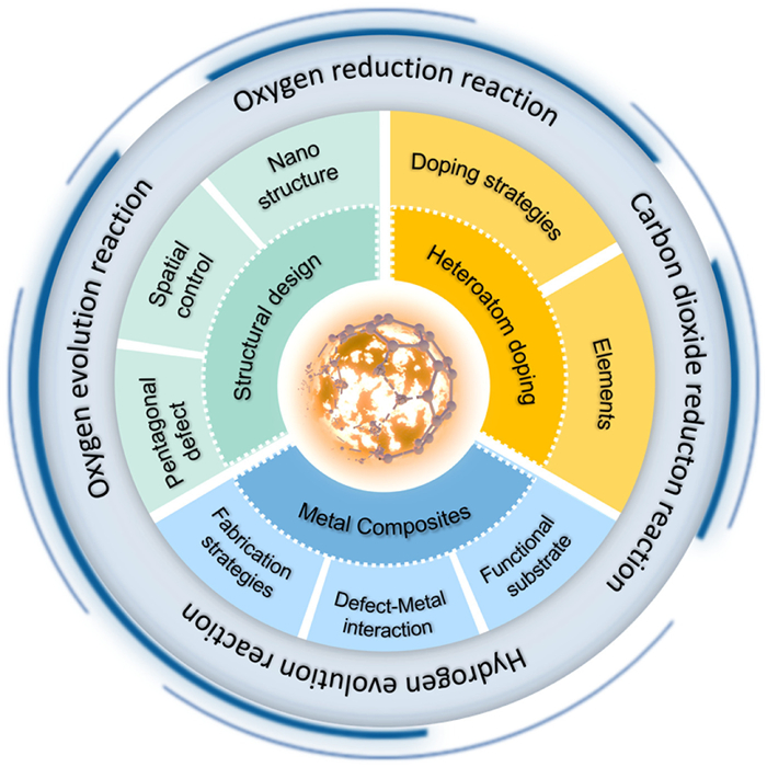
Figure 1.
Pyrolyzed fullerene-based electrocatalytic materials: A framework diagram of multidimensional design strategies and multiple application scenarios.

Electrocatalytic carbon materials derived from fullerene pyrolysis
Yuxiang Wang , Yutong Xu , Weiwei Zeng , Xinxing Zhan , Jinliang Zhuang , Yuan-Zhi Tan


Developing new energy sources and exploring green energy conversion strategies are essential solutions to address urgent global challenges of energy depletion and environmental pollution [1-4]. Among the various approaches to energy transformation and upgrading, electrocatalysis stands out as a crucial field in green chemistry. It enables the conversion of substances into efficient new energy sources and valuable chemicals, and effectively addresses energy depletion, reducing reliance on fossil fuels. In recent years, significant advancements have been made in this field [5-8]. The pursuit of catalysts that exhibit multiple active sites, high selectivity, sustainability, and environmental friendliness remains a key area of research [9,10].
Carbon materials possess several prominent advantages: They are abundant in reserves, diverse in types, and sustainable, enabling large-scale production at low cost, thus attracting significant attention in the field of electrocatalysis [11]. In 2009, Dai et al. [12] first proposed using nitrogen-doped carbon nanotubes (N—CNTs) as metal-free, heteroatom-doped carbon-based catalysts (C-MFCs) to replace platinum in fuel cells. This approach demonstrated excellent ORR performance and paved the way for the development of carbon-based electrocatalysts. Over the years, the family of carbon materials applied in electrocatalysis has expanded significantly to encompass various hybridized carbon materials [13-15]. sp3-hybridized carbons (e.g., diamond and diamond-like carbon) feature a three-dimensional framework with high chemical stability and low surface impurity adsorption, yet suffer from poor electrical conductivity [16]. sp-Hybridized carbons may exhibit unique linear or directional characteristics relevant to electrocatalytic applications, but their synthesis remains a significant challenge [17]. In contrast, sp2-hybridized materials (e.g., graphenic carbon) demonstrate excellent electrical properties and are widely accessible. Current research mainly focuses on sp2-conjugated materials (including graphene, carbon nanotubes), and has been continuously extended to their atomic hybrid derivatives and metal composite products [18-23]. These materials are being constantly advanced toward industrial research and development.
Fullerenes, a unique class of sp2-hybridized carbon allotropes, exhibit remarkable electron affinity and considerable electrocatalytic potential [24-28]. However, their broader application is hindered by inherent limitations such as low electrical conductivity, limited specific surface area, and weak intrinsic catalytic activity due to electronic neutrality. With the growing recognition of the catalytic role of edge and pentagonal defects [29-33], the pyrolytic fragmentation and reconstruction of fullerenes have emerged as an effective top-down strategy to overcome these constraints. This process yields carbon materials with substantially enhanced conductivity, abundant edge sites, defect-rich structures, and integrated high-curvature pentagonal features. Moreover, properties of the resulting pyrolyzed fullerene-derived carbons can be finely tuned through hierarchical structuring, heteroatom doping, and metal incorporation [34-36], which collectively enhance catalytic activity and broaden applicability across various reactions. Owing to these distinct structural advantages, such materials have attracted considerable research attention. Although the electrocatalytic performance of fullerenes and their derivatives has been reviewed [37,38], a systematic overview dedicated specifically to pyrolyzed fullerene-derived carbon electrocatalysts is still lacking.
This review begins by elaborating on the structural evolution, merits, and characterization of pyrolyzed fullerene-derived carbons. It then details design principles: Encompassing hierarchical structuring, heteroatom doping, and metal incorporation, and evaluates their catalytic performance across diverse reactions (Fig. 1). Finally, future perspectives are proposed, outlining the key challenges and opportunities in this emerging field to guide the rational design of next-generation pyrolyzed fullerene-derived carbon electrocatalysts.
The thermal stability and transformation pathways of fullerenes have been a subject of intense study since their discovery. The intrinsic strain in the C60 molecule arises primarily from the angular distortion introduced by its twelve pentagons within the cage structure. The bond angles between carbon atoms (~108°) are generally smaller than the ideal sp2 angle of 120°, while two distinct types of chemical bonds, [5,6] bonds and [6,6] bonds, exhibit differences in bond length. This geometric strain renders the molecule metastable and susceptible to structural evolution under external stimuli.
In 1993, Scuseria and co-workers elucidated that annealing drives Stone–Wales transformations within the carbon cage; this topological rearrangement can precipitate the elimination of C2 fragments and the reconstruction into new closed cages [39]. Concurrently, researchers began to systematically explore the influence of other external stimuli, such as pressure, temperature variations, and the presence of catalysts, on fullerene transformation [40-43]. It is now well-established that under distinct conditions, fullerenes can evolve into a diverse array of carbon architectures (Fig. 2).
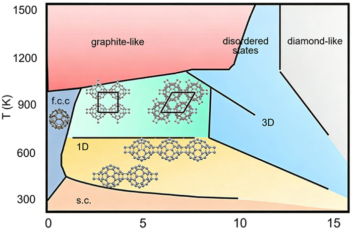
The thermal conversion behavior of fullerenes under inert, ambient-pressure atmospheres exhibits a strong temperature dependence. At relatively low temperatures, fullerene molecules display high thermal stability [44]. Radhakrishnan et al. observed that upon heating above 700–800 ℃, the fullerene cage structure begins to irreversibly collapse, progressively transforming into amorphous, disordered carbon [45]. Numerous subsequent studies have confirmed that under high-temperature ambient-pressure conditions, the pyrolytic products of fullerenes predominantly consist of amorphous or turbostratic carbon [46-48], featuring abundant curved graphene-like sheets, pentagonal/heptagonal ring defects, and edge sites—structural motifs widely recognized as potential active sites in electrocatalysis. In common with other carbon materials, higher pyrolysis temperatures increase the overall graphitization degree, resulting in a lower defect density [49].
Under high pressure conditions, the intermolecular distance of fullerenes decreases. Within a moderate temperature range, C60 molecules typically undergo [2 + 2] cycloaddition to form cyclobutane rings, yielding (C60)2 dimers at approximately 1 GPa, and further polymerize into diverse dimensional structures with increasing pressure: One-dimensional (1D) chains below 2 GPa, two-dimensional (2D) layered phases between 2 and 8 GPa, and three-dimensional (3D) networks above 8 GPa (Fig. 2) [41,50-54]. Disordered graphite-like carbon phases can be formed via high-temperature (HT) treatment of 2D polymers, while disordered diamond-like carbon phases are obtained by HT treatment of 3D polymers at temperatures above 1000 K [41]. Notably, a third pathway involves the catalytic decomposition of fullerenes by transition-metal catalysts at ambient pressure and elevated temperatures. The released carbon species dissolve, diffuse, and precipitate on metal particles, growing into well-defined nanostructures such as carbon nanotubes and graphene sheets [55-57].
Among the resulting materials, diamond phases usually exhibit low electrical conductivity and inefficient electron transport due to their high fraction of sp3-hybridized bonds [58], which is detrimental for electrocatalysis. In contrast, graphite-like carbons and two-dimensional C60-based polymers show particular promise for catalytic applications. The former has been extensively studied owing to its continuous sp2-conjugated network, excellent conductivity, and abundant intrinsic defects. The latter, though requiring more stringent synthesis conditions, offers structural precision and high-density active sites within an ordered, conductive framework. Precise tuning of pyrolysis reaction conditions enables the differential modulation of the sp2/sp3 hybridization ratio, defect density, and exposed pentagonal ring sites, thereby facilitating the directional design of various electrocatalysts tailored for specific application scenarios.
Pyrolyzed fullerene-derived carbons possess structural advantages over conventional precursors (e.g., graphene, carbon nanotubes, and biomass), originating from two intrinsic characteristics of fullerene molecules: Their curved cage architecture and abundant pentagonal rings. This curved geometry facilitates intermolecular cross-linking and reconstruction during pyrolysis, forming a three-dimensional (3D) interconnected network that endows the resulting carbon with high specific surface area, hierarchically interconnected porosity, and robust structural stability. In contrast, graphene sheets are prone to restacking driven by van der Waals interactions, which restricts access to their theoretical surface area [59]. Similarly, while carbon nanotubes offer high surface area, their accessible porosity is largely confined to one-dimensional intertubular spaces or internal channels, leading to substantially constrained ion diffusion kinetics.
Second, the pentagon-rich framework facilitates the generation and retention of abundant topological defects during carbonization. Unlike pre-graphitized graphene or carbon nanotubes (CNTs), which necessitate additional activation to introduce defects or crosslinks [60,61], fullerenes directly yield a defect-rich, interconnected carbon architecture via one-step pyrolysis. In contrast to biomass-derived carbons with random, ill-defined defect distributions, fullerene-derived materials provide a uniform and structurally correlated defect network, predominantly composed of pentagonal rings, inherited from their molecular precursors [62].
Moreover, the high intrinsic reactivity of pentagonal rings, curved carbon surfaces and edge sites renders fullerene-derived carbons highly amenable to heteroatom doping during pyrolysis [63-66]. Whereas heteroatom incorporation in graphene or CNTs typically relies on post-treatments or harsh activation, the strained curved framework of fullerenes lowers the energy barrier for substitutional or edge-site doping. This enables higher doping efficiency and more homogeneous dopant distribution.
Therefore, by integrating high defect density, tailorable sp2/sp3 hybridization, efficient heteroatom doping, and an interconnected conductive network within a molecularly defined precursor system, fullerene-derived carbons quantitatively and structurally outperform many conventional carbon materials. This provides an ideal platform for the rational design of high-performance electrocatalysts.
The electrocatalytic performance of pyrolyzed fullerene-derived carbon materials is strongly dependent on intrinsic parameters such as defect density, type, distribution location, electronic conductivity, and pore structure. Therefore, establishing a systematic characterization methodology is crucial for unveiling their structure–property relationships and guiding rational design.
The graphitization degree of pyrolyzed fullerene-derived carbons is highly dependent on the pyrolysis temperature, which can be readily monitored by the evolution of the (002) diffraction peak in X-ray diffraction (XRD) patterns. A sharp and intense (002) diffraction peak appearing near the characteristic diffraction angle of standard graphite (ca. 26.5°) indicates the formation of a highly graphitized product with a long-range ordered structure at elevated temperatures. Conversely, the broadening of the (002) peak and its shift toward lower angles are characteristic of the formation of an amorphous structure.
The morphological and structural characteristics of pyrolyzed fullerene materials, spanning from microscopic architecture and porosity to atomic-scale defects, fundamentally govern their specific surface area and, mass transfer capability. Scanning electron microscopy (SEM) directly reveals the macroscopic morphology of materials, capturing features such as hollow microspheres, three-dimensionally interconnected networks, and hierarchical porous frameworks. Transmission electron microscopy (TEM), particularly in the high-resolution mode (HRTEM), can resolve key microstructural features such as pore size, atomic edge structures, and curvature [67]. When coupled with energy-dispersive X-ray spectroscopy (EDS) mapping, this technique can also visualize the spatial distribution of heteroatoms within doped materials. At the atomic scale, aberration-corrected scanning transmission electron microscopy (AC-STEM) enables direct imaging of topological defects, including five- and seven-membered carbon rings, providing critical evidence for defect-engineering strategies [68]. Complementarily, high-angle annular dark-field STEM (HAADF-STEM) exploits Z-contrast imaging to selectively identify heavy elements, allowing precise characterization of supported metal nanoparticle morphology and dispersion on carbon substrates [69]. Gas physisorption analysis enables precise determination of the specific surface area and pore size distribution of pyrolyzed fullerene-derived carbons.
Raman spectroscopy sensitively probes the defect structure of pyrolyzed fullerene carbon materials. The ID/IG intensity ratio directly quantifies network disorder. Spectral deconvolution identifies specific defects, with the D3 band (~1500 cm-1) explicitly assigned to intrinsic pentagonal rings. The increase in D3/G quantitatively correlates with a higher density of these topological defects and a lower graphitization degree. Near-edge X-ray absorption fine structure (NEXAFS) reveals the corresponding electronic structure evolution. The broadened and diminished C K-edge π* peak corroborates the Raman data, directly evidencing the disruption of the π-conjugated system and electron localization induced by pentagonal-ring defects [70]. EPR provides complementary evidence, showing a pronounced spin signal indicative of abundant paramagnetic centers. Consistent with the precursor-derived structure and spectroscopic signatures, these centers are unambiguously ascribed to topologically defined defects, primarily pentagonal rings. Furthermore, other effective characterization techniques for analyzing the structural defects of carbon materials also include positron annihilation spectroscopy (PAS) and ultraviolet photoelectron spectroscopy (UPS).
X-ray photoelectron spectroscopy (XPS) is a core technique for elucidating the chemical states of pyrolyzed carbon materials, and particularly applicable to the characterization of doped and modified materials. For N-doped materials, the XPS N 1s spectrum can effectively distinguish between nitrogen species with distinct chemical states (e.g., pyridinic N, pyrrolic N, and graphitic N) and quantify their atomic contents [71]. The relative contents of different nitrogen species directly modulate the electronic structure and stability of catalytic active sites, thus providing vital chemical insights for identifying active sites with high precision and unraveling the underlying catalytic mechanism. Furthermore, XPS can quantitatively determine the sp2/sp3 carbon ratio, a key parameter that is directly correlated with the electronic conductivity of the material.
The electrocatalytic performance of pyrolyzed fullerene-derived carbons is intrinsically governed by a hierarchical structural design spanning atomic defects to micro-/nanoscale architecture. At the atomic level, intrinsic features such as pentagonal rings and curvature modulate the local electronic structure [34,72]. On the mesoscale, spatial confinement during pyrolysis directs carbon-fragment reconstruction, tuning the sp2/sp3 hybridization ratio and the distribution/density of active sites [73]. At the micro-/nanoscale, morphology control, pore engineering, and templating strategies further promote defect exposure, mass/charge transfer, and structural stability [74]. Importantly, high-performance catalysts emerge not from isolated structural advantages, but from the synergistic integration of multiscale designs. Accordingly, this section examines three intertwined levels: The role of intrinsic carbon defects, the effect of spatial confinement on defect evolution, and micro-/nanostructural engineering for enhanced electrocatalysis.
Although nitrogen doping improves catalyst performance, the correlation between doping concentration and catalytic activity remains debated. Consequently, a defect-driven mechanism has been proposed, in which intrinsic defects are considered the primary active sites. Hu et al. [67] demonstrated that pentagonal and zigzag edge defects in pure carbon nanocages lower the ORR free-energy barrier relative to pristine sp2 carbon (Fig. 3a). Yao et al. [75] provided the first experimental evidence that G585 defects facilitate O2 conversion to *OOH during ORR with reduced activation energy, thereby enhancing catalytic performance (Figs. 3b and c). The field widely acknowledges pentagonal rings as critical defect sites, which induce geometric curvature and electronic redistribution in the carbon skeleton, creating numerous active centers.
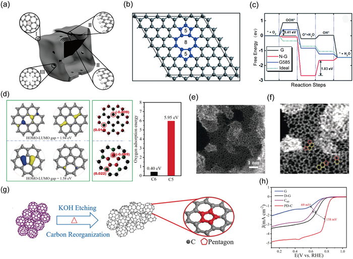
In 2018, Mu et al. [34] theoretically demonstrated that pentagonal rings have narrower band gaps than hexagonal rings, facilitating electron transfer (Fig. 3d). Subsequently, they successfully prepared PD-C material rich in pentagonal defects via high-temperature KOH pyrolysis of C60 (Fig. 3g). AC-STEM directly confirmed the preservation of pentagonal defects (Figs. 3e and f). Electrochemical tests revealed that PD-C displayed enhanced four-electron ORR activity with a positive-shifted onset potential relative to pristine C60 (Fig. 3h), strongly verifying the critical catalytic role of pentagonal defects.
The pentagonal ring density in pyrolyzed fullerene-derived carbons plays a critical role in ORR performance. Zeng et al. [76] revealed via DFT that pentagon-rich C60 fragments remarkably reduce the ORR overpotential by strengthening the adsorption of *OH and *OOH intermediates (Figs. 4b and c). Nitrogen dopant extraction from nitrogen-doped carbon generates efficient intrinsic defects, a strategy likewise applicable to boosting pentagonal-ring density in fullerene-derived carbon [77]. Lu et al. [78] found that, compared with structurally ordered fullerene fibers (FF), pre-pyrolyzed carbon (FC) exhibits higher structural disorder and can expose more in-plane doping sites centered on pentagonal rings (Fig. 4a). Further removal of dopants induces the formation of pentagon–heptagon–pentagon topological defect structures, which effectively increases the pentagonal ring density and thus enhances the electrocatalytic performance (Fig. 4d). However, it should be noted that excessive defects can lead to structural instability and poor conductivity, which therefore calls for rational design. With increasing defect density, the number of catalytic active sites in carbon materials increases, yet excessive defects destroy the integrity of the sp2-carbon framework and reduce electrical conductivity. Meanwhile, highly defective sites are susceptible to electrochemical oxidation and structural collapse, resulting in inferior stability. Thus, there is a clear trade-off among defect density, conductivity, and stability.
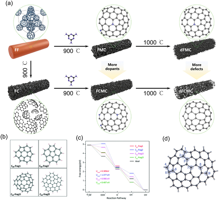
In addition to the absolute density of pentagonal rings, the macroscopic symmetry and the microscopic local environment of the carbon framework are also critical structural factors for tuning catalytic performance. Zeng et al. [76] found that fullerene-derived carbon materials with lower structural symmetry exhibit enhanced oxygen reduction reaction (ORR) activity (Figs. 4b and c). This improvement is attributed to the elevated energy level of the highest occupied molecular orbital (HOMO) in low-symmetry architectures. Therefore, rationally increasing the pentagonal ring density and reducing the carbon structural symmetry are of great significance for boosting the catalytic activity of fullerene-derived carbons.
Curvature serves as another critical design parameter for modulating the electronic structure of catalysts, which is achieved through the re-hybridization of carbon orbitals and the redistribution of local charge. For instance, Ozika et al. [79] demonstrated that warped graphitic layers (WGLs) derived from fullerene extraction residues via pyrolysis at 1250 ℃ achieved an optimal oxygen reduction reaction (ORR) half-wave potential (E1/2) of 0.79 V vs. RHE. In pyrolyzed fullerene-derived carbons, Lu et al. [72] fabricated highly curved carbon nano-onions via the co-pyrolysis of melamine and C60, with the simultaneous incorporation of pentagonal ring defects and nitrogen doping. The resulting material exhibited outstanding ORR performance. More pentagons can endow the pyrolyzed carbon skeleton with a higher curvature, resulting in enhanced orbital hybridization and charge redistribution, which is more beneficial for the improvement of catalytic activity.
Based on the structural evolution patterns during fullerene pyrolysis, pressure drives the formation of sp3-hybridized carbon or diamond phases, whereas the absence of pressure favors the formation of thermodynamically stable sp2-hybridized carbon. This process is primarily governed by the spatial confinement effect induced by pressure. Drawing inspiration from this, Lu et al. [73] employed a silica-mediated spatial-confinement strategy to systematically probe how spatial proximity alters the recombination pathways of fullerene fragments. Under open-space conditions (SiO2 etched before heating), free C60 fragments connect preferentially via edges, yielding larger sp2-hybridized graphene nanosheets with abundant pentagonal defects (denoted E-H-5). In contrast, under confined-space conditions (heating before SiO2 etching), adjacent fragments undergo face-on connection (denoted H-E-5), promoting sp3-hybridized carbon formation, which reduces electron-transport efficiency and limits the exposure of active sites (Fig. 5a). Consequently, the E-H-5 material, characterized by its large, sp2-rich graphitic nanosheets, exhibits significantly higher catalytic activity than the sp3-rich H-E-5 material, owing to its superior electrical conductivity and greater exposure of defect sites.
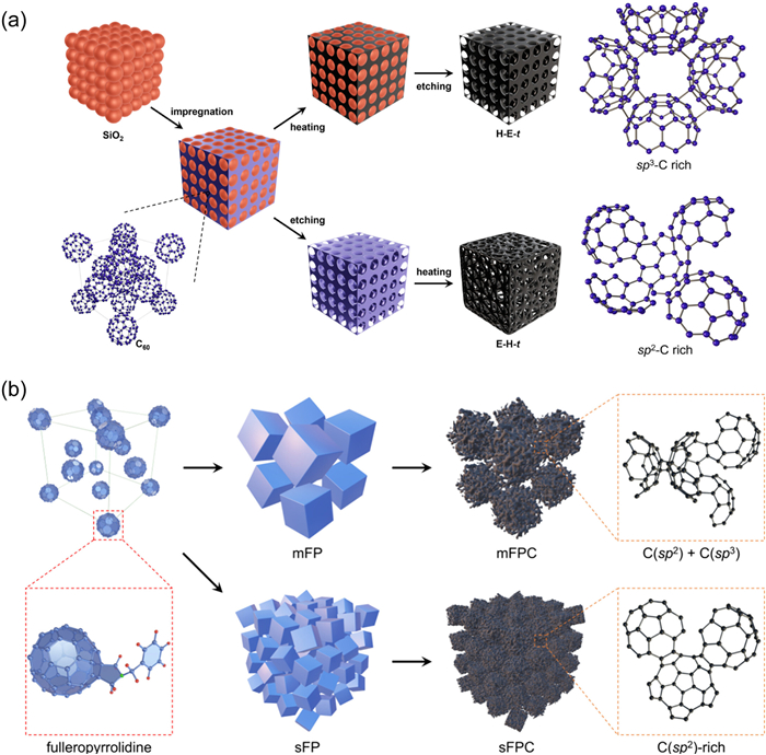
Similarly, by engineering a fullerene derivative (C60-pyrrolidine), Lu et al. [80] have achieved precise control of chemical spatial proximity and hybridization ratio and increased exposure of pentagonal defects during pyrolysis (Fig. 5b). This strategy enables the ORR performance to outperform that of commercial Pt/C.
While atomic-level regulation is critical, the microstructure and nanostructure of pyrolyzed fullerenes are equally indispensable for enhancing electrocatalytic performance. Suppressing the disorder and aggregation of precursors during pyrolysis via the liquid–liquid interface precipitation (LLIP) or templating method can promote the exposure of more pentagonal defects, facilitate efficient mass and charge transport, and thus endow the material with outstanding electrocatalytic performance.
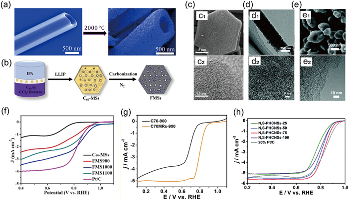
The LLIP pre-assembly strategy organizes fullerenes into well-defined precursors under interfacial confinement, which preserves their regular morphology during subsequent pyrolysis and effectively addresses the inherent disorder and aggregation of fullerenes in direct pyrolysis. Ariga et al. [81] demonstrated that 1D fullerene tubes maintained structural integrity even after high-temperature pyrolysis, converting into porous carbon materials at 2000 ℃ while retaining the original 1D morphology (Fig. 6a). This feature not only facilitates mass transport in pyrolyzed fullerenes but also exposes more pentagonal-dominant defect sites, thereby boosting electrocatalytic performance. Lu et al. [74] synthesized C60 microsheets via interfacial synthesis (Fig. 6b) and subsequent simple heat treatment to produce a series of flake-like carbon materials (FMSs). Scanning electron microscopy (SEM) characterization revealed well-defined flake-like morphologies (Fig. 6c). Notably, the FMS1000 sample (where 1000 denotes the pyrolysis temperature) exhibits superior electrocatalytic activity, with an onset potential of 0.85 V vs. RHE and remarkable stability (Fig. 6f), which is primarily attributed to its flake-like morphology that endows it with a hierarchical pore structure and abundant structural defects. Using a similar methodology, the authors also fabricated a highly porous, defect-rich carbon material (C70MRs-900) while maintaining the original rod-like morphology (Fig. 6d) [82]. Notably, the rod-shaped C70MRs-900 exhibited significantly superior electrocatalytic ORR activity compared to its disordered counterpart (C70–900) (Fig. 6g). Furthermore, porous hollow carbon nanospheres were synthesized [83] via annealing with the team-prepared fullerene spheres as precursors. SEM and transmission electron microscopy (TEM) characterizations confirmed that the as-synthesized nanospheres possess a spherical hollow architecture (Fig. 6e), and their half-wave potential closely approximates that of commercial Pt/C (Fig. 6h).
The nanotemplate method enables more efficient and controllable fabrication of customized ordered porous carbon materials [84-86], thereby further optimizing mass transport, active site accessibility, and electron conduction efficiency during electrocatalysis. Ajayan Vinu et al. [87] utilized SBA-15 (mesoporous silica) as a template to encapsulate 1-chloronaphthalene-grafted C60 within its matrix, resulting in the ordered mesoporous carbon material named MFC60-T (where T denotes the synthesis temperature of SBA-15) after annealing. Due to the ordered mesoporous structure of the material, MFC60–130 exhibits outstanding ORR activity in an oxygen-saturated electrolyte. Moreover, this method was also successfully applied to synthesize C70-based carbon electrocatalyst for ORR [88].
Building on the foundation of suppressing carbon precursor agglomeration and guiding the formation of hierarchically porous structures using templates, further increasing the density of pentagonal defects can significantly enhance ORR activity. Nakamura et al. [89] synthesized a cage-like carbon material using cubic NaCl templates. Through subsequent pyrolysis, they deliberately removed pyridinic nitrogen, thereby exposing more pentagonal defects for acidic ORR. They elucidated that these pentagonal rings, owing to their localized high spin density, serve as key active sites for efficient oxygen adsorption, ultimately leading to a significant improvement in the ORR performance of the material in acidic media.
The electrochemical activity of carbon materials primarily originates from their intrinsic defects, such as the inherent pentagonal-ring topological defects in pyrolyzed fullerenes. Nevertheless, in the absence of heteroatom doping, pure carbon materials exhibit limited tunability in Fermi level and electron density, hindering precise adjustment of the adsorption energies (e.g., for *OOH) toward the ideal "moderate" window. Introducing heteroatoms synergistically modulates the local charge distribution around these pentagonal defects, thereby optimizing the adsorption strength of intermediate species (e.g., for *OOH). This tunability not only enhances performance in the four-electron ORR pathway or directs selectivity toward the two-electron route but also holds promising potential for other catalytic applications. Heteroatoms can be readily incorporated into the defect sites of carbon materials, particularly at highly reactive locations such as edges and pentagonal rings [63-66]. In pyrolyzed fullerene-derived carbons, the presence of these intrinsic defects significantly facilitates the substitution of framework carbon atoms by heteroatoms, leading to the formation of abundant dopant-defect composite active sites. This section reviews recent advances in this field, with a focus on doping strategies, the synergistic mechanisms between dopants and pentagonal-ring defects, and their regulatory effects on electrocatalytic performance.
Heteroatom doping is mainly achieved through two strategies, one being the additive doping method. This technique enables the in-situ formation of reactive heteroatom species via thermal decomposition, followed by their incorporation into the carbon framework. For instance, Zhu, Ruoff, and co-workers successfully prepared nitrogen-doped porous carbon by introducing NH3 into a mixture of C60 and KOH under high-temperature conditions [48]. This approach allows relatively uniform heteroatom doping through a straightforward thermal treatment process. It is noteworthy that the specific type of dopant significantly influences the resultant doping efficacy.
The second strategy involves the use of fullerene derivative precursors for doping. In this approach, heteroatom-containing substituents are grafted onto the surface of fullerenes, followed by pyrolysis to incorporate the dopants into the carbon matrix. For example, C60 with covalently attached ethylenediamine was used to produce nitrogen-doped fullerene hollow spheres (N@FHS). These were then mixed with pyrophosphoric acid and pyrolyzed, yielding N, P co-doped carbon hollow spheres [90]. Compared to the additive doping method, this precursor-based approach, while entailing greater synthetic complexity, offers superior control over the dopant's position and chemical environment within the carbon lattice, leading to a more homogeneous distribution.
Nitrogen (N) is one of the most representative dopants for carbon materials. Its function originates from the electronegativity difference between N and C, which effectively modulates the charge density of adjacent carbon atoms and thus activates these carbon sites [12]. Nitrogen doping mainly generates local configurations such as pyridinic N, pyrrolic N, and graphitic N (Fig. 7a) [91]. Edge and defect sites generally favor nitrogen doping. The abundant intrinsic defects in pyrolyzed fullerene-derived carbons provide an ideal platform for nitrogen doping, which can synergistically regulate the local electronic structure together with the doped nitrogen.
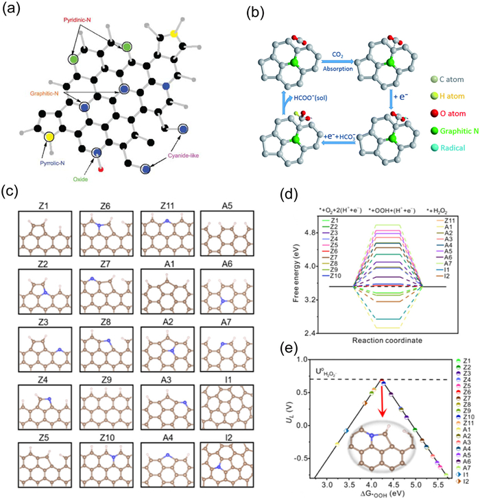
In the electrocatalytic reduction of CO2, nitrogen-doped pyrolyzed fullerene-derived carbons exhibit notable activity. Liu et al. [35] reported that such materials can selectively reduce CO2 to formate. Among them, the N—C61–800 sample pyrolyzed at 800 ℃ showed the best performance, achieving a Faradaic efficiency for formate of 91.2% at an overpotential of 0.7 V. The formate yield correlated positively with the content of graphitic N, indicating that graphitic N serves as the key active site for CO2 adsorption and activation. The proposed reaction pathway is as follows: CO2 adsorption on the graphitic-N site → one-electron reduction to a CO2-• radical intermediate → proton-coupled electron transfer forming adsorbed HCOO- → desorption (Fig. 7b). Although this work clarifies the role of graphitic N, it does not fully address the contribution of intrinsic pentagonal rings.
In fact, in pyrolyzed fullerene-derived carbons, pentagonal rings and nitrogen defects act synergistically to significantly enhance the regulation of the local electronic structure of the carbon framework, thereby tuning the adsorption capability of reaction intermediates. Lu and colleagues [70] prepared a pentagon-rich, defect-abundant N-doped carbon catalyst via direct pyrolysis of fullerene with NH3. The synergy among surface curvature, pentagonal defects, and graphitic-N doping remarkably modulates the geometric and electronic structure of the carbon material. DFT calculations revealed that at the pentagon–graphitic–N interface, the free energy reaches 3.50 eV, close to the ideal value of 3.52 eV, confirming the cooperative enhancement between pentagonal defects and graphitic-N doping (Figs. 7c and d). This interfacial structure optimizes the adsorption of the *OOH intermediate, promotes electron transfer to *OOH, and thereby improves both the overall ORR activity and the selectivity toward H2O2 (Fig. 7e).
To develop efficient multifunctional electrocatalysts for HER, ORR, and OER, carbon materials must integrate diverse active sites capable of adsorbing key intermediates such as *OOH, *OH, and *O. Toward this goal, Lu et al. [92] employed NaCl as a spatial confiner to fabricate an O/N-enriched graphitic sp2-carbon matrix. Subsequent pyrolysis generated pores and removed pyridinic N and O, resulting in a defect-rich carbon architecture containing vacancies, edges, and pentagonal rings. The resulting material demonstrated outstanding trifunctional electrocatalytic performance, primarily arising from the synergy between graphitic N and the defective carbon framework.
Sulfur (S) possesses an electronegativity slightly higher than carbon (C) yet substantially lower than nitrogen (N). The primary doping mechanism involves the disruption of the carbon lattice symmetry, leading to charge redistribution and the generation of high spin densities on adjacent carbon atoms via spin polarization. This modifies the local charge environment [93]. The limited charge transfer between S and the carbon matrix, however, is insufficient to surmount the energy barrier for O–O bond scission. This inherently steers the selectivity toward H2O2 production via the 2e- ORR pathway, rather than the complete 4e- reduction to H2O [94]. Furthermore, the large covalent radius of sulfur thermodynamically favors its incorporation into coordinatively unsaturated sites, such as edges, vacancies, and other defects, within the carbon matrix. Pyrolyzed fullerene-derived carbons, inherently abundant in such topological defects, offer an ideal host for S doping. More importantly, the incorporated sulfur sites synergize with the intrinsic pentagonal-ring defects to precisely tailor the interfacial charge and spin density, ultimately optimizing the electrocatalytic performance. Lu, Lv and Du et al. [95] synthesized sulfur-doped defective nanocarbon (S-DNC) through direct pyrolysis of sublimed sulfur and fullerene. S-DNC exhibits a porous, amorphous structure (Figs. 8a and b) with irregular folds and curved edges (Fig. 8c), indicative of abundant topological defects. EDS mappings confirm the homogeneous distribution of C and S (Figs. 8d-g). The electrode delivered a high H2O2 yield of 690 mg L−1 h−1 with near-quantitative Faradaic efficiency (~100%). DFT calculations of Gibbs free energies for various models (Fig. 8h) identified the A2 configuration with the most favorable energy profile (Fig. 8i), situated at the top of the activity volcano (Fig. 8j). These results demonstrate that topological pentagonal defects and S dopants act synergistically to optimize *OOH adsorption, promote charge redistribution (Fig. 8k), and thus markedly enhance 2e− ORR catalysis.
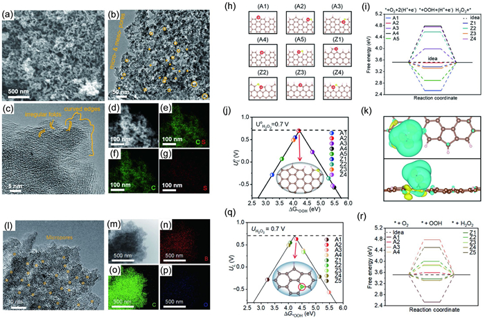
Compared with carbon, boron exhibits a lower electronegativity, causing adsorption to predominantly occur on B sites. The relatively weak oxygen adsorption affinity of boron renders it more suitable for promoting H2O2 formation [96-98]. Lu, Lv, Du et al. [99] synthesized boron-doped nanocarbon (B-DC) electrocatalysts via high-temperature pyrolysis using boron-doped defective fullerene skeletons as precursors and boron oxide as the boron source. The resulting B-DC possesses a well-developed mesoporous architecture (Fig. 8l) and uniform boron doping, as confirmed by EDS (Figs. 8m-p). It achieves an H2O2 production rate of 247 mg L−1 h−1 with a Faradaic efficiency approaching 100%. DFT calculations reveal that a BC3 configuration (Model A2), which shares a carbon atom with an adjacent pentagonal defect, lies near the top of the volcano plot and serves as an ideal active site for the 2e- ORR (Figs. 8q and r).
Compared with single-element doping, multi-element co-doping can form an enhanced synergistic effect with the pentagonal defects of fullerene-pyrolyzed carbon. For instance, Huang and co-workers designed N/O co-doped pyrolytic carbon from fullerenes to promote CO2 reduction [100]. The co-doping of N and O modulates the electronic structure, synergistically facilitating the formation of *COOH intermediates and enhancing the activity and selectivity for CO production. Ji et al. [90] reported P/N co-doped pyrolytic spheres derived from fullerenes, which showed significantly better ORR performance than single N-doped counterparts and commercial Pt/C (20 wt%). The enhanced ORR activity primarily arises from the strong electronegativity of P/N co-doped carbon sites and their synergistic interaction with the defective pentagonal rings in the fullerene structure.
In metal–carbon composite catalytic materials, the defective or heteroatom-doped carbon matrix not only acts as additional active sites but also facilitates electron transfer via constructing interfaces with metal components, thereby yielding a remarkable synergistic catalytic effect [101-103]. Pyrolytic carbon materials derived from fullerene precursors are intrinsically abundant in pentagonal topological defects that can form strong interactions with metal active centers [104,105]. Meanwhile, they possess tailorable derivatization properties, which render them an ideal scaffold for fabricating uniform metal–carbon composite structures. Furthermore, fullerenes themselves exhibit a unique electron modulation mechanism that can further optimize the electronic structure and catalytic performance of the composite system [26]. In this section, we systematically summarize the preparation strategies of fullerene-based metal–carbon composite catalytic materials, elucidate the synergistic interaction mechanism between pentagonal rings and metal active centers, and discuss the application value of fullerenes as a multifunctional platform in the design and regulation of such catalytic materials.
Two principal strategies are established for constructing metal-pyrolyzed fullerene composites. The first leverages the π-conjugated framework and intrinsic defects (e.g., vacancies, edges, pentagonal rings) of pre-formed pyrolyzed fullerene-derived carbons. Herein, relatively weak π–metal interactions facilitate the initial dispersion of metal species [104], while stronger chemical bonds at defect sites enable their precise anchoring. This synergy effectively mitigates metal aggregation and sintering, ensuring a stable interface for catalysis.
In contrast, the second strategy employs a "bottom-up" approach by pre-anchoring metal sites onto fullerene molecules via coordination bonds prior to pyrolysis [106]. This method ensures atomic-level metal dispersion within the resulting sp2-carbon matrix and offers superior control over the local structure of active sites, as the metal–carbon architecture is preset at the molecular level.
The synergism between carbon defects and metal single atoms is widely recognized as a core strategy for boosting the catalytic performance of carbon-based composites. Topological defects, including edges, vacancies, and pentagon/heptagon defects, can serve as anchoring sites to efficiently trap and stabilize metal single atoms or nanoparticles [107-110]. Moreover, in nitrogen-doped carbon matrices (e.g., the typical M–N4 configuration), defect structures such as local curvature, edge and five-membered rings allow for precise modulation of the local coordination environment and electronic density of states of metal centers [111-114]. These observations unveil a common physical origin: Carbon defects inherently act as dynamic regulators of the local electronic structure. Via orbital hybridization and coupling with the metal d-band center, they trigger directional electron transfer between the metal sites and defective carbon frameworks. Such well-controlled charge redistribution significantly optimizes the adsorption free energies of key reaction intermediates (e.g., *OOH, *COOH, *H) on metal sites, thus enhancing ORR activity and being applicable to other catalytic reactions. Pyrolyzed fullerenes inherently form dense networks of edge defects composed of pentagonal rings and dangling bonds, offering an ideal platform for establishing strong electronic interactions with various metals ranging from single atoms to clusters. Lu et al. [104] developed a composite catalyst (FePc/FC) by anchoring iron phthalocyanine (FePc) molecules onto defective carbon (FC) derived from the pyrolysis of C60 (Fig. 9a). Uniform dispersion of FePc was achieved through interactions with intrinsic defect sites in FC, such as pentagonal rings and edge sites, which effectively suppressed molecular aggregation. X-ray photoelectron spectroscopy (XPS) analysis (Fig. 9b) showed a distinct shift in the Fe 2p peaks for FePc/FC compared to pristine FePc, confirming strong electronic coupling between FePc and the defective carbon matrix. Compared with other carbon supports, including reduced graphene oxide (rGO) and carbon nanotubes (CNTs), the FePc/FC (Fig. 9c) composite demonstrated significantly enhanced activity toward the oxygen reduction reaction (ORR).
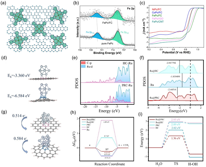
To further elucidate the interaction between isolated pentagonal defects and anchored metal species. Mu et al. [105] systematically elucidated how pentagonal-ring defective carbon (PRC) derived from fullerene modulates the electronic structure of supported Ru clusters. The adsorption energy of Ru clusters (Fig. 9d) on PRC (Eads = −6.584 eV) was substantially more negative than that on conventional carbon supports (HC, Eads = −3.360 eV), indicating that pentagonal-ring defects can effectively anchor and stabilize Ru clusters while mitigating agglomeration. Projected density of states (PDOS) analysis (Figs. 9e and f) further revealed pronounced p-d orbital hybridization between PRC and Ru clusters, promoting electron transfer from Ru to the pentagonal-ring defect sites. The strong metal-support interaction was further confirmed by a near-zero Gibbs free energy change for hydrogen adsorption and a low kinetic barrier for water dissociation (Figs. 9g-i). Consequently, the synthesized Ru/PRC catalyst exhibited high HER activity and remarkable stability across the entire pH range, encompassing acidic, alkaline, and neutral conditions.
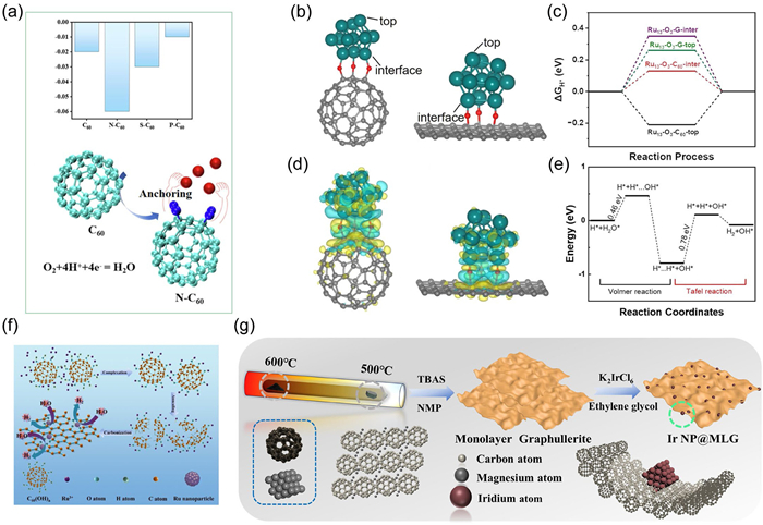
Heteroatom doping is a well-established strategy for modulating the performance of metal-based catalysts [115-117]. Leveraging the electronegativity difference between dopants and host atoms enables precise tuning of the electronic states of metal active sites. Fullerenes, with their unique and tunable molecular framework, allow for the controlled introduction of heteroatoms such as O and N into the carbon cage via hydroxylation, amination, or plasma treatment [118-120]. These incorporated heteroatoms serve as stable anchoring sites for metals, enhancing metal loading and providing a favorable microenvironment. For instance, Xie et al. [121] systematically investigated the effects of N, P, and S doping on Pt-loaded fullerene systems, revealing that nitrogen doping optimizes interfacial charge distribution and strengthens the anchoring of Pt species (Fig. 10a). Moreover, heteroatoms can synergistically modulate the electronic structure of metal centers alongside intrinsic defects through mechanisms such as p-d orbital hybridization and charge transfer. Huang et al. [122] successfully fabricated a Ru-O/C-600 electrocatalyst by pyrolyzing a composite of C60(OH)n and Ru nanoparticles (Fig. 10f). The surface oxygen-containing functional groups induced strong electronic interactions, promoting the formation of uniformly dispersed ultrafine Ru nanoparticles (2.0–3.5 nm in size). The resulting catalyst exhibited significantly enhanced hydrogen evolution activity, requiring overpotentials of only 242 and 383 mV to achieve current densities of 500 and 1000 mA/cm2, respectively—markedly outperforming commercial 20% Pt/C. In a related approach, Ji et al. [123] introduced oxygen-containing functional groups onto fullerene surfaces via oxygen plasma treatment. During subsequent annealing under an NH4Cl atmosphere, this surface modification strengthened the coordination of iron ions, ultimately yielding an Fe, N, O triply doped fullerene-derived carbon material. Density functional theory calculations revealed that the resulting FeN4O active sites reduced the free energy barrier of the rate-determining step to 0.79 eV, thereby significantly enhancing ORR performance. Heteroatom doping within the pentagonal rings of fullerenes induces pronounced charge density redistribution, synergistically facilitating charge transfer.
Further optimization of the microstructure, combined with heteroatom doping, metal modification, and defect engineering, can further enhance the catalytic performance. For example, Ji, Duan et al. [106] combined heteroatom doping with morphological control by using diamine-C60 as a precursor to construct spherical assemblies. Leveraging the confinement effect of the fullerene superstructure and strong Fe–N coordination, they achieved a homogeneous distribution of Fe–N species within porous carbon spheres after pyrolysis, endowing the material with excellent ORR activity. Additionally, Li et al. [124] fabricated a series of nitrogen/cobalt co-doped carbon nanorods with diverse microstructures through self-assembly and subsequent annealing. Among them, the CoTPP/C60–800 sample exhibited superior ORR performance, attributed to its abundant defects, stable Co–Nx sites, and the presence of cobalt nanoparticles.
Under controlled pyrolysis, fullerenes can be transformed into ordered crystalline polymer networks. Through their lattice confinement effect, these frameworks effectively immobilize metal ions and nanoparticles. They therefore function as both a robust structural scaffold and efficient electron-transport channels. Feng, Huang and co-workers [125] utilized the lattice confinement of a three-dimensional crystalline fullerene network (CFN) to in situ anchor dual active sites, ruthenium nanoparticles (NPs) and single atoms (SAs), via a solvothermal-pyrolysis approach, producing the RuNP-RuSA@CFN-800 catalyst. Under alkaline conditions, the electronic synergy between Ru NPs and SAs modulates the surface charge distribution, thereby enhancing the overall hydrogen evolution reaction (HER) kinetics. Furthermore, by tuning pyrolysis parameters such as temperature, pressure, and catalysts, fullerenes can also be converted into two-dimensional (2D) conductive networks [126-128]. Such 2D architectures provide an ideal platform for metal deposition and stabilize the metallic active sites, while their high conductivity facilitates rapid electron transfer. This concept was exemplified by Du et al. [129] who anchored ultrafine iridium nanoparticles on a 2D network (Ir NP@MLG) using a polyol reduction method and evaluated its performance for the acidic HER (Fig. 10g). The resulting composite exhibited exceptional electrocatalytic activity, requiring an overpotential of only 18 mV to achieve 10 mA/cm2, alongside excellent stability.
The unique electronic properties of fullerenes enable direct modulation of the electronic structure of metal active centers, serving as electron donors or acceptors to precisely tune catalytic behaviors, a role validated across multiple systems [130,131]. For example, Zhang et al. [132] demonstrated that fullerenes with charge-buffering capability can promote reversible migration between Ru and RuO2 in Ru-based active species during HER and OER, thereby effectively maintaining the balance of active states throughout the catalytic cycle. The purpose of pyrolysis is sometimes primarily to activate the metal active sites rather than to disrupt the carbon cage structure. Leveraging the electron-accepting nature of C60, Li et al. [133] employed fullerol C60(OH)24 as a functionalized support: RuCl3 was first introduced as a precursor, followed by successful anchoring of highly dispersed Ru nanoparticles via a 300 ℃ thermal treatment. In this system, the oxygen atoms in the hydroxyl groups owing to their strong electronegativity act as stable coordination sites, while the electron-withdrawing nature of C60 induces charge redistribution and enhances the interaction between Ru nanoparticles and the C60 substrate. The lower ΔG(H*) value at the interfacial site and the corresponding reaction energy profile obtained from DFT calculations correlate directly with the enhanced HER activity of the Ru-O-C60 system (Figs. 10b-e). Consequently, the adsorption/desorption behaviors of key reaction intermediates on the fullerene-supported Ru nanoparticles significantly outperform those on graphene-supported counterparts. Another study by Ji et al. [134] revealed that the closed-cage FePc (iron phthalocyanine) composite exhibited superior oxygen reduction reaction (ORR) activity compared with the open-cage carbon composite, because the closed C60 shells effectively regulate the electronic density of states of the Fe–N4 catalytic sites.
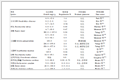
Drawing on the foregoing strategies, this chapter highlights recent key thermally pyrolyzed fullerene-based electrocatalysts for ORR, HER, OER, and CO2RR, along with their core catalytic performances, and summarizes the catalytic properties of several representative electrocatalysts (Table 1).
 DownLoad:
CSV
| Electrocatalyst | Condition | Application | Activity and performance | Refs. |
| PD-C | Alkaline | ORR | E1/2 = 0.78 V | [34] |
| MFC60–130 | Alkaline | ORR | E0 = 0.82 V, E1/2 = 0.76 V | [87] |
| FNCNs-900 | Acidic | ORR | E1/2 = 0.68 V, JL= 4.5 mA/cm2 | [82] |
| Caged-NC-1000 | Acidic | ORR | E0 = 0.76 V, E1/2 = 0.76 V | [89] |
| FMS1000 | Alkaline | ORR | E0 = 0.95 V, E1/2 = 0.85 V | [74] |
| N-PHCNSs-800 | Alkaline | ORR | E0 = 0.917 V, E1/2 = 0.779 V | [90] |
| E—H-5 | Alkaline | ORR | E1/2 = 0.82 V | [73] |
| sFPC | Alkaline | ORR | E1/2 = 0.845 V | [83] |
| PD-NC | Acidic | ORR | E0 = 0.6 V, H2O2 production rate of 2923 mg L−1 h−1 | [70] |
| S-DNC | Alkaline | ORR | E0 = 0.78 V, H2O2 production rate of 690 mg L−1 h−1 | [95] |
| B-DC | Alkaline | ORR | E0 = 0.78 V, H2O2 production rate of 247 mg L−1 h−1 | [99] |
| C60-FePc-500 | Alkaline | ORR | E0 = 1.04 V, E1/2 = 0.91V | [134] |
| FePc/FC | Alkaline | ORR | E1/2 = 0.917V | [104] |
| MN7–10/3 CNT | Alkaline | ORR | E0 = 1.02 V, E1/2 = 0.82V | [140] |
| FeN/C60O-900 | Alkaline | ORR | E0 = 0.98 V, E1/2 = 0.85 V, JL= 5.23 | [123] |
| FeN@FCS-900 | Alkaline | ORR | E0 = 0.93 V, E1/2 = 0.83 V, JL= 4.23 | [106] |
| Cu(15%)-MFC60 | Alkaline | ORR | E1/2 = 0.76 V | [138] |
| Ru-O/C-600 | Alkaline | HER | η10 = 32 mV | [122] |
| Ru-OC60–300 | Wide-range pH | HER | η10 = 4.6 mV (1 mol/L KOH); η10 = 35.5 mV (1 mol/L PBS); η10 = 53 mV (0.5 mol/L H2SO4) | [133] |
| Runp-Rusa@CNF-800 | Alkaline | HER | η10 = 33 mV | [125] |
| Ru@PRC | Wide-range pH | HER | η10 = 58 mV (1 mol/L KOH); η10 = 28 mV (0.5 mol/L H2SO4) | [105] |
| IrNP@MLG | Acidic | HER | η10 = 18 mV | [129] |
| 3-CoFeW | Alkaline | OER | η10 = 205 mV | [36] |
| Ru-FeRu@C/NC | Alkaline | ORR/HER/OER | ORR: E0 = 1.01 V, E1/2 = 0.9 V HER: η10 = 23 mV, OER: η10 = 345 mV | [148] |
| N-C61–800 | Alkaline | CO2RR | E0 = −0.42 V | [35] |
| E0: onset potential; E1/2: half-wave potential; JL: limiting current density; η10: overpotential at a current density of 10 mA/cm2. | ||||
The oxygen reduction reaction (ORR) proceeds through a four-step mechanism involving adsorption, electron transfer, protonation, and desorption [135]. It primarily follows two pathways: The four-electron reduction pathway, which produces water, and the two-electron pathway, yielding high-value hydrogen peroxide [136,137]. Based on the aforementioned strategies, typical catalysts will not be reiterated.
Within the four-electron oxygen reduction reaction (ORR) system, leveraging the high curvature of carbon nano-onions, Lu et al. [72] utilized structural defects in pyrolyzed fullerenes to design and synthesize nitrogen-doped CNO-T catalysts for 4e- ORR (where T represents the calcination temperature). The CNO-900 catalyst demonstrates outstanding electrocatalytic ORR performance, exhibiting a half-wave potential of 0.853 V vs. RHE and superior zinc-air battery cathode performance compared to the commercial Pt/C catalyst (0.838 V vs. RHE). The high catalytic activity originates from the synergistic combination of a high-curvature onion-like architecture, a large specific surface area, abundant edge-active sites, and the exposure of numerous nitrogen-containing pentagonal defect sites. Through nanostructural engineering, Ajayan Vinu et al. [138] successfully developed a mesoporous fullerene (MFC60)-based nanohybrid material loaded with Cu/Cu2O. Among these, the Cu (15%)-MFC60 material exhibits excellent electrocatalytic oxygen reduction reaction (ORR) performance, with an onset potential of 0.860 V versus the reversible hydrogen electrode (RHE) and a diffusion-limiting current density of −5.183 mA/cm2. The enhanced ORR performance is attributed to the synergy between mixed Cu species and the fullerene framework, enabling both efficient mass transport and plentiful active sites. Li et al. [139] incorporated ferrocene into a fullerene system and pyrolyzed the mixture under an NH3 atmosphere, successfully fabricating porous Fe3O4/N-doped carbon composites. Benefiting from the synergistic effect of its porous structure and Fe3O4/N sites, the material shows excellent ORR activity (Eonset = 0.93 V, E1/2 = 0.81 V), coupled with high durability and methanol tolerance. The team further used ferrocene-functionalized C60 pyrrolidine derivatives as precursors for the in situ growth of fullerene-based carbon nanotube (CNT) composites under NH3 [140]. Benefiting from the synergistic effect of high conductivity, large surface area provided by the CNT framework, and abundant metal–N active sites, the MN7–10/3 CNT composite exhibits efficient oxygen reduction performance, with a half-wave potential of 0.82 V and an onset potential of 1.02 V (vs. RHE).
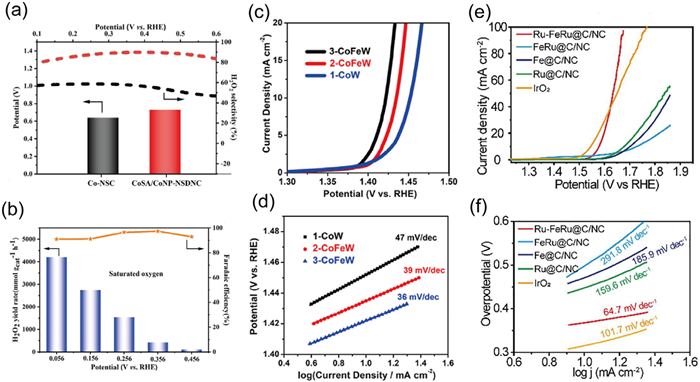
In two-electron catalysis, Benzigar et al. [141] developed ultra-small iron oxide nanoparticles supported on mesoporous fullerene C60 (Fe-MFC60-T, where T indicates the hydrothermal temperature) using a hard template method. The Fe-MFC60–150 variant demonstrated excellent ORR activity, with an onset potential (Eonset) of 0.85 V and a half-wave potential (E1/2) of 0.78 V, alongside a low Tafel slope of 66 mV/dec and remarkable methanol crossover tolerance. This enhanced electrocatalytic performance is attributed to the synergistic effect between the Fe2O3 nanoparticles and the pore structure of mesoporous fullerene C60. Guan et al. [142] synthesized polyhedral carbon micro-nano shells (PCMNS) co-doped with nitrogen and oxygen, resulting in a defect-rich structure. The PCMNS exhibited exceptional H2O2 production efficiency, achieving a yield of 1102.5 mmol gcat−1 h−1, along with a high onset potential of 0.49 V (vs. RHE) and a low Tafel slope of 72 mV/dec. The hierarchical porous polyhedral morphology of PCMNS, enriched with intrinsic defects such as oxygen/sulfur dopants and pentagonal rings, not only facilitates efficient mass transport but also provides increased exposure of active sites, thereby optimizing the catalytic performance. Moreover, Lu et al. [143] developed a topological defect-rich nitrogen and sulfur codoped nanocarbon electrocatalyst integrating atomically dispersed Co single atoms (CoSA) and metallic Co nanoparticles (CoNP), denoted as CoSA/CoNP-NSDNC. This catalyst exhibits an onset potential of 0.72 V (vs. RHE) and achieves a H2O2 selectivity of up to 90% over a broad potential window of 500 mV (Fig. 11a). In an assembled acidic flow cell, it delivers an outstanding H2O2 production rate of 4206.96 mmol gcat−1 h−1 with a Faradaic efficiency of approximately 95% (Fig. 11b). The catalytic activity originates from the synergistic interplay among heteroatoms, topological defects, and nanoparticle clusters, which collectively modulate charge redistribution.
The hydrogen evolution reaction (HER) is a two-electron process that proceeds through three elementary steps: The Volmer, Heyrovsky, and Tafel reactions [144]. Ruthenium (Ru) exhibits a binding energy comparable to that of Pt-H and demonstrates excellent durability, making it a suitable electrocatalyst for the HER [145,146]. Pyrolyzed fullerene serves as an effective and versatile platform capable of stabilizing metal dispersion and facilitating electron transfer. The Ru-O/C-600 electrocatalyst developed by Huang et al. [122] shows a low overpotential of 32 mV at a current density of 10 mA/cm2, a small Tafel slope of 51.8 mV/dec, and long-term stability for 50 h. The stable Ru-O bonds establish electron communication channels that facilitate charge transfer, while the uniform distribution of Ru nanoparticles provides a high density of active sites, collectively enhancing the HER performance. Huang et al. [125] designed the RuNP-RuSA@CFN-800 catalyst, which features dual active sites: Ru nanoparticles (NP) and single atoms (SA). Under alkaline conditions, the electronic synergistic effect between Ru NP and SA regulates the charge distribution of the catalyst, accelerating the hydrogen evolution process. Wu et al. [147] successfully synthesized the Ru-NBC catalyst using C60—NH2 and PhB(OH)2 as precursors through a one-pot pyrolysis process. This catalyst demonstrates excellent HER activity across a wide pH range, requiring overpotentials of just 27, 40, and 68 mV to achieve a current density of 10 mA/cm2 in 1 mol/L KOH, 0.5 mol/L H2SO4, and 1 mol/L phosphate-buffered saline (PBS), respectively. It also maintains an exceptionally high turnover frequency (TOF) at ultra-low overpotentials, significantly outperforming various thermally pyrolyzed fullerene electrocatalysts. Theoretical calculations further confirm that the electronic buffering effect of boron (B) not only optimizes hydrogen adsorption in acidic media but also enhances water activation under alkaline conditions, thereby providing critical support for its outstanding HER performance across a wide pH range.
The oxygen evolution reaction (OER) is a four-electron-proton-coupled reaction. In 2019, our group [36] successfully anchored transition metal clusters (TMCs) onto the surface of EDA-functionalized C60 through chemical interactions. Following high-temperature annealing, the TMCs were uniformly dispersed within the carbon matrix, exhibiting an ultra-small size of only 0.8 nm. The material demonstrated superior OER performance during in alkaline media, evidenced by an overpotential of 192 mV at a current density of 10 mA/cm2, a low Tafel slope of 36 mV/dec, and remarkable long-term stability over 30 h of electrolysis (Figs. 11c and d). The catalyst's high catalytic activity is primarily attributed to the ultrafine size effect of the TMCs, the bimetallic synergistic effect between Fe and Co, and the dual roles of the carbon support in enhancing electron transfer efficiency and stabilizing TMC dispersion. Furthermore, Huang et al. [148] successfully developed a core-shell structured trifunctional electrocatalyst, Ru-FeRu@C/NC. The material demonstrates not only high HER catalytic activity but also exceptional performance in the OER, achieving an OER overpotential of just 345 mV at a current density of 10 mA/cm2 and exhibiting a low Tafel slope of 64.7 mV/dec, comparable to commercial IrO2 catalysts (Figs. 11e and f). The alternating charge transfer between Ru and FeRu precisely modulates the electronic configuration of the active sites, optimizing the adsorption-desorption energy barriers of reaction intermediates and significantly enhancing reaction kinetics. Additionally, pyridinic nitrogen forms strong coordination interactions with metal active sites, increasing the number of exposed active sites, while graphitic nitrogen enhances the electronic conductivity of the carbon matrix, further reducing charge transfer resistance. The synergistic effects of these factors contribute to the catalyst's high catalytic performance.
The CO2RR process offers significant advantages by not only reducing atmospheric CO2 levels but also transforming CO2 into high-value fuels and chemical feedstocks, such as carbon monoxide, formic acid, formaldehyde, methane, and methanol [149]. Among various reaction pathways, the two-electron transfer route of CO2RR enables the selective conversion of CO2 to CO. Huang et al. [100] developed N, O-enriched thermally pyrolyzed carbon materials by treating C60 through heating and plasma, significantly enhancing its performance in the CO2RR process. Electrochemical measurements indicate that the Faraday efficiency for CO production via CO2RR consistently exceeds 80% across a wide potential range of −0.4~−0.7 V (versus reversible hydrogen electrode, RHE), with a peak efficiency of 96.8%. The fragmentation and N/O doping of the carbon material alter the electronic structure, facilitate the formation of the *COOH intermediate, and ultimately optimize both activity and selectivity for CO generation.
Pyrolyzed fullerenes have emerged as a distinct class of nanocarbon materials, offering a robust platform for designing advanced electrocatalysts [150]. Their intrinsic structural features, notably high curvature and the prevalent pentagonal motifs, enable the construction of carbon frameworks enriched with edge defects and pentagonal units, laying a structural foundation for high-performance electrocatalysts. Through rational structural engineering strategies such as hierarchical architecture design, heteroatom doping, and metal–carbon hybridization, the catalytic activity of these materials can be further enhanced, thereby driving pyrolyzed fullerene-derived materials toward competitive electrocatalytic performance.
Despite significant progress, pyrolyzed fullerene systems still face dual challenges at both fundamental scientific and practical application levels. On the scientific front, the carbon matrix formed during pyrolysis remains highly complex in structure, with its fine configuration difficult to resolve. There remains ambiguity regarding which specific configuration is optimal, and moreover, the capability for atomic-scale manipulation of pentagonal defects and edge-carbon configurations remains insufficient. This directly hinders the rational design of next-generation catalysts with predictable activity and tailored high performance. From an application perspective, achieving a balance among high activity, long-term stability, and low cost remains crucial for advancing pyrolyzed-fullerene materials toward industrial viability.
Looking ahead, several research avenues hold substantial promise:
(1) Further mechanistic elucidation: Despite substantial advances in pyrolyzed fullerene-derived carbons, a quantitative and mechanistic understanding of how key structural parameters, such as the density and spatial distribution of pentagonal rings and heteroatom doping sites, govern catalytic performance remains insufficient. Addressing this challenge requires the integration of multiscale theoretical modeling, ranging from quantum chemical calculations to mesoscale simulations, with emerging data-driven approaches, including machine learning and large language models. The establishment of a model-catalysis database will further enable predictive identification of optimal defect configurations for targeted catalytic performance, thereby guiding the rational optimization of synthesis conditions. Such an integrated framework will ultimately provide a robust theoretical basis for elucidating the fundamental origin of catalytic activity.
(2) Precise structural control: Although pyrolysis parameters, such as temperature, pressure, atmosphere, and duration, can influence critical properties of fullerene-derived carbons, including the sp2/sp3 hybridization ratio, defect density, and electrical conductivity, the structure–performance relationships remain insufficiently systematic and lack atomistic-level interpretation. Future research should therefore focus on uncovering the dynamic evolution mechanisms of the carbon framework during pyrolysis. The integration of advanced in situ and operando characterization techniques will be essential for capturing transient structural transformations, thereby establishing a clearer mechanistic foundation for the controllable and rational design of high-performance catalysts [150,151].
(3) Quantitative defect analysis: While atomic-resolution transmission electron microscopy, Raman spectroscopy, and X-ray photoelectron spectroscopy can probe defect features, such as pentagonal rings, edge sites, and curvature, in fullerene-derived carbons from morphological and semi-quantitative perspectives, a direct and quantitative correlation between specific defect populations and catalytic performance is still lacking. This limitation not only impedes the accurate determination of intrinsic turnover frequency (TOF) based on the true number of active sites but also obscures the fundamental understanding of intrinsic activity. To enable quantitative defect engineering and rational catalyst optimization, future efforts should aim to construct a multimodal, quantifiable "structure–property" fingerprint database. Such a database should systematically integrate defect metrics, such as pentagon areal density, characteristic Raman intensity ratios, and XPS-derived bonding compositions, with precise electrochemical parameters, including intrinsic TOF.
(4) Stable and scalable production: Soot-derived fullerenes offer significant cost advantages as feedstocks for the scalable production of pyrolyzed fullerene-derived carbons. As a major byproduct in high-purity fullerene synthesis, soot contains abundant pentagonal rings and highly curved carbon fragments, making it an attractive precursor for constructing defect-rich, catalytically active carbon frameworks. Further cost reduction can be pursued by improving fullerene yield through optimized combustion or arc-discharge processes, or by developing synthetic routes from low-cost carbon sources such as biomass-derived pitch. Regardless of the precursor strategy, the development of pyrolysis systems capable of precise and reproducible control over temperature, pressure, trace impurities [152], and reaction atmosphere represents a critical engineering requirement for ensuring performance consistency and economic viability in large-scale applications.
Yuxiang Wang: Writing – review & editing, Writing – original draft. Yutong Xu: Writing – original draft. Weiwei Zeng: Writing – original draft. Xinxing Zhan: Writing – review & editing, Writing – original draft. Jinliang Zhuang: Writing – review & editing, Writing – original draft, Conceptualization. Yuan-Zhi Tan: Writing – review & editing, Writing – original draft, Supervision, Conceptualization.
The authors declare that they have no known competing financial interests or personal relationships that could have appeared to influence the work reported in this paper.
This research was supported by the National Natural Science Foundation of China (No. 22372045), the Guizhou Provincial Science and Technology Foundation (Nos. KXJZ[2024]029, CXTD[2025]035, KJLYRC-[2026]036).
A.A. Tountas, G.A. Ozin, M.M. Sain, Nat. Catal. 4 (2021) 934–942. doi: 10.1038/s41929-021-00696-w
J.P. Lemmon, Nature 525 (2015) 447–449. doi: 10.1038/525447a
S. Chu, A. Majumdar, Nature 488 (2012) 294–303. doi: 10.1038/nature11475
C. Tang, Y. Zhang, M. Jaroniec, et al., Angew. Chem. Int. Ed. 60 (2021) 19572–19590. doi: 10.1002/anie.202101522
X.Q. Huang, S.H. Tang, X.L. Mu, et al., Nat. Nanotechnol. 6 (2011) 28–32. doi: 10.1038/nnano.2010.235
B. Bayatsarmadi, Y. Zheng, A. Vasileff, et al., Small 13 (2017) 1700191. doi: 10.1002/smll.201700191
Y.C. Yao, S.L. Hu, W.X. Chen, et al., Nat. Catal. 2 (2019) 304–313. doi: 10.1038/s41929-019-0246-2
M. Shanmugasundaram, N.R. Samala, I. Grinberg, et al., ACS Catal. 14 (2024) 13877–13882. doi: 10.1021/acscatal.4c04418
C.G. Hu, L.M. Dai, Angew. Chem. Int. Ed. 55 (2016) 11736–11758. doi: 10.1002/anie.201509982
H.W. Liang, X.D. Zhuang, S. Brüller, et al., Nat. Commun. 5 (2014) 4973. doi: 10.1038/ncomms5973
L.J. Yang, J.L. Shui, L. Du, et al., Adv. Mater. 31 (2019) 1804799. doi: 10.1002/adma.201804799
K.P. Gong, F. Du, Z.H. Xia, et al., Science 323 (2009) 760–763. doi: 10.1126/science.1168049
Y.S. Zhao, J.W. Wan, H.Y. Yao, et al., Nat. Chem. 10 (2018) 924–931. doi: 10.1038/s41557-018-0100-1
Z.X. Yin, Z.J. Yang, Y.M. Bian, et al., J. Mater. Chem. A 13 (2025) 9643–9650. doi: 10.1039/D5TA01226K
J. Gao, Y. Wang, H.H. Wu, et al., Angew. Chem. Int. Ed. 58 (2019) 15089–15097. doi: 10.1002/anie.201907915
J. Vejpravová, Nanomaterials 11 (2021) 2469. doi: 10.3390/nano11102469
C.Q. Pan, C.Y. Pan, X.Y. Zhao, et al., J. Am. Chem. Soc. 144 (2022) 4942–4951. doi: 10.1021/jacs.1c12772
A. Ambrosi, C.K. Chua, A. Bonanni, et al., Chem. Rev. 114 (2014) 7150–7188. doi: 10.1021/cr500023c
H.J. Cui, Y.B. Guo, Z. Zhou, Small 17 (2021) 2005255. doi: 10.1002/smll.202005255
D.H. Guo, R. Shibuya, C. Akiba, et al., Science 351 (2016) 361–365. doi: 10.1126/science.aad0832
E.Y. Choi, D.E. Kim, S.Y. Lee, et al., Carbon 166 (2020) 245–255. doi: 10.1016/j.carbon.2020.05.034
R. Kumar, S. Sahoo, E. Joanni, et al., Mater. Today 39 (2020) 47–65. doi: 10.1016/j.mattod.2020.04.010
S.S. Hardisty, X.Q. Lin, A.R.J. Kucernak, et al., Carbon Energy 6 (2024) e409. doi: 10.1002/cey2.409
W.H. Yang, Q. Huang, P. Peng, et al., Small 9 (2025) e01278. doi: 10.1002/smtd.202501278
K. Guo, N. Li, L.P. Bao, et al., Green Energy Environ. 9 (2024) 7–27. doi: 10.1016/j.gee.2022.11.002
J.W. Zheng, L.L. Huang, C.H. Cui, et al., Science 376 (2022) 288–292. doi: 10.1126/science.abm9257
B.H. Zhao, F.P. Chen, C.Q. Cheng, et al., Adv. Energy Mater. 13 (2023) 2204346. doi: 10.1002/aenm.202204346
S.W. Ying, Y.H. Wang, P. Du, et al., Angew. Chem. Int. Ed. 64 (2025) e202511924. doi: 10.1002/anie.202511924
C.E. Banks, T.J. Davies, G.G. Wildgoose, et al., Chem. Commun. 829 (2005) 829–841.
D.E. Jiang, B.G. Sumpter, S. Dai, J. Chem. Phys. 126 (2007) 134701. doi: 10.1063/1.2715558
W.J. Yuan, Y. Zhou, Y.R. Ling, et al., Sci. Rep. 3 (2013) 2248. doi: 10.1038/srep02248
A.L. Shen, Y.Q. Zou, Q. Wang, et al., Angew. Chem. Int. Ed. 53 (2014) 10804–10808. doi: 10.1002/anie.201406695
C. Zhang, J. Zhang, X. Lu, Acc. Chem. Res. 59 (2026) 349–359. doi: 10.1021/acs.accounts.5c00789
J.W. Zhu, Y.P. Huang, W.C. Mei, et al., Angew. Chem. Int. Ed. 58 (2019) 3859–3864. doi: 10.1002/anie.201813805
Z.P. Chen, K.W. Mou, S.Y. Yao, et al., J. Mater. Chem. A 6 (2018) 11236–11243. doi: 10.1039/C8TA03328E
X.B. Han, X.Y. Tang, Y. Lin, et al., J. Am. Chem. Soc. 141 (2019) 232–239. doi: 10.1021/jacs.8b09076
A. Yu, Q. Huang, W.H. Yang, et al., ChemSusChem 18 (2025) e202500656. doi: 10.1002/cssc.202500656
Z.C. Xu, Y.H. Wang, Y. Li, et al., Adv. Energy Mater. 13 (2023) 2302438. doi: 10.1002/aenm.202302438
R.L. Murry, D.L. Strout, G.K. Odom, et al., Nature 366 (1993) 665–667. doi: 10.1038/366665a0
V.D. Blank, S.G. Buga, G.A. Dubitsky, et al., Carbon 36 (1998) 319–343. doi: 10.1016/S0008-6223(97)00234-0
M.A. Murga, J.L. Hodeau, Carbon 82 (2015) 381–407. doi: 10.1016/j.carbon.2014.10.083
Y.F. Zhao, C. Qiang, V. Gladkikh, et al., Carbon 202 (2023) 554–560. doi: 10.1016/j.carbon.2022.11.007
R. Felici, M. Pedio, F. Borgatti, et al., Nat. Mater. 4 (2005) 688–692. doi: 10.1038/nmat1456
S.D. Leifer, D.G. Goodwin, Phys. Rev. B 51 (1995) 9973. doi: 10.1103/PhysRevB.51.9973
C.S. Sundar, A. Bharathi, Y. Hariharan, et al., Solid State Commun. 8 (1992) 823–826.
V. Krishna, N. Stevens, B. Koopman, et al., Nat. Nanotechnol. 5 (2010) 330–340. doi: 10.1038/nnano.2010.35
L. Hawelek, P. Wlodarczyk, A. Hudecki, et al., Carbon 110 (2016) 172–179. doi: 10.1016/j.carbon.2016.09.017
Z.Q. Tan, K. Ni, G.X. Chen, et al., Adv. Mater. 29 (2015) 1603414.
R.M. Nikonova, N.S. Larionova, V.I. Ladyanov, Fuller. Nanotub. Carbon Nanostructures 31 (2023) 336–348. doi: 10.1080/1536383X.2022.2159388
V.A. Davydov, L.S. Kashevarova, A.V. Rakhmanina, et al., Chem. Phys. Lett. 333 (2001) 224–229. doi: 10.1016/S0009-2614(00)01379-8
V. Agafonov, V.A. Davydov, L.S. Kashevarova, et al., Chem. Phys. Lett. 267 (1997) 193–198. doi: 10.1016/S0009-2614(97)00072-9
M.N. Regueiro, L. Marques, J.L. Hodeau, et al., Phys. Rev. Lett. 74 (1995) 278. doi: 10.1103/PhysRevLett.74.278
Y. Iwasa, R.M. Fleming, T. Siegrist, et al., Science 264 (1994) 1570–1572. doi: 10.1126/science.264.5165.1570
V.D. Blank, S.G. Buga, N.R. Serebryanaya, et al., Appl. Phys. A 64 (1997) 247–250. doi: 10.1007/s003390050474
R. Ehlish, L.P. Biro, I.V. Hertel, Synth. Met. 103 (1999) 2486–2487. doi: 10.1016/S0379-6779(98)01069-8
M. Huang, Phys. Chem. Chem. Phys. 14 (2012) 4959–4963. doi: 10.1039/c2cp23592g
N. Swami, H. He, B.E. Koel, Phys. Rev. B 59 (1999) 8283–8291. doi: 10.1103/PhysRevB.59.8283
S.Y. Yu, X.Y. Wang, N.J. Yang, New Carbon Mater. 40 (2025) 973–991. doi: 10.1016/S1872-5805(25)61021-3
Y.W. Zhu, S. Murali, W.W. Cai, et al., Adv. Mater. 22 (2010) 3906–3924. doi: 10.1002/adma.201001068
Y.L. Xu, J.Y. Wang, S.S. Wang, et al., Int. J. Hydrog. Energy 45 (2020) 12345–12356.
S. Ratso, I. Kruusenberg, M. Vikkisk, et al., Carbon 73 (2014) 361–370. doi: 10.1016/j.carbon.2014.02.076
Y. Feng, J.J. Jiang, Y.X. Xu, et al., Carbon 211 (2023) 118105. doi: 10.1016/j.carbon.2023.118105
X.R. Wang, X.L. Li, L. Zhang, et al., Science 324 (2009) 768–771. doi: 10.1126/science.1170335
C.P. Ewels, Nano Lett. 6 (2006) 890–895. doi: 10.1021/nl051421n
Z.F. Hou, X.L. Wang, T. Ikeda, et al., Phys. Rev. B 85 (2012) 165439. doi: 10.1103/PhysRevB.85.165439
Y.F. Jiang, L.J. Yang, T. Sun, et al., ACS Catal. 5 (2015) 6707–6712. doi: 10.1021/acscatal.5b01835
J.C. Meyer, C. Kisielowski, R. Erni, et al., Nano Lett. 8 (2008) 3582–3586. doi: 10.1021/nl801386m
P.J.F. Harris, Z. Liu, K. Suenaga, J. Phys. : Condens. Matter 20 (2008) 362201. doi: 10.1088/0953-8984/20/36/362201
A.B. Hungría, J.J. Calvino, J.C.H. Garrido, Top. Catal. 62 (2019) 808–821. doi: 10.1007/s11244-019-01200-2
C. Zhang, W.Q. Sheng, K. Guo, et al., J. Am. Chem. Soc. 145 (2023) 11589–11598. doi: 10.1021/jacs.3c00689
G.Y. Ren, S.Q. Chen, J.X. Zhang, et al., J. Mater. Chem. A 9 (2021) 5751–5758. doi: 10.1039/D0TA11493F
K. Guo, Z.M. He, S. Lu, et al., Adv. Funct. Mater. 33 (2023) 2302100. doi: 10.1002/adfm.202302100
N. Li, K. Guo, M.Y. Li, et al., J. Am. Chem. Soc. 145 (2023) 24580–24589.
T. Xu, D.Y. Yu, Z.L. Du, et al., Chem. Eur. J. 26 (2020) 10811–10816. doi: 10.1002/chem.202001404
H.Y. Zhao, C.H. Sun, Z. Jin, et al., J. Mater. Chem. A 3 (2015) 11736–11739. doi: 10.1039/C5TA02229K
K. Mao, W. Zhang, J. Dai, et al., Nanoscale 11 (2019) 19422–19428. doi: 10.1039/C9NR05338G
Y. Jia, L.Z. Zhang, A.J. Du, et al., Adv. Mater. 28 (2016) 9532–9538. doi: 10.1002/adma.201602912
N. Li, M.Y. Li, K. Guo, et al., Adv. Energy Mater. 14 (2024) 2401008. doi: 10.1002/aenm.202401008
R. Kobayashi, T. Ishii, J. Ozika, J. Phys. Chem. C 127 (2023) 24564–24573. doi: 10.1021/acs.jpcc.3c06030
N. Li, F.B. Li, K. Guo, et al., ACS Catal. 15 (2025) 10674–10684. doi: 10.1021/acscatal.5c02106
L.K. Shrestha, R.G. Shrestha, Y. Yamauchi, et al., Angew. Chem. Int. Ed. 54 (2015) 951–955. doi: 10.1002/anie.201408856
Z.M. He, P. Wei, T. Xu, et al., Nanoscale 14 (2022) 473–481. doi: 10.1039/D1NR07198J
Z.M. He, P. Wei, T. Xu, et al., Mater. Chem. Front. 5 (2021) 7873–7882. doi: 10.1039/D1QM00854D
S. Juvanen, A. Sarapuu, S. Vlassov, et al., ChemElectroChem 8 (2021) 2288–2297. doi: 10.1002/celc.202100571
B. He, Y.L. Ren, L.T. Qu, Appl. Surf. Sci. 576 (2022) 151853. doi: 10.1016/j.apsusc.2021.151853
C. Du, P. Li, Z.H. Zhuang, et al., Coord. Chem. Rev. 466 (2022) 214604. doi: 10.1016/j.ccr.2022.214604
M.R. Benzigar, S. Joseph, H. Ilbeygi, et al., Angew. Chem. Int. Ed. 57 (2018) 569–573. doi: 10.1002/anie.201710888
M.R. Benzigar, S. Joseph, A.V. Baskar, et al., Adv. Funct. Mater. 28 (2018) 1803701. doi: 10.1002/adfm.201803701
G.P. Chen, M. Isegawa, T. Koide, et al., Angew. Chem. Int. Ed. 63 (2024) e202410747. doi: 10.1002/anie.202410747
F.C. Meng, S.W. Wang, B.H. Jiang, et al., Nanoscale 14 (2022) 10389–10398. doi: 10.1039/D2NR02358J
S. Majeed, J.M. Zhao, L. Zhang, et al., Nanotechnol. Rev. 2 (2013) 615–635. doi: 10.1515/ntrev-2013-0007
Z.M. He, Z.W. Zhou, P. Wei, et al., Chem. Asian J. 18 (2023) 1–9.
J.W. Zhu, S.C. Mu, Adv. Funct. Mater. 30 (2020) 2001097. doi: 10.1002/adfm.202001097
M.M. Yan, Z.X. Wei, Z.C. Gong, et al., Nat. Commun. 14 (2023) 368. doi: 10.1038/s41467-023-36078-y
W.Q. Shen, C. Zhang, X.Y. Wang, et al., ACS Mater. Lett. 6 (2024) 17–26. doi: 10.1021/acsmaterialslett.3c01036
Y. Xia, X.H. Zhao, C. Xia, et al., Nat. Commun. 12 (2021) 4225. doi: 10.1038/s41467-021-24329-9
Y.N. Chang, J.W. Li, J. Ma, et al., Sci. China Mater. 65 (2022) 1276–1284. doi: 10.1007/s40843-021-1891-2
M. Favaro, L. Ferrighi, G. Fazio, et al., ACS Catal. 5 (2015) 129–144. doi: 10.1021/cs501211h
W.Q. Shen, C. Zhang, M. Alomar, et al., Nano Res. 17 (2024) 1217–1224. doi: 10.1007/s12274-023-5999-x
D. Yan, Z. Peng, W. Wang, et al., J. Mater. Sci. 56 (2021) 11426–11435. doi: 10.1007/s10853-021-06061-3
A. Muzammil, R. Haider, W.R. Wei, et al., Mater. Horiz. 10 (2023) 2764–2799. doi: 10.1039/D3MH00335C
X. Ao, W. Zhang, Z.S. Li, et al., J. Mater. Chem. A 7 (2019) 11792–11801. doi: 10.1039/C9TA02338K
Q.Q. Cheng, C.G. Hu, G.L. Wang, et al., J. Am. Chem. Soc. 142 (2020) 5594–5601. doi: 10.1021/jacs.9b11524
J.R. Chen, M.J. Wang, L.H. Chen, et al., Adv. Energy Sustain. Res. 5 (2024) 2400010. doi: 10.1002/aesr.202400010
L. Gong, F.J. Xia, J.W. Zhu, et al., Angew. Chem. Int. Ed. 63 (2024) e202411125. doi: 10.1002/anie.202411125
B.H. Jiang, S.W. Wang, F.C. Meng, et al., CrystEngComm 24 (2022) 5783–5791. doi: 10.1039/D2CE00737A
H.T. Wang, Q.X. Wang, Y.C. Cheng, et al., Nano Lett. 12 (2012) 141–144. doi: 10.1021/nl2031629
L.Z. Zhang, Y. Jia, G.P. Gao, et al., Chem 4 (2018) 285–297. doi: 10.1016/j.chempr.2017.12.005
B.P. Klein, S.E. Harman, L. Ruppenthal, et al., Chem. Mater. 32 (2020) 1041–1053. doi: 10.1021/acs.chemmater.9b03744
Y.T. Qu, B.X. Chen, Z.J. Li, et al., J. Am. Chem. Soc. 141 (2019) 4505–4509. doi: 10.1021/jacs.8b09834
Q. Yang, H.X. Liu, P. Yuan, et al., J. Am. Chem. Soc. 144 (2022) 2171–2178. doi: 10.1021/jacs.1c10814
Z.W. Zeng, L. Yi, J.W. He, et al., J. Mater. Sci. 55 (2020) 4780–4791. doi: 10.1007/s10853-019-04327-5
J. Yang, Z.Y. Wang, C.X. Huang, et al., Angew. Chem. Int. Ed. 60 (2021) 22722–22728. doi: 10.1002/anie.202109058
W.P. Ni, Z.X. Liu, Y. Zhang, et al., Adv. Mater. 33 (2021) 2003238. doi: 10.1002/adma.202003238
S.W. Sun, G.F. Wang, Y. Zhou, et al., ACS Appl. Mater. Interfaces 11 (2019) 19176–19182. doi: 10.1021/acsami.9b04255
F. Yu, H.Q. Zhou, Y.F. Huang, et al., Nat. Commun. 9 (2018) 2551. doi: 10.1038/s41467-018-04746-z
C.F. Li, J.W. Zhao, L.J. Xie, et al., J. Mater. Chem. A 9 (2021) 12659–12669. doi: 10.1039/D1TA02568F
R.D. Sole, F. Fracassi, F. Palumbo, et al., Surf. Interfaces 45 (2024) 103917. doi: 10.1016/j.surfin.2024.103917
L. Tanzi, M. Terreni, Y.M. Zhang, Eur. J. Med. Chem. 230 (2022) 114104. doi: 10.1016/j.ejmech.2022.114104
Y.F. Qin, J.L. Xu, Z.W. Liang, et al., Molecules 30 (2025) 738. doi: 10.3390/molecules30030738
H. Pan, X.X. Zhan, C. Wang, et al., Appl. Surf. Sci. 660 (2024) 160013. doi: 10.1016/j.apsusc.2024.160013
W.H. Feng, Y.Q. Feng, Y.R. He, et al., Inorg. Chem. Front. 9 (2022) 4151–4159.
L. Ju, G.Z. Hao, F.C. Meng, et al., J. Mater. Chem. A 11 (2023) 25534–25544. doi: 10.1039/D3TA04454H
A. Yu, Q. Huang, S.X. Gao, et al., Carbon Future 1 (2024) 9200009. doi: 10.26599/CF.2024.9200009
T.M. Luo, J.F. Huang, Y.Z. Hu, et al., Adv. Funct. Mater. 33 (2023) 2213058. doi: 10.1002/adfm.202213058
L.X. Hou, X.P. Cui, B. Guan, et al., Nature 606 (2022) 507–510. doi: 10.1038/s41586-022-04771-5
E. Meirzadeh, A.M. Evans, M. Rezaee, et al., Nature 613 (2023) 71–76. doi: 10.1038/s41586-022-05401-w
B. Peng, J. Am. Chem. Soc. 144 (2022) 19921–19931. doi: 10.1021/jacs.2c08054
C.Y. Huang, T.T. Wang, X. Wang, et al., ACS Nano 19 (2025) 18620–18629. doi: 10.1021/acsnano.5c02796
X.B. Peng, L.L. Chen, T.H. Zhang, et al., Appl. Catal. B: Environ. 382 (2026) 125981. doi: 10.1016/j.apcatb.2025.125981
M.Y. Zhang, Y.J. Luo, X.B. Peng, et al., Adv. Funct. Mater. 35 (2024) 2415651.
Y. Wang, J.Z. Wang, J.L. Xu, et al., Angew. Chem. Int. Ed. 64 (2025) e202503608. doi: 10.1002/anie.202503608
Y.Z. Li, T.T. Xu, Q. Huang, et al., ACS Catal. 13 (2023) 7597–7605. doi: 10.1021/acscatal.3c01610
F.C. Meng, Y.H. Zhang, B.H. Jiang, et al., J. Mater. Chem. A 13 (2025) 2811–2821. doi: 10.1039/D4TA07400A
J.C. Dong, X.G. Zhang, B.M. Valentín, et al., Nat. Energy 4 (2019) 60–67.
A. Ali, P.K. Shen, Electrochem. Energy Rev. 3 (2020) 370–394. doi: 10.1007/s41918-020-00066-3
Y.F. Bu, Y.B. Wang, G.F. Han, et al., Adv. Mater. 33 (2021) 2103266. doi: 10.1002/adma.202103266
G. Saianand, A.I. Gopalan, J.C. Lee, et al., Small 16 (2020) 1903937. doi: 10.1002/smll.201903937
Z.Y. Peng, Q.L. Jiang, P. Peng, et al., Eng. Sci. 14 (2021) 27–38.
A. Yu, Z.Y. Peng, Y.Z. Li, et al., ACS Appl. Mater. Interfaces 14 (2022) 42337–42346. doi: 10.1021/acsami.2c10387
M.R. Benzigar, S. Joseph, G. Saianand, et al., Micropor. Mesopor. Mater. 285 (2019) 21–31. doi: 10.1016/j.micromeso.2019.04.071
R.T. Hu, Y.Q. Cui, B. Huang, et al., ACS Appl. Mater. Interfaces 13 (2021) 35856–35864. doi: 10.1021/acsami.1c11318
Y.Z. Huang, C. Zhang, X.Y. Wang, et al., Nano-Micro Lett. 17 (2025) 142. doi: 10.1007/s40820-025-01657-9
Y. Jiao, Y. Zheng, M. Jaroniec, et al., Chem. Soc. Rev. 44 (2015) 2060–2086. doi: 10.1039/C4CS00470A
A. Misola, I. Giarnieria, F. Ospitalia, et al., Catal. Today 425 (2024) 114362. doi: 10.1016/j.cattod.2023.114362
N. Vereshchuk, M. Gil-Sepulcre, Chem. Soc. Rev. 52 (2023) 196–211. doi: 10.1039/D2CS00463A
Y.Q. Feng, W.J. Zhu, J.L. Xu, et al., ACS Nano 19 (2025) 7948–7961. doi: 10.1021/acsnano.4c14866
W.H. Feng, Y.Q. Feng, J.S. Chen, et al., Chem. Eng. J. 437 (2022) 135456. doi: 10.1016/j.cej.2022.135456
D.T. Whipple, P.J.A. Kenis, J. Phys. Chem. Lett. 1 (2010) 3451–3458. doi: 10.1021/jz1012627
J.Y. Tian, X.Y. Cheng, C.H. Mao, et al., J. Am. Chem. Soc. 146 (2024) 33640–33650. doi: 10.1021/jacs.4c11445
Y.L. Liu, X.Y. Liu, L. Feng, et al., ChemSusChem 15 (2022) e202102603. doi: 10.1002/cssc.202102603
Q.Q. Xu, Q. Jiang, H.Y. Zhang, et al., Chin. Chem. Lett. 36 (2025) 11417.

Figure 1 Pyrolyzed fullerene-based electrocatalytic materials: A framework diagram of multidimensional design strategies and multiple application scenarios.

Figure 2 Simplified P–T diagram of C60. Summary of the structural knowledge obtained from quenched samples. Molecular motifs are shown for the C60 monomer, dimers, 1D and 2D polymers. Reproduced with permission [41]. Copyright 2015, Elsevier.

Figure 3 (a) Schematic structural characters of the carbon nanocages. Copied with permission [66]. Copyright 2015, American Chemical Society. (b) Theoretical model of G585. (c) Free energy diagram of G, N-G, G585, and ideal catalyst. Reproduced with permission [75]. Copyright 2015, Royal Society of Chemistry. (d) DFT calculations were carried out for the HOMO and LUMO distributions, charge densities and the oxygen adsorption energy of C6 and C5. (e) AC-STEM image of PD-C. (f) Cropped image. (g) Illustration of the synthetic method of PD-C. (h) LSV curves of G, D-G, C60 and PD-C catalysts. Copied with permission [34]. Copyright 2018, Wiley Publishing Group.

Figure 4 (a) Schematic illustration of the synthesis of doped and dedoped carbon of distinct structural features. (b) The structures illustrate four hydrogen-terminated C60 fragments, corresponding to C60-frag1, C60-frag2, C60-frag1l, and C60-frag2l. Carbon and hydrogen atoms are shown in grey and pink, respectively. (c) Four-electron ORR free-energy diagram on C60-frag1, C60-frag2, C60-frag1l and C60-frag2l fragments. Uover is the corresponding ORR overpotential. Copied with permission [76]. Copyright 2019, Royal Society of Chemistry. (d) Various active sites on the carbon substrate. Reproduced with permission [78]. Copyright 2024, Wiley Publishing Group.

Figure 5 (a) Schematic illustration of the synthetic procedures of the E-H-t and H-E-t materials prepared either by conventional (heating-etching) or unconventional (etching-heating) hard-template strategies. Copied with permission [73]. Copyright 2023, American Chemical Society. (b) Schematic illustration of C60 and FP self-assembled supramolecular structures that display distinct morphologies and sizes, along with their derived carbon materials with varying C(sp) and C(sp2) levels. Copied with permission [80]. Copyright 2025, American Chemical Society.

Figure 6 (a) Illustration of the preparation of rod-shaped carbon from C60. Copied with permission [81]. Copyright 2015, Wiley Publishing Group. (b) Illustration of the preparation of FMSs. (c) SEM and HRTEM images of FMS1000. (d) TEM images of C70MRs-900. (e) SEM and HR-TEM images of N, S-PHCNSs-75. (f) LSV curves of C60−MSs, FMS900, FMS1000, FMS1100, and Pt/C at a scan rate of 10 mV/s and rotation speed of 1600 rpm. Copied with permission [74]. Copyright 2020, Royal Society of Chemistry. (g) LSV curves of C70–900 and C70MRs-900 at a scan rate of 10 mV/s and a rotation speed of 1600 rpm in 0.1 mol/L KOH electrolyte. Copied with permission [82]. Copyright 2022, Royal Society of Chemistry. (h) LSV curves and the corresponding Tafel plots of N, S-PHCNSs-25, N, S-PHCNSs-50, N, S-PHCNSs-75, N, S-PHCNSs-100 and 20% Pt/C. Copied with permission [83]. Copyright 2021, Royal Society of Chemistry.

Figure 7 (a) Representative N doping in the carbon nanomaterial structures. Copied with permission [91]. Copyright 2013, Walter de Gruyter GmbH. (b) The proposed mechanism of N—C61 electrocatalysts for the electrochemical reduction of CO2 to formate in 0.5 mol/L KHCO3 electrolyte. Copied with permission [35], Copyright 2018, Royal Society of Chemistry. (c) Configurations of different atomic models. (d) Standard free energy diagram of different models for 2e− ORR at 0.7 V. (e) Volcano plot between UL and ΔG*OOH for 2e− ORR. Copied with permission [70]. Copyright 2023, American Chemical Society.

Figure 8 (a) SEM images of S-DNC. (b) TEM images of S-DNC (the circled in orange are pores). (c) HR-TEM images at different magnifications. (d-g) EDS elemental mapping of C and S of S-DNC. (h) Configurations of different models (The red circle indicates the active site). (i) Standard free energy for 2e− ORR to H2O2 at the equilibrium potential of the reaction. (j) Volcano plot exhibited by limiting potential as a function of ΔG*OOH. (k) The top and side view of different charge density diagrams of the A2 model before and after adsorption of *OOH, the isosurface is set to be 0.002 e per Å, and the yellow and cyan represent positive and negative charges, respectively. Copied with permission [95]. Copyright 2024, American Chemical Society. (l) TEM images of B-DC (the circled in orange are pores). (m-p) EDS elemental mapping of B, N, O of B-DC. (q) Volcano plot exhibited by limiting potential (U0) as a function of ΔG*OOH. (r) In the top and side view of different charge density diagrams of the A2 model before and after adsorption of *OOH, the isosurface is set to be 0.002 e per Å, and the yellow and cyan represent positive and negative charges, respectively. Copied with permission [99]. Copyright 2024, Tsinghua University Press and Springer-Verlag.

Figure 9 (a) Schematic illustration of FePc molecules adsorbed onto intrinsic defect-rich FC. (b) ORR polarization plots at 1600 rpm and (c) corresponding values of E1/2 and jK at 0.85 V of NiPc/FC, CoPc/FC, FePc/FC, FePc/rGO, and FePc/CNT. Copied with permission [104]. Copyright 2024, Wiley Publishing Group. (d) Geometric optimization results and binding energies of Ru@HC and Ru@PRC. (e) PDOS of C, Ru for Ru@PRC and Ru@HC. (f) d-Band center analyses of Ru@HC, Ru and Ru@PRC. (g) Bader charge transfer on Ru@HC and Ru@PRC models. (h) HER Gibbs free energy diagrams of Ru@PRC, Ru@HC, PRC, HC and Ru models. (i) Water-dissociation pathways of Ru@PRC, Ru@HC, PRC, HC models. Copied with permission [105]. Copyright 2024, Wiley Publishing Group.

Figure 10 (a) The polar values in the negative electrostatic region for C60, N—C60, S-C60, and P-C60 and possible structure transition of ORR active site from C60 to N—C60. Copied with permission [121]. Copyright 2024, Elsevier. (b) Side view of the optimized atomic models for Ru13—O3—C60, and Ru13—O3-G. (c) Calculated ΔGH* of Ru13—O3—C60-top, Ru13—O3—C60-inter, Ru13—O3-G-top, and Ru13—O3-G-inter. (d) Charge differential density map of Ru13—O3—C60 and Ru13—O3-G. Cyan and yellow colors represent electron decrease and increase, respectively. (e) Energy diagram of Volmer−Tafel route for Ru13—O3—C60. Copied with permission [133]. Copyright 2022, American Chemical Society. (f) Schematic of the synthetic procedure of the Ru-O/C-600 sample. Copied with permission [122]. Copyright 2022, Royal Society of Chemistry. (g) Schematic Illustration of the Synthetic Strategy and Structural Configuration of Ir NP@MLG. Copied with permission [129]. Copyright 2025, American Chemical Society.

Figure 11 (a) Corresponding calculated H2O2 selectivity and onset potential of CoSA/CoNP-NSDNC and Co-NSC. (b) H2O2 yield and Faraday efficiency across various potentials of CoSA/CoNP-NSDNC. Copied with permission [143]. Copyright 2025, Springer. (c) OER polarization curves of catalysts loaded on gold foam at a scan rate of 5 mV/s, without iR correction. (d) Tafel plots for different catalysts loaded on gold foam in 1 mol/L KOH solution. Copied with permission [36]. Copyright 2019, American Chemical Society. (d) OER LSV curves and (e) corresponding Tafel plots of Ru-FeRu@C/NC, FeRu@C/NC, Fe@C/NC, Ru@C/NC and IrO2 in 1 mol/L KOH. Copied with permission [148]. Copyright 2022, Elsevier.
Table 1. Summary of the application, activity and performance of the main electrocatalytic carbon materials derived from fullerene pyrolysis.
| Electrocatalyst | Condition | Application | Activity and performance | Refs. |
| PD-C | Alkaline | ORR | E1/2 = 0.78 V | [34] |
| MFC60–130 | Alkaline | ORR | E0 = 0.82 V, E1/2 = 0.76 V | [87] |
| FNCNs-900 | Acidic | ORR | E1/2 = 0.68 V, JL= 4.5 mA/cm2 | [82] |
| Caged-NC-1000 | Acidic | ORR | E0 = 0.76 V, E1/2 = 0.76 V | [89] |
| FMS1000 | Alkaline | ORR | E0 = 0.95 V, E1/2 = 0.85 V | [74] |
| N-PHCNSs-800 | Alkaline | ORR | E0 = 0.917 V, E1/2 = 0.779 V | [90] |
| E—H-5 | Alkaline | ORR | E1/2 = 0.82 V | [73] |
| sFPC | Alkaline | ORR | E1/2 = 0.845 V | [83] |
| PD-NC | Acidic | ORR | E0 = 0.6 V, H2O2 production rate of 2923 mg L−1 h−1 | [70] |
| S-DNC | Alkaline | ORR | E0 = 0.78 V, H2O2 production rate of 690 mg L−1 h−1 | [95] |
| B-DC | Alkaline | ORR | E0 = 0.78 V, H2O2 production rate of 247 mg L−1 h−1 | [99] |
| C60-FePc-500 | Alkaline | ORR | E0 = 1.04 V, E1/2 = 0.91V | [134] |
| FePc/FC | Alkaline | ORR | E1/2 = 0.917V | [104] |
| MN7–10/3 CNT | Alkaline | ORR | E0 = 1.02 V, E1/2 = 0.82V | [140] |
| FeN/C60O-900 | Alkaline | ORR | E0 = 0.98 V, E1/2 = 0.85 V, JL= 5.23 | [123] |
| FeN@FCS-900 | Alkaline | ORR | E0 = 0.93 V, E1/2 = 0.83 V, JL= 4.23 | [106] |
| Cu(15%)-MFC60 | Alkaline | ORR | E1/2 = 0.76 V | [138] |
| Ru-O/C-600 | Alkaline | HER | η10 = 32 mV | [122] |
| Ru-OC60–300 | Wide-range pH | HER | η10 = 4.6 mV (1 mol/L KOH); η10 = 35.5 mV (1 mol/L PBS); η10 = 53 mV (0.5 mol/L H2SO4) | [133] |
| Runp-Rusa@CNF-800 | Alkaline | HER | η10 = 33 mV | [125] |
| Ru@PRC | Wide-range pH | HER | η10 = 58 mV (1 mol/L KOH); η10 = 28 mV (0.5 mol/L H2SO4) | [105] |
| IrNP@MLG | Acidic | HER | η10 = 18 mV | [129] |
| 3-CoFeW | Alkaline | OER | η10 = 205 mV | [36] |
| Ru-FeRu@C/NC | Alkaline | ORR/HER/OER | ORR: E0 = 1.01 V, E1/2 = 0.9 V HER: η10 = 23 mV, OER: η10 = 345 mV | [148] |
| N-C61–800 | Alkaline | CO2RR | E0 = −0.42 V | [35] |
| E0: onset potential; E1/2: half-wave potential; JL: limiting current density; η10: overpotential at a current density of 10 mA/cm2. | ||||
 下载: 导出CSV

 扫一扫看文章


扫一扫关注我们
 下载: