Received Date:
23 January 2026 Accepted Date:
20 April 2026 Revised Date:
07 April 2026 Available Online:
15 December 2026
Abstract:
The pursuit of higher driving ranges for electric vehicles has driven continuous improvement in the energy density of lithium-ion batteries. High-voltage lithium metal batteries have emerged as promising next-generation energy storage devices due to their potential to achieve energy densities exceeding 400 Wh/kg. However, as the charging cut-off voltage increases, the interface between the NCM811 cathode and electrolyte deteriorates severely, resulting in degraded cycling performance and raising safety concerns. In this study, a fluorinated electrolyte was employed to construct a LiF-rich cathode electrolyte interphase (CEI), which effectively suppressed interfacial degradation and significantly enhanced the cycle life and safety of Li||NCM811 cells. The Li||NCM811 cell retained 83.2% of its capacity after 500 cycles even at 4.8 V, far exceeding the 41.0% capacity retention achieved with a commercial electrolyte. The modified electrolyte also demonstrates superior compatibility with the lithium-metal anode compared to conventional commercial electrolytes. Moreover, the designed electrolyte exhibits flame-retardant properties, thereby preserving safety performance. This work contributes to achieving stable operation of lithium metal batteries under high voltages and promotes their further commercialization.
Lithium–ion batteries have been widely adopted in electric vehicles owing to its high energy density [1–3]. However, as societal development advances, the demand for longer driving ranges continues to rise, necessitating further improvements in the energy density of lithium–ion batteries [4–6]. Compared with graphite anode (372 mAh/g), lithium metal (3860 mAh/g) offers a much higher specific capacity [7–9]. Thus, replacing the anode with lithium metal can substantially increase the overall energy density [10]. On the cathode side, raising the upper cut–off voltage of NCM811 can enhance its discharge capacity and thereby boost energy density [11,12]. For instance, increasing the voltage from 4.3 V to 4.5 V can elevate the discharge capacity from about 180 mAh/g to approximately 200 mAh/g [13,14]. A further increase to 4.8 V can push the discharge capacity beyond 220 mAh/g, ultimately leading to higher energy density [15,16]. Nevertheless, when operated at high voltages, NCM811 suffers from poor cycling stability, which hinders its practical commercialization [17,18]. Various mechanisms reported in the numerous studies explain this poor cyclability at high voltages, including microcrack formation [19], rock–salt phase transformation [20], transition–metal dissolution [21], electrolyte decomposition [22], and gas evolution [23]. These phenomena can largely be attributed to an unstable cathode electrolyte interphase (CEI) [24,25]. Therefore, constructing a stable CEI is considered an effective strategy to address the cycling instability of Li||NCM811 cells [26].
A parallel and highly impactful body of recent work has demonstrated that the rational design of lithium salts, solvent and additives offers powerful dimensions for tuning Li+ solvation structures, and further optimizes the CEI chemistry [27–34]. For instance, a rational lithium salt selection principle has been established for designing high-entropy electrolytes that synergistically improve the solvation sheath and electrode-electrolyte interphase [27]. The design of asymmetric ether-like lithium salts has been shown to enable stable cycling capabilities in high-energy lithium metal batteries [28], while molecular engineering of self-folded lithium salts presents new avenues for high-stability and high-power pouch cells [29,30]. Furthermore, strategies such as trace dual-salt additives [31], self-compartmented electrolyte design [32], and the molecular design of additives [33] have successfully constructed stable LiF-rich CEI, significantly enhancing the high-voltage performance of Ni-rich cathodes.
These advancements in salt design, alongside solvent-focused strategies, provide a comprehensive landscape for tackling the challenges of high-voltage LMBs. They collectively reshape Li+ solvation and interfacial behavior from two critical perspectives: The source (salt) and the environment (solvent). Building on these foundations, we employ a fully fluorinated electrolyte system via fluorination of both solvents and salts, along with a fluorinated additive aimed at improving cycling stability. Specifically, 1 mol/L LiPF6 in fluoroethylene carbonate (FEC)/bis(2,2,2-trifluoroethyl)carbonate (BTC) (3:7 by volume) with 1 wt% LiPO2F2 (LiDFP) is designed and named as HV electrolyte. Extensive researches have demonstrated that fluorinated solvents can markedly enhance the high-voltage stability of Li||NCM811 cells [35–38]. Thus, terminal fluorination of the conventional dimethyl carbonate (DMC) molecule yields BTC, a promising electrolyte component with potentially superior high-voltage tolerance. Due to high fluorination degree of electrolyte components, it is expected to enhance the LiF content in the CEI and thus improve the cycling stability of Li||NCM811 cells under high–voltage operation.
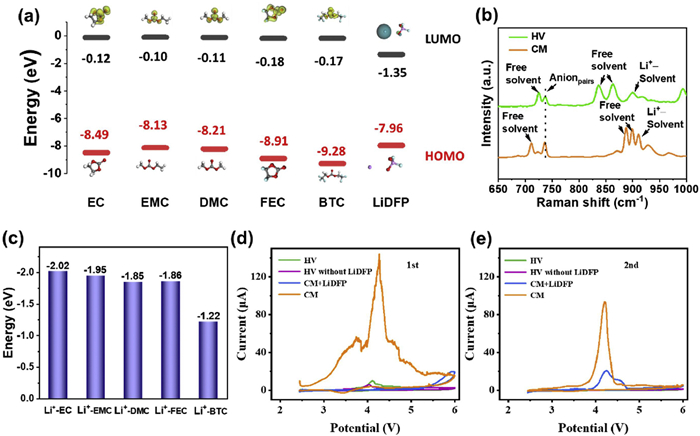
In this study, commercial electrolyte consists of 1 mol/L LiPF6 in ethylene carbonate (EC)/DMC/ethyl methyl carbonate (EMC) (1:1:1 by volume) and is named as CM electrolyte. Frontier molecular orbital calculations were performed for all solvents (Fig. 1a). EC, EMC and DMC present −8.49, −8.13, and −8.21 eV, respectively. Compared to three solvents of the CM electrolyte, FEC (−8.91 eV) and BTC (−9.28 eV) exhibit lower HOMO energy levels, indicating superior oxidation resistance and suitability for high–voltage condition. In contrast, the additive LiDFP possesses a higher HOMO value of −7.96 eV, which facilitates its preferential decomposition on the surface of NCM811 particles compared with FEC and BTC solvents, thereby promoting the formation of a LiF–rich CEI layer.
Figure 1
Figure 1.
HOMO and LUMO energy level of all solvents. (b) Raman spectra of HV and CM electrolytes. (c) Binding energy of Li+ and different solvents. CV curves of Li||steel cells with HV and CM electrolytes during 2.5–6.0 V at (d) 1st and (e) 2nd cycle.
Raman spectroscopy was conducted on both electrolytes. The CM electrolyte shows a relatively high-intensity peak corresponding to Li+–solvent coordination (921 cm-1) [39] in Fig. 1b In contrast, the modified HV electrolyte exhibits relatively high-intensity peaks of free solvents (720, 829, 872 cm-1), suggesting weak interaction between Li+ and solvents. Moreover, the peak of LiDFP (996 cm-1) was detected in Fig. S1 (Supporting information). Further binding energy calculations between Li+ and the solvents reveal weaker solvation of Li+ by the fluorinated solvents FEC and BTC than EC and EMC (Fig. 1c). This weak solvation structure implies that in the HV electrolyte, Li+ interacts more strongly with PF6- anions than in the CM electrolyte. Given the high fluorine content in PF6-, the HV electrolyte favors the formation of a LiF–enriched CEI.
Optical images of the two electrolytes (Fig. S2 in Supporting information) show that both are transparent and clear. Combustion tests were performed on the electrolytes (Fig. S3 in Supporting information and attached video). In the combustion test, conducted with 0.2 mL of each electrolyte, the HV formulation showed no sign of sustained ignition and self-extinguished instantaneously upon flame removal, yielding a self-extinguishing time of 0 s. In stark contrast, the CM electrolyte ignited after 6 s of flame exposure and continued to burn throughout the remainder of the 20 s test period.
To probe the role of individual components, two control electrolytes were introduced: HV-base without LiDFP and CM + LiDFP. Their linear sweep voltammetry (LSV)/cyclic voltammetry (CV) behaviors were compared with the standard HV and CM electrolytes. LSV measurements (Fig. S4 in Supporting information) show that the pristine CM electrolyte undergoes pronounced oxidation during the first cycle. This oxidation is mitigated upon addition of LiDFP, although an increased oxidative response is observed in the 6–6.5 V region. In contrast, the HV-based electrolytes exhibit superior anodic stability. While the HV-base formulation without LiDFP is slightly less oxidation-resistant than the HV electrolyte, it still outperforms both CM and CM+LiDFP, highlighting the inherent oxidative stability of the FEC/BTC solvent system. Meanwhile, these results suggest a synergistic effect between LiDFP and the FEC/BTC solvent system in imparting oxidation resistance, likely arising from the film-forming ability of LiDFP and the inherent oxidative stability of FEC/BTC.
CV analysis corroborates these findings. The CM electrolyte displays significant redox activity during the first cycle (Fig. 1d), which can be effectively suppressed by LiDFP addition, though residual redox features persist during 5.5–6 V. By comparison, the HV electrolyte shows markedly lower redox currents across the entire 2.5–6 V window, indicating both effective film-forming ability and robust oxidation resistance. Notably, for all four electrolytes, redox activity is substantially reduced in the second cycle (Fig. 1e and Fig. S5 in Supporting information), consistent with the formation of a passivating CEI layer after the initial activation.
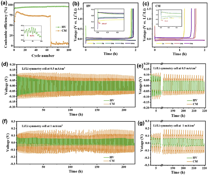
The lithium plating/stripping behavior was evaluated in Li||Cu half-cells using two different electrolytes. The Li||Cu cell employing the HV electrolyte exhibited a Coulombic efficiency (CE) of 96.3%, substantially higher than that of the cell with a commercial CM electrolyte (~74%) in Fig. 2a. Moreover, the lithium stripping duration in the HV-based cell remained around 1.9 h (Fig. 2b) during cycling, significantly longer than the ~1.6 h (Fig. 2c) observed for the CM electrolyte. Electrochemical performance was further assessed in Li||Li symmetric cells. At both 0.5 and 1 mA/cm2 current densities, cells with the HV electrolyte showed lower polarization (Figs. 2d and f). The corresponding voltage hysteresis values were 0.097 V at 0.5 mA/cm2 (Fig. 2e) and 0.11 V at 1 mA/cm2 (Fig. 2g). The high-current performance at 3 and 5 mA/cm2 have also been conducted. Li||Li cells using HV electrolyte run 120 h at 3 and 5 mA/cm2 (Fig. S6 in Supporting information). However, Li||Li cells incorporating the CM electrolyte exhibited pronounced polarization and could not withstand high current densities.
Figure 2
Figure 2.
(a) CE of Li stripping/plating in Li||Cu cells with HV and CM electrolytes at 0.5 mA/cm2 with a capacity of 1 mAh/cm2, and the corresponding discharge-charge curves with (b) HV and (c) CM electrolytes during cycling. Long-term cycling performance of Li||Li symmetric cells with HV and base electrolytes at (d) 0.5 mA/cm2 and (f) 1 mA/cm2. The enlarged voltage-time profiles corresponding to (e) 0.5 mA/cm2 and (g) 1 mA/cm2.
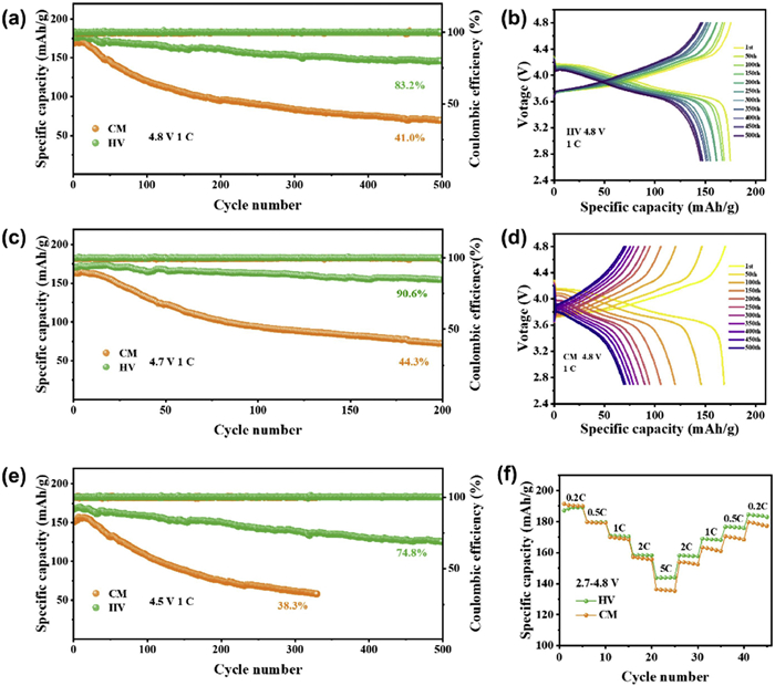
Li||NCM811 cells were assembled using the two electrolytes and subjected to cycling performance tests at 1 C. As shown in Fig. 3a, the cell employing the HV electrolyte retained 83.2% of its capacity after 500 cycles at an ultra-high cut-off voltage of 4.8 V, which is markedly higher than the 41.0% capacity retention of the cell with the CM electrolyte. Meanwhile, specific energy and median voltage of Li||NCM811 cell with HV CM electrolytes is dramastically higher than the CM-based counterpart during cycling (Fig. S7 in Supporting information). This demonstrates the excellent cycling stability of the HV electrolyte under high-voltage operation.
Figure 3
Figure 3.
Elctrochemical performance of Li||NCM811 cells. Long-cycle performance with HV and CM electrolytes at (a) 4.8 V, (c) 4.7 V, and (e) 4.5 V. (b, c) Potential-capacity curves for long-cycle tests using (b) HV and (d) CM electrolytes at 4.8 V. (f) Rate performance with both electrolytes at 4.8 V.
Charge-discharge profiles of the NCM811 cathode with both electrolyte at different cycle numbers are presented in Figs. 3b and d. Both the discharge voltage and the specific discharge capacity decrease progressively upon cycling, indicating continuous growth of polarization for CM-electrolyte NCM811 cathode (Fig. 3d). In contrast, the NCM811 cathode using the HV electrolyte exhibits a much slower decline in both voltage and specific capacity during cycling (Fig. 3b). Moreover, the dQ/dV curves of Li||NCM811 cell with HV electrolyte also display higher discharge potentials and lower polarization during cycling (Fig. S8 in Supporting information).
The cycling performance of CM with LiDFP and HV without LiDFP electrolytes have also been detected. The CM with LiDFP electrolyte exhibited an improvement of cycling performance than pristine CM electrolyte at 1 C during 2.7–4.8 V, with the capacity retention increasing from 86.3% to 98.1% after 50 cycles (Fig. S9 in Supporting information). Similarly, the FEC/BTC-based electrolyte demonstrated enhanced cycling performance upon the addition of LiDFP, rising from 95.3% to 96.9%. Notably, the HV electrolyte (FEC/BTC + LiDFP) achieved the higher capacity and cycling stability, indicating that the superior cycling performance arises from the synergistic effect of LiDFP and the FEC/BTC combination. NCM811 cell with a high-mass-loading of 6 mg/cm2 have also been tested at 1 C during 2.7–4.8 V. Even at high mass-loading, NCM811 cell using HV electrolyte still has superior cycling performance with an 88.1% retention after 50 cycles at 1 C (Fig. S10 in Supporting information). At high mass loading, the NCM811 cell using the CM electrolyte delivered a specific capacity of 193 mAh/g at 0.2 C, yet exhibited negligible capacity at 1 C.
Rate capability was also evaluated during 2.7–4.8 V. The NCM811 cathode with the HV electrolyte delivered discharge capacities of 190.57, 179.47, 169.71, 156.74, and 143.9 mAh/g at 0.2, 0.5, 1, 2, and 5 C, respectively (Fig. 3f). Notably, at the high current density of 5 C, the HV-based NCM811 cathode exhibited superior discharge capacity. Furthermore, after high-rate cycling, the HV-based cathode recovered its capacity upon returning to low current densities, whereas the CM-based cathode showed a marked capacity fade. These results indicate that the HV electrolyte offers significantly enhanced high-voltage stability compared with the commercial CM electrolyte.
Cycling performance was further evaluated at lower cut-off voltages of 4.7 and 4.5 V (Figs. 3c and e). The NCM811 cathodes with the HV electrolyte deliver capacity retention of 90.6% for 4.7 V after 200 cycles and 74.8% for 4.5 V after 500 cycles. The HV electrolyte again show significantly better cycling stability compared to those with the CM electrolyte (44.3% for 4.7 V, 38.3% for 4.5 V). Moreover, the charge-discharge profiles reveal that the HV-based Li||NCM811 cells experience slower voltage and capacity fade during cycling (Fig. S11 in Supporting information). The cycling performance of HV-based Li||NCM811 cells exhibits notable competitiveness when benchmarked against previously reported data in other studies during the past five years (Table S1 in Supporting information).
High-temperature cycling performance was also investigated (Fig. S12a in Supporting information). At 60 ℃, the NCM811 cathode with the HV electrolyte delivers an initial discharge capacity of 200.6 mAh/g at 1 C, substantially higher than the 162.0 mAh/g obtained with the CM electrolyte. After 100 cycles, the HV-based NCM811 cathode still maintains a discharge capacity of 145.4 mAh/g, outperforming the 123.9 mAh/g of the CM electrolyte counterpart. Furthermore, the NCM811 cathode with the HV electrolyte exhibits higher discharge voltages throughout cycling (Figs. S12b and c in Supporting information), indicating superior high-temperature performance.
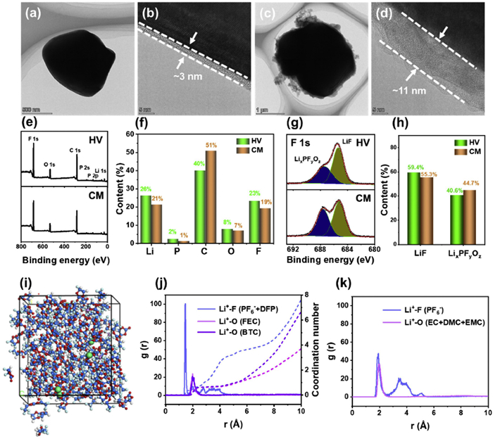
To elucidate the superior electrochemical performance of the HV electrolyte, corresponding microstructural characterization was conducted. First, the morphology of NCM811 electrodes cycled at 4.8 V for 200 cycles in both electrolytes was examined. SEM images reveal minimal differences in the overall electrode morphology between the two samples (Fig. S13 in Supporting information). However, TEM analysis provides clearer insights: The NCM811 cathode cycled in the HV electrolyte exhibits a uniform and thin CEI layer with a thickness of approximately 3 nm on the particle surface (Figs. 4a and b). In contrast, the cathode cycled in the CM electrolyte displays an irregular and non-uniform CEI (Fig. 4c and Fig. S14 in Supporting information), with a measured thickness of about 11 nm.
Figure 4
Figure 4.
TEM images of NCM811 electrode with (a, b) HV and (c, d) CM electrolytes after 200 cycles at 4.8 V. (e) Full and (g) F 1s XPS spectra of NCM811 electrode with HV and CM electrolytes after 200 cycles at 4.8 V. (f) Li, P, C, O, F element content base on full XPS spectra. (h) LiF and LixPFyOz content base on F 1s XPS spectra. Molecular dynamic simulation of both electrolytes. (i) Snapshots of HV electrolyte; Li+ radial distribution function of (j) HV and (k) CM.
XPS was performed on the surface of the cycled NCM811 cathodes. The HV electrolyte results in a surface richer in F and Li elements but lower in C content compared to the CM electrolyte (Figs. 4e and f). High-resolution F 1s spectra further indicates that the CEI formed in the HV electrolyte contains a significantly higher proportion of LiF (59.4% vs. 55.3%), confirming the formation of a LiF-rich interphase. In comparison, the CEI from the CM electrolyte shows higher C content and lower P and O signals, suggesting a predominantly organic-rich composition (Fig. 4f and Fig. S16 in Supporting information). Deconvolution of the Li 1s spectra confirms the presence of multiple components, including LiF, Li2CO3/ROCO2Li, and Li2O (Fig. S16) [29,40].
By combining TEM and XPS analysis, the superior high-voltage stability of the designed HV electrolyte is attributed to its inherent electrochemical robustness coupled with advantageous interfacial properties. Specifically, the fluorinated electrolyte facilitates the formation of a uniform, ultrathin, and LiF-rich CEI on the NCM811 surface (Fig. S17a in Supporting information), which stands in stark contrast to the thick, structurally heterogeneous and organic-rich CEI formed in CM electrolytes (Fig. S17b in Supporting information). This thin, homogeneous, and LiF-rich interphase collectively ensures the prolonged cycling stability of Li||NCM811 cells at 4.8 V.
Additionally, electrochemical impedance spectroscopy (EIS) measurements were carried out on the cycled cells (Fig. S18 in Supporting information). The HV electrolyte-based cell exhibits higher interfacial resistance, which is likely attributable to the more insulating nature of the LiF-rich CEI layer. A thin and uniform LiF-enriched layer presents a higher intrinsic resistance to electronic transport, whereas the more organic-rich CEI formed in the CM electrolyte offers lower electronic resistance. Importantly, despite its higher electronic resistance at the interface, such a uniform LiF-enriched layer may function as a superior passivation film. In contrast, the thicker CEI formed in the CM electrolyte, despite its lower interfacial impedance, is more organic-rich and irregular in structure. This morphology may fail to inhibit continuous parasitic reactions, leading to progressive interfacial degradation upon extended cycling.
To further investigate the mechanism behind the formation of a LiF-rich CEI layer by the HV electrolyte, molecular dynamics (MD) simulations were carried out using Materials Studio software. The simulation results for both electrolytes are presented in Fig. 4i and Fig. S19 (Supporting information), respectively. Given the low concentration of Li+ ions relative to the bulk solvent, Li+ ions are dispersed within the solvent matrix. By zooming into the local coordination environment around Li+ ions based on the MD trajectories, it is observed that in the HV electrolyte, Li+ ions are primarily surrounded by BTC, FEC solvent molecules, and PO2F2- (DFP-) anions (Fig. S20a in Supporting information). In contrast, Li+ ions in the CM electrolyte are coordinated mainly by EC, DMC, and EMC solvent molecules (Fig. S20b in Supporting information).
Radial distribution functions (RDFs) derived from the MD simulations provide further insight into the Li+ solvation structure. In the HV electrolyte, PF6- and DFP- anions are located closer to Li+ ions (Fig. 4j), while solvent molecules reside at relatively longer distances (Fig. 4k). Meanwhile, coordination numbers of Li+-solvent (Li+-O (FEC) and Li+-O (BTC)) is lower than that of Li+-anion (Li+-F (PF6-+DFP)) based on Table S2 (Supporting information) and Fig. 4j. This configuration indicates a weakly solvated structure, in which a greater number of PF6- and DFP- anions participate in the interfacial reactions during CEI formation, leading to the generation of a CEI rich in LiF (59.4% according to XPS results in Figs. 4e-h). Conversely, in the CM electrolyte, the distances between Li+ ions and PF6- anions are comparable to those between Li+ ions and solvent molecules. As a result, fewer PF6- anions are involved in CEI formation, yielding a CEI with lower LiF content (55.3% based on XPS data from Figs. 4e-h).
In this study, an all-fluorinated electrolyte system comprising fluorinated solvents, lithium salts, and additives was designed to stabilize the high-voltage (4.8 V) cycling performance of Li||NCM811 cells. Compared with current commercial electrolyte, the developed fluorinated electrolyte enabled the Li||NCM811 cells to retain 83.2% of its initial capacity after 500 cycles at 1 C under an ultra-high cut-off voltage of 4.8 V, significantly surpassing the 41.0% retention achieved with the commercial electrolyte. The fluorinated electrolyte also demonstrates superior compatibility with the lithium-metal anode compared to conventional commercial electrolytes. Meanwhile, the fluorinated design endowed the electrolyte with intrinsic flame-retardant properties. Further mechanistic analysis reveals that the enhanced high-voltage stability originates from both intrinsic electrochemical stability and favorable interfacial characteristics. First, the fluorinated solvents exhibit lower highest occupied molecular orbital (HOMO) energy levels, endowing the electrolyte with inherently superior oxidation resistance. More importantly, the fluorinated electrolyte promotes the formation of a uniform and thin (~3 nm) cathode-electrolyte interphase (CEI) on the NCM811 surface, in sharp contrast to the thick and irregular CEI (~11 nm) generated by the commercial electrolyte. Molecular dynamics simulations indicate that the fluorinated electrolyte facilitates a weakly solvated structure, in which the primary solvation sheath of Li+ ions is enriched with PF6- and DFP- anions. This unique solvation environment favors the preferential decomposition of fluorine-containing species during cycling, leading to a LiF-rich CEI. The combined effects of a thin, uniform, and LiF-enriched CEI collectively contribute to the stable long-term cycling of Li||NCM811 batteries at 4.8 V.
The authors declare that they have no known competing financial interests or personal relationships that could have appeared to influence the work reported in this paper.
Acknowledgments
The authors gratefully acknowledge the financial support from Shaanxi Natural Science Basic Research Program (Nos. 2025JC-YBMS-073 and 2025JC-YBQN-221) and China College Student Innovation and Entrepreneurship Training Program (No. 202510705064).
Supplementary materials
Supplementary material associated with this article can be found, in the online version, at doi:10.1016/j.cclet.2026.112802.
[1]
J. Zhou, H. Wang, Y. Yang, et al., Adv. Energy Mater. 15 (2025) 2502654. doi: 10.1002/aenm.202502654
[2]
X. Zeng, J. Chen, Z. Zhou, et al., Energy Storage Mater. 82 (2025) 104553. doi: 10.1016/j.ensm.2025.104553
Figure 1
HOMO and LUMO energy level of all solvents. (b) Raman spectra of HV and CM electrolytes. (c) Binding energy of Li+ and different solvents. CV curves of Li||steel cells with HV and CM electrolytes during 2.5–6.0 V at (d) 1st and (e) 2nd cycle.
Figure 2
(a) CE of Li stripping/plating in Li||Cu cells with HV and CM electrolytes at 0.5 mA/cm2 with a capacity of 1 mAh/cm2, and the corresponding discharge-charge curves with (b) HV and (c) CM electrolytes during cycling. Long-term cycling performance of Li||Li symmetric cells with HV and base electrolytes at (d) 0.5 mA/cm2 and (f) 1 mA/cm2. The enlarged voltage-time profiles corresponding to (e) 0.5 mA/cm2 and (g) 1 mA/cm2.
Figure 3
Elctrochemical performance of Li||NCM811 cells. Long-cycle performance with HV and CM electrolytes at (a) 4.8 V, (c) 4.7 V, and (e) 4.5 V. (b, c) Potential-capacity curves for long-cycle tests using (b) HV and (d) CM electrolytes at 4.8 V. (f) Rate performance with both electrolytes at 4.8 V.
Figure 4
TEM images of NCM811 electrode with (a, b) HV and (c, d) CM electrolytes after 200 cycles at 4.8 V. (e) Full and (g) F 1s XPS spectra of NCM811 electrode with HV and CM electrolytes after 200 cycles at 4.8 V. (f) Li, P, C, O, F element content base on full XPS spectra. (h) LiF and LixPFyOz content base on F 1s XPS spectra. Molecular dynamic simulation of both electrolytes. (i) Snapshots of HV electrolyte; Li+ radial distribution function of (j) HV and (k) CM.


 DownLoad:

 下载:


 下载:

