Citation:
Jian Cai, Ying Zhou, Han Zhu. Atomic-scale homogeneity in an ordered high-entropy intermetallic drives efficient nitrate reduction and high-performance Zn–NO3− battery[J]. Chinese Chemical Letters,
2026, 37(12): 112775.
doi:
10.1016/j.cclet.2026.112775
Atomic-scale homogeneity in an ordered high-entropy intermetallic drives efficient nitrate reduction and high-performance Zn–NO3− battery
English
Atomic-scale homogeneity in an ordered high-entropy intermetallic drives efficient nitrate reduction and high-performance Zn–NO3− battery
Key Laboratory of Synthetic and Biological Colloids, Ministry of Education, School of Chemical and Material Engineering, Jiangnan University, Wuxi 214122, China
b.
College of Textile Science and Engineering (International Institute of Silk), Zhejiang Sci-Tech University, Hangzhou 310018, China
Received Date:
04 February 2026 Accepted Date:
14 April 2026 Revised Date:
08 April 2026 Available Online:
15 December 2026
Abstract:
The electrochemical reduction of nitrate to ammonia offers a sustainable route for simultaneous wastewater remediation and decentralized NH3 production, yet it requires advanced catalysts capable of precisely managing the complex multi-step reaction pathway. Herein, we report the rational design of a high-entropy intermetallic (HEI), (FeCoNiCu)6Sn5, which serves as a highly efficient and exceptionally stable electrocatalyst for nitrate-to-ammonia conversion. The HEI catalyst achieves a remarkable NH3 Faradaic efficiency of 97.4% and a high yield rate of 23.3 mg h−1 mgcat−1, maintaining robust stability over 150 h of continuous operation. Mechanistic investigations reveal that this outstanding performance stems from an ingenious synergistic division of site-specific functions: The Cu component promotes nitrate adsorption and initial reduction to nitrite, the Fe/Co/Ni components enhance subsequent hydrogenation kinetics, and the Sn component effectively suppresses the competing hydrogen evolution reaction (HER). When integrated into a practical Zn–NO3− battery system, the (FeCoNiCu)6Sn5 cathode simultaneously delivers a peak power density of 4.32 mW/cm2 alongside continuous ammonia production. This work establishes a versatile and powerful platform based on HEI for the precise construction of multicomponent catalysts, offering a new frontier for sustainable electrochemical synthesis.
The sustainable production of ammonia (NH3), an indispensable fertilizer precursor and carbon-free energy carrier, urgently requires alternatives to the energy-intensive Haber-Bosch process [1–4]. A compelling alternative is the electrocatalytic nitrate reduction reaction (NO3RR), which is particularly attractive because it simultaneously addresses two major global issues: The need for NH3 synthesis and remediation of widespread nitrate water contaminant. NO3RR represents a multi-step, 8-electron transfer process (NO3− to NH3) that requires advanced catalysts capable of precisely coordinating nitrate adsorption, its reduction to nitrite (NO2−), and the subsequent hydrogenation of NO2− to NH3 [5–8]. Efficiently achieving high NH3 selectivity and high reaction rates necessitates catalytic active sites capable of fine-tuning *H adsorption and N-O bond activation energies along the entire reaction pathway, while suppressing the competing hydrogen evolution reaction (HER) [9–12].
Intermetallic compounds (IMCs) characterized by their long-range atomic ordering, fixed stoichiometry and well-defined active sites, have emerged as promising candidates to meet this demand [13]. Their enthalpy-driven formation, arising from strong d–d orbital hybridization, endows them with inherent structural robustness and predictable electronic structures compared to disordered alloys. At the nanoscale, this ordered arrangement leads to sharper site specificity, reduced energy barriers for specific steps, and improved operational durability [14–16]. However, traditional binary IMCs offer limited compositional flexibility, restricting their ability to rationally optimize multi-step reaction pathways or leverage multi-metal synergy.
High-entropy intermetallics (HEIs) offer a powerful solution to overcome the compositional limitations. of traditional IMCs. By incorporating multiple functionally distinct elements into a single, structurally ordered sublattice, HEIs successfully couple the advantages of long-range atomic ordering with the electronic tunability afforded by high-entropy mixing [17–20]. Crucially, the homogeneous atomic distribution within the ordered lattice ensures that each metal atom participates in well-defined local environments, allowing genuine cooperative interactions rather than the random, heterogeneous site distributions often seen in high-entropy alloys (HEAs) [21–24]. This combination provides a unique platform for precisely tailoring adsorption energetics, modulating the d-band center, and creating or coupling specific catalytic motifs. Recent examples, from Pt4FeCoCuNi HEIs with optimized intermediate adsorption to NiFeCuGaGe HEIs achieving atom-pair isolation, highlight how ordered high-entropy lattices unlock synergistic active-site functionalities that disordered alloys cannot achieve [25,26].
Inspired by these insights, we sought to leverage atomic ordering as the foundation while expanding the compositional space through high-entropy design. Herein, we report a rationally engineered HEI electrocatalyst, (FeCoNiCu)6Sn5, built upon the robust Cu6Sn5-type crystal framework to ensure complete atomic homogeneity and long-range order. By strategically incorporating multiple transition metals into the ordered sublattice, we successfully create a multifunctional active environment where each metal plays a distinct, cooperative role. Cu sites preferentially facilitate NO3− adsorption and reduction to NO2−, Fe/Co/Ni sites drive efficient hydrogenation steps, and Sn sites suppress the competing HER. Owing to this synergistic interplay within the structurally ordered high-entropy lattice, the (FeCoNiCu)6Sn5 HEI catalyst exhibits exceptional NO3RR performance, achieving a high NH3 yield rate of 23.3 mg h−1 mgcat−1 and a high NH3 Faradaic efficiency (FE) of 97.4%, alongside outstanding long-term stability over 150 h. This work establishes HEIs as a versatile and powerful platform for designing structurally homogeneous, compositionally diverse, and functionally synergistic catalytic sites. Beyond NO3RR, this strategy provides a general blueprint for tuning multi-step electrochemical reactions through high-entropy–driven electronic modulation within atomically ordered frameworks.
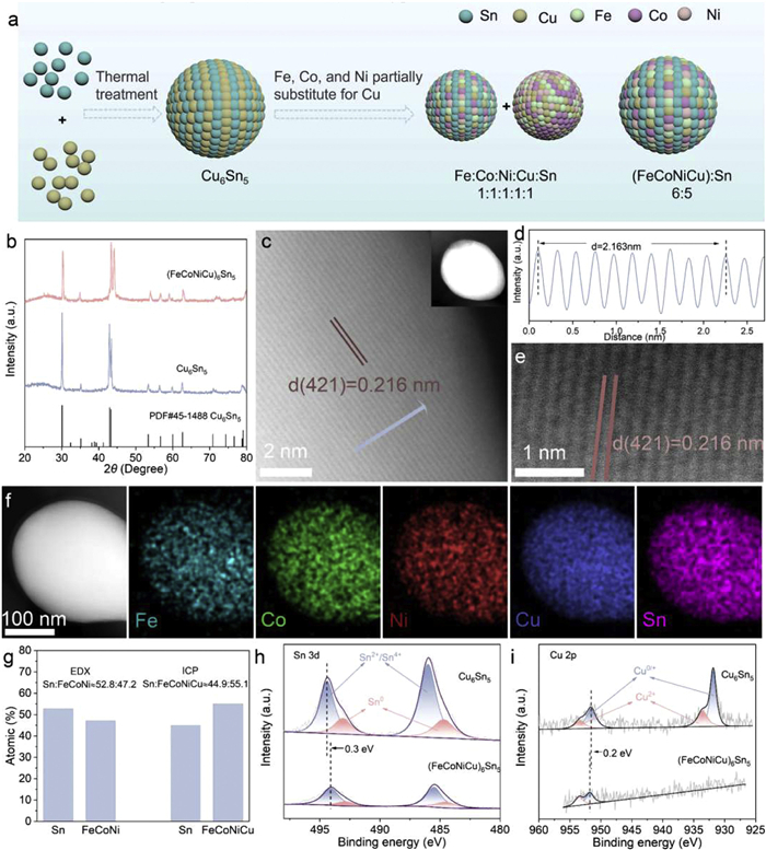
As illustrated in Fig. 1a, Cu6Sn5-type catalysts were synthesized via electrospinning followed by carbonization. To construct the HEI phase, Fe, Co, and Ni, chosen for their chemical similarity to Cu, were incorporated into the Cu6Sn5 lattice. By precisely tuning the metal stoichiometry, two distinct materials were obtained: A phase-separated FeCoNiCuSn HEA with an approximate Fe:Co:Ni:Cu:Sn ratio of 1:1:1:1:1, and a single-phase (FeCoNiCu)6Sn5 type HEI with a total (Fe+Co+Ni+Cu):Sn ratio of ≈ 6:5.
Figure 1
Figure 1.
(a) Schematic illustration for the preparation of Cu6Sn5-type intermetallic compounds. (b) XRD patterns of (FeCoNiCu)6Sn5 and Cu6Sn5 supported on CNFs. (c) HAADF-STEM image of a (FeCoNiCu)6Sn5 NP. (d) The intensity profiles along the bule arrow marked in Fig. 1c. (e) Atomic resolution HAADF-STEM image of a (FeCoNiCu)6Sn5 NP. (f) STEM-EDX mapping images of a (FeCoNiCu)6Sn5 NP. (g) Compositional analysis obtained from ICP-MS and EDX. (h) Sn 3d and (i) Cu 2p XPS spectra of (FeCoNiCu)6Sn5 and Cu6Sn5 supported on CNFs.
As shown in Fig. 1b, both (FeCoNiCu)6Sn5 and Cu6Sn5 crystallize in the monoclinic Cu6Sn5 intermetallic structure (PDF #45-1488, space group *C2/c*), distinct from systems consisting solely of the metallic elements Fe, Co, Ni, Cu, and Sn (Fig. S1 in Supporting information). The diffraction peaks at 30.1°, 35.1°, 43.0°, and 43.3° correspond to the (221), (402), (204), and (422) crystal planes of monoclinic (FeCoNiCu)6Sn5 phase. In contrast, the FeCoNiCuSn sample exhibits a mixed-phase structure containing both the (FeCoNiCu)6Sn5 HEI phase and FCC solid solution phase (Fig. S2 in Supporting information).
Field-emission scanning electron microscopy (FE-SEM) images (Fig. S3 in Supporting information) show that the carbon nanofibers (CNFs) exhibit a smooth, continuous fiber morphology. This interconnected CNF network serves as a conductive framework that promotes effective mass transport and charge transfer during electrocatalytic reactions. Atomic-resolution aberration-corrected high-angle annular dark-field scanning transmission electron microscopy (HAADF-STEM) was employed to investigate the atomic arrangement of the multicomponent intermetallic structure. The measured interplanar spacing of 2.16 Å corresponds to the (421) plane, and the averaged interplanar spacings together with atomic-scale image confirm the formation of a well-defined crystal lattice (Figs. 1c–e and Fig. S4 in Supporting information). STEM-EDS elemental mapping (Fig. 1f) reveals a homogeneous spatial distribution of all metallic constituents (Fe, Co, Ni, Cu, and Sn), with no detectable phase segregation. To eliminate artefacts arising from the Cu TEM grid, the elemental composition was recalculated after excluding the Cu signal (Fig. 1g). The resulting Sn:(Fe+Co+Ni) ratio of ≈ 1.12 is in excellent agreement with the theoretical stoichiometric ratio of 10:9 (≈1.11). Moreover, inductively coupled plasma mass spectrometry (ICP-MS) further shows that the Sn:(Fe+Co+Ni+Cu) atomic ratio is ≈ 1:1.23 (Table S1 in Supporting information), closely matching the theoretical 5:6 stoichiometric ratio (1:1.20) for the (FeCoNiCu)6Sn5 HEI. The consistent structural and compositional evidence obtained from FE-SEM, HAADF-STEM, STEM-EDS, and ICP-MS unambiguously confirm the successful synthesis of (FeCoNiCu)6Sn5 HEI.
X-ray photoelectron spectroscopy (XPS) was employed to investigate the electronic interactions in the (FeCoNiCu)6Sn5 HEI in comparison with the Cu6Sn5. In the Sn 3d XPS spectra (Fig. 1h), Cu6Sn5 exhibits characteristic doublet peaks at 486.0 eV (Sn2+/4+ 3d5/2) and 494.4 eV (Sn2+/4+ 3d3/2), along with metallic Sn0 peaks at 484.7 eV and 493.1 eV [27–30]. For the (FeCoNiCu)6Sn5 HEI, the Sn2+/4+ peaks shift negatively to 485.7 and 494.1 eV (−0.3 eV), indicating that the atomic substitution by Ni, Fe and Co promotes electron accumulation at Sn sites and increases the local electron density surrounding Sn [31]. In the Cu 2p spectra (Fig. 1i), the Cu6Sn5 reference sample displays dominant metallic Cu0/+ peaks at 931.8 eV (Cu 2p3/2) and 951.6 eV (Cu 2p1/2), accompanied by weak Cu2+ peak at 933.6 and 953.3 eV [32–35]. In contrast, the (FeCoNiCu)6Sn5 HEI displays a slight positive shift to 953.5 and 951.8 eV (+0.2 eV), suggesting partial valence electron donation from Cu to neighboring transition-metal species within the high-entropy framework [36,37]. These results collectively demonstrate that the introduction of multiple transition metals effectively modulates the electronic structure of the (FeCoNiCu)6Sn5 HEI, underpinning its modified chemical environment relative to Cu6Sn5.
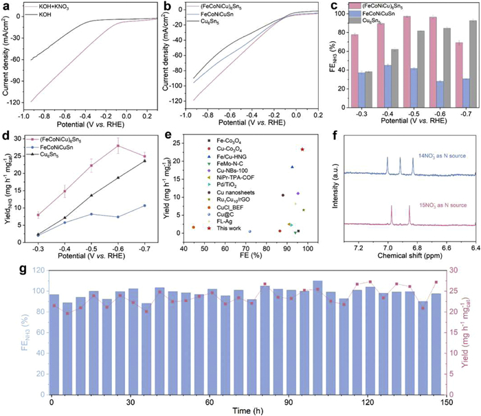
The electrocatalytic NO3RR performance was evaluated in an H-type cell equipped with a three-electrode system (Fig. S5 in Supporting information) using Ar-saturated 0.1 mol/L KOH electrolyte containing 0.1 mol/L KNO3 as the electrolyte. As shown in Fig. 2a, linear sweep voltammetry (LSV) measurements of the (FeCoNiCu)6Sn5 HEI catalyst were recorded in 0.1 mol/L KOH electrolytes with and without 0.1 mol/L NO3−. The pronounced increase in current density upon the introduction addition of nitrate clearly indicates the onset of NO3RR, distinguishing it from the HER. Fig. 2b compares the LSV curves of the Cu6Sn5 intermetallic, FeCoNiCuSn HEA and the (FeCoNiCu)6Sn5 HEI. Among the three, the Cu6Sn5 exhibits the lowest current density over the entire potential range. Partial substitution of Cu with Fe, Co, and Ni to form the phase-separated FeCoNiCuSn HEA leads to a clear increase in current density, indicating improved electrocatalytic activity. Further composition optimization and the formation of the (FeCoNiCu)6Sn5 HEI yield the highest current density among all samples. This trend is further corroborated by the partial NH3 current density results (Fig. S6 in Supporting information), in which the (FeCoNiCu)6Sn5 HEI also outperforms the other catalysts, highlighting the advantageous role of the ordered intermetallic structure in accelerating the reaction kinetics. To further investigate the reaction kinetics, Tafel slopes was performed on the iR-corrected LSV curves. As shown in Fig. S7 (Supporting information), the (FeCoNiCu)6Sn5 HEI catalyst exhibits a Tafel slope of 366 mV/dec, markedly lower than those of the FeCoNiCuSn HEA (410 mV/dec) and Cu6Sn5 (544 mV/dec). These results indicate that the atomic-scale orchestration and long-range homogeneity inherent to the HEI phase significantly lower the kinetic barrier, thereby fostering a more efficient pathway for the NO3RR.
Figure 2
Figure 2.
(a) LSV curves of (FeCoNiCu)6Sn5 HEI normalized to the geometric area in 0.1 mol/L KOH with and without 0.1 mol/L KNO3. (b) LSV curves, (c) FENH3 and (d) YieldNH3 of the Cu6Sn5, FeCoNiCuSn HEA and the (FeCoNiCu)6Sn5 HEI in 0.1 mol/L KOH containing 0.1 mol/L KNO3. (e) Comparison of the NO3RR performances of (FeCoNiCu)6Sn5 HEI with recently reported state-of-the-art electrocatalysts. (f) 1H NMR spectra of (FeCoNiCu)6Sn5 HEI using 14NO3− and 15NO3− as N sources. (g) Long-term stability test of (FeCoNiCu)6Sn5 HEI performed at −0.5 V vs. RHE.
Product selectivity was evaluated over a potential range from −0.3 V to −0.7 V (vs. RHE) through chronoamperometric tests lasting 1 h at each potential. The concentrations of NH3 and NO2− in the electrolyte were quantified using UV–vis spectrophotometry (Figs. S8 and S9 in Supporting information). As depicted in Fig. 2c, the Cu6Sn5 shows the lowest NH3 Faradaic efficiency (FENH3) of 38.4% at −0.3 V, followed by a gradual increase to 81.8% at −0.7 V. Correspondingly, the FENO2- decreases from 42% to 6.2%, suggesting insufficient hydrogenation ability at low potentials and improved performance only at more negative potentials. In contrast, the introduction of Fe, Co, and Ni into the FeCoNiCuSn substantially promotes the hydrogenation of NO2− intermediates. As shown in Fig. S10 (Supporting information), the FENO2- remains below 5% across the entire tested potential window from −0.3 V to −0.7 V, confirming the enhanced hydrogenation capability conferred by these transition metals. However, this compositional modification also intensifies the competing HER, with FEH2 remaining above 50% across the entire tested potential window. Consequently, the maximum FENH3 of the HEA is limited to only 45.2% at −0.4 V, underscoring the challenge of balancing hydrogenation activity with HER suppression.
Remarkably, the (FeCoNiCu)6Sn5 HEI catalyst achieves consistently stable and high NO3RR selectivity, maintaining FENH3 above 90% from −0.4 V to −0.6 V. A peak FENH3 of 97.4% is achieved at −0.5 V, significantly outperforming the values of the FeCoNiCuSn HEA (41.8%) and Cu6Sn5 (81.8%). This superior selectivity highlights the critical role of the ordered HEI structure in establishing an optimized atomic environment for efficient nitrate-to-ammonia conversion. Furthermore, the (FeCoNiCu)6Sn5 delivers an outstanding NH3 yield rate across the entire potential range from −0.3 V to −0.7 V, with a maximum value of 23.3 mg h−1 mgcat−1 at −0.6 V (Fig. 2d). The (FeCoNiCu)6Sn5 catalyst exhibits superior performance—achieving a 97.4% FENH3 and an NH3 yield of 23.3 mg h−1 mgcat−1—surpassing most state-of-the-art electrocatalysts benchmarked in recent literature (Fig. 2e and Table S2 in Supporting information).
To investigate the influence of active site density, control experiments were conducted by synthesizing (FeCoNiCu)6Sn5/CNF catalysts with total metal salt loadings of 0.55 and 2.2 mmol, corresponding to 0.5 times and 2 times the loading of the HEI catalyst (1.1 mmol), respectively. The NO3RR performance of these variants was subsequently evaluated under identical experimental conditions to ensure a direct comparison. For the low-loading HEI sample (HEI-0.55), although a high NH3 FE of 94.5% was maintained, the NH3 yield was limited to 19.0 mg h−1 mgcat−1 at −0.6 V, with a corresponding current density of 70.6 mA/cm2 at −0.7 V (Fig. S11 in Supporting information). This reduction in yield is primarily attributed to the sparse distribution of active sites within the CNF matrix. Conversely, the high-loading variant (HEI-2.2) exhibited a current density of 94.8 mA/cm2 and an FENH3 of 95.5%, yet the NH3 yield (34.4 mg h−1 mgcat−1) failed to scale linearly with the doubled metal precursor concentration. In comparison, the standard HEI-1.1 catalyst achieved an optimal balance, delivering an FENH3 of 96.5%, a current density of 85.8 mA/cm2, and a superior yield of 27.9 mg h−1 mgcat−1. These results demonstrate that while FENH3 remains robust across the tested loading range, the HEI-1.1 configuration maximizes the synergy between catalytic productivity and cost-effectiveness, serving as the optimal architecture for subsequent investigations.
Electrochemical impedance spectroscopy (EIS) measurements (Fig. S12 in Supporting information) reveal that the (FeCoNiCu)6Sn5 HEI exhibits the smallest charge transfer resistance (Rct) of 2.7 Ω, compared with 3.0 Ω for the FeCoNiCuSn HEA and 5.6 Ω for the Cu6Sn5, indicating more efficient charge transfer at the electrode–electrolyte interface. In addition, the electrochemically active surface area (ECSA), determined from the double layer capacitance (Cdl), reveals that the (FeCoNiCu)6Sn5 and FeCoNiCuSn possess similarly high Cdl values (155 and 150 mF/cm2, respectively), both substantially exceeding that of the Cu6Sn5 (110 mF/cm2) (Fig. S13 in Supporting information). This indicates that both multicomponent catalysts offer a higher density of accessible active sites compared to the Cu6Sn5 catalyst. A series of control experiments were performed to verify the origin of the produced NH3 (Figs. S14 and S15 in Supporting information). Negligible NH3 was detected under the following conditions: (1) In 0.1 mol/L KOH without NO3− at −0.5 V, (2) in 0.1 mol/L KOH with 0.1 mol/L KNO3 at open-circuit potential (OCP), and (3) using CNFs as the working electrode at −0.5 V. To further confirm the nitrogen source, isotopic labeling experiments using 15NO3− and 14NO3− were performed. The resulting 15NH4+ and 14NH4+ products were analyzed by 1H nuclear magnetic resonance (NMR) spectroscopy, displaying the characteristic doublet and triplet signals, respectively, thereby unambiguously demonstrating that NH3 originates from the electroreduction of NO3− (Fig. 2f and Fig. S16 in Supporting information). The (FeCoNiCu)6Sn5 HEI catalyst also demonstrates excellent operational stability. During a 150-hour chronoamperometry test at −0.5 V (Fig. 2g), the current density remained stable above 90%, and the NH3 yield was maintained above 20 mg h−1 mgcat−1. The post-catalytic evaluations, including XRD, XPS, and HR-TEM (Figs. S17–S19 in Supporting information), confirm that the (FeCoNiCu)6Sn5 HEI catalyst retains its morphology and ordered structure, demonstrating the exceptional robustness and phase stability of the HEI system under long-term electrocatalytic operation.
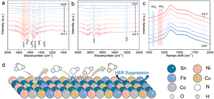
In situ attenuated total reflection-Fourier transform infrared spectroscopy (ATR-FTIR) were performed to gain deeper insights into the NO3RR mechanism. Infrared signals ranging from 4000 cm−1 to 1000 cm−1 were collected under applied potential from 0.1 V to −0.6 V, as well as at OCP. As displayed in Figs. 3a and b, no discernible signals are detected at OCP. Upon applying increasingly negative potentials, several characteristic intermediate-related peaks gradually appear. In the ATR-FTIR spectra of (FeCoNiCu)6Sn5 HEI in the range of 1800–1200 cm−1 (Fig. 3a) and 4000–3000 cm−1 (Fig. 3b), the peaks located at ~3450 cm−1 and 1640 cm−1 correspond to the O–H stretching and bending mode of water, respectively [38–40]. This indicates that water participates in the reduction and acts as the role of *H donor through water dissociation. The emergence of a clear N–H stretching band at 3740 cm−1, together with the characteristic peaks of –NH2 at 1430 and 1420 cm−1, confirm the formation of NH3 [9,41–43]. Furthermore, the gradual increase in peak intensity as the potential shifts from 0.1 V to −0.6 V suggest the enhanced NH3 production. A pair of characteristic peaks located at 1530 and 1340 cm−1 can be assigned to the asymmetric and symmetric vibration modes of absorbed NO2− intermediates, while the peak at 1510 cm−1 corresponds to the bending vibration of N–O–H species [9,44,45].
Figure 3
Figure 3.
(a, b) In situ ATR-FTIR spectra of (FeCoNiCu)6Sn5 HEI in 0.1 mol/L KOH with 0.1 mol/L KNO3. (c) In-situ Raman spectra of (FeCoNiCu)6Sn5 HEI in 0.1 mol/L KOH with 0.1 mol/L KNO3. (d) Reaction pathway on (FeCoNiCu)6Sn5 HEI.
As shown in the Raman spectra (Fig. 3c), the characteristic peak of NO3− at 1056 cm−1 intensifies from OCP to more cathodic applied potentials, indicating enhanced adsorption of nitrate on the catalyst surface [46,47]. As the potential is further shifted negatively, the intensity of the NO3− peak gradually diminishes, which is attributed to its progressive reduction into nitrogen-containing intermediates. In addition, a new peak emerges at 1156 cm−1, corresponding to the symmetric N–H stretching vibration of –NH2 species, suggesting the formation of partially hydrogenated nitrogen intermediates along the reaction pathway [42,48].
Based on comprehensive electrochemical and in situ spectroscopic data, a site-specific catalytic mechanism is proposed for the (FeCoNiCu)6Sn5 HEI, integrating the distinct functions of its constituent elements into a coherent reaction pathway (Fig. 3d). Within the Sn-modulated electronic framework, Cu sites serve as the primary centers for nitrate adsorption and initial activation. Adjacent Fe, Co, and Ni atoms, incorporated into the ordered lattice, significantly enhance the local concentration of reactive hydrogen species, thereby accelerating the hydrogenation of nitrogen-oxygen intermediates. This functional synergy directs the reaction along an efficient path: Adsorbed *NO3 is progressively deoxygenated to *NO2 and then to *NO. The key hydrogenation steps, transforming *NO to *NOH, followed by further reduction through *N, *NH, and *NH2 intermediates, are facilitated by the Fe/Co/Ni sites, while the Sn-rich environment concurrently suppresses the competing hydrogen evolution [49].
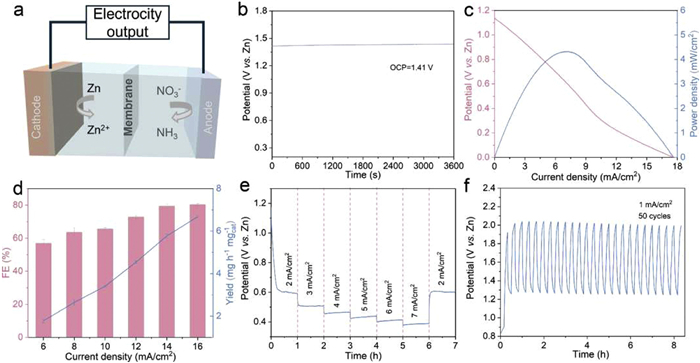
To demonstrate the practical application potential, a Zn–NO3− battery was constructed using a Zn plate as the anode in 3 mol/L KOH and the (FeCoNiCu)6Sn5 HEI electrocatalyst as the NO3− reduction cathode in 0.1 mol/L KOH containing 0.1 mol/L KNO3 (Fig. 4a). The resulting device delivered a stable OCP of 1.41 V vs. Zn (Fig. 4b). Discharge polarization measurements (Fig. 4c) further confirmed that the (FeCoNiCu)6Sn5‐based device achieved a peak power density of 4.32 mW/cm2 at 0.62 V. The peak power density of the (FeCoNiCu)6Sn5-based Zn–NO3− battery not only remains competitive with but frequently surpasses those of recently reported systems evaluated under comparable non-optimized cell configurations [50–52]. To verify its dual functionality, simultaneous NH3 production and power generation, the FENH3 and NH3 yield were quantified under increasing discharge current densities (Fig. 4d). Remarkably, even at a high current density of 16 mA/cm2, the battery maintained a high FENH3 of 80.3% and an NH3 yield rate of 6.68 mg h−1 mgcat−1. Galvanostatic discharge profiles revealed stable operating potential across current densities from 2 mA/cm2 to 7 mA/cm2 (Fig. 4e). Moreover, the device demonstrated excellent cycling durability, showing negligible performance decay over 50 cycles at 1 mA/cm2 (Fig. 4f). Collectively, these results highlight the promising performance of the (FeCoNiCu)6Sn5‐based Zn–NO3− battery as an integrated energy conversion system, capable of highly efficient nitrate‐to‐ammonia conversion coupled with simultaneous electricity generation.
Figure 4
Figure 4.
(a) Schematic illustration of the Zn-NO3− battery assembled with the (FeCoNiCu)6Sn5 HEI cathode. (b) OCP curve of the Zn-NO3− battery using the (FeCoNiCu)6Sn5 HEI cathode. (c) Polarization curves and corresponding power density of the Zn-NO3− battery. (d) NH3 yield and FENH3 for the Zn-NO3− battery at varied discharging current densities. (e) Galvanostatic discharge curves at different current densities. (f) Charge-discharge cycling curves of the Zn-NO3− battery at 1 mA/cm2.
In summary, we have successfully synthesized a high-entropy intermetallic compound (FeCoNiCu)6Sn5via electrospinning and carbonization for efficient electrocatalytic NO3RR. The optimized catalyst achieves exceptional performance with a peak NH3 FE of 97.4% at −0.5 V vs. RHE and a remarkable yield rate of 23.3 mg h−1 mgcat−1 at −0.6 V vs. RHE, while maintaining stable operation without performance degradation over 150 h of continuous testing. Through systematic comparison with reference catalysts, we identify a synergistic division of functions: Cu sites facilitate nitrate adsorption and its initial reduction to nitrite, partial substitution with Fe, Co, and Ni enhances subsequent hydrogenation steps to improve ammonia selectivity, while Sn effectively suppresses the competing hydrogen evolution reaction. Furthermore, the practical applicability of (FeCoNiCu)6Sn5 is demonstrated in a Zn–NO3− battery system, achieving a peak power density of 4.32 mW/cm2 alongside continuous ammonia production. This work provides a feasible strategy for rational design of highly efficient ordered intermetallic catalysts based on non-precious elements, opening avenues for sustainable nitrogen cycling and integrated energy-chemical conversion systems.
CRediT authorship contribution statement
Jian Cai: Writing – original draft, Investigation, Formal analysis, Data curation. Ying Zhou: Resources, Methodology. Han Zhu: Writing – review & editing, Supervision, Project administration, Investigation, Funding acquisition, Conceptualization.
Declaration of competing interest
The authors declare that they have no known competing financial interests or personal relationships that could have appeared to influence the work reported in this paper.
Acknowledgments
This study was supported by the National Natural Science Foundation of China (NSFC) (Nos. 52573323, 52273058), the Natural Science Foundation of Jiangsu Province (No. BK20220156), and the Fundamental Research Funds for the Central Universities. The authors would also like to thank the Central Laboratory, School of Chemical and Material Engineering.
Supplementary materials
Supplementary material associated with this article can be found, in the online version, at doi:10.1016/j.cclet.2026.112775.
[1]
L. Wang, Z. Wang, M. Chen, et al., Chem. Commun. 61 (2025) 19257–19260. doi: 10.1039/d5cc05865a
Z. Xiang, Y. Lu, L. Meng, et al., Adv. Mater. 37 (2025) 2501886. doi: 10.1002/adma.202501886
[50]
X. Jia, Y. Kong, D. Wan, et al., Angew. Chem. Int. Ed. 65 (2026) e4598330. doi: 10.1002/anie.4598330
[51]
Z. Chen, G. Liu, Y. Zhao, et al., Angew. Chem. Int. Ed. 65 (2026) e23740. doi: 10.1002/anie.202523740
[52]
Z. Chen, Y. Zhao, H. Huang, et al., J. Am. Chem. Soc. 147 (2025) 18737–18746. doi: 10.1021/jacs.5c01863
Figure 1
(a) Schematic illustration for the preparation of Cu6Sn5-type intermetallic compounds. (b) XRD patterns of (FeCoNiCu)6Sn5 and Cu6Sn5 supported on CNFs. (c) HAADF-STEM image of a (FeCoNiCu)6Sn5 NP. (d) The intensity profiles along the bule arrow marked in Fig. 1c. (e) Atomic resolution HAADF-STEM image of a (FeCoNiCu)6Sn5 NP. (f) STEM-EDX mapping images of a (FeCoNiCu)6Sn5 NP. (g) Compositional analysis obtained from ICP-MS and EDX. (h) Sn 3d and (i) Cu 2p XPS spectra of (FeCoNiCu)6Sn5 and Cu6Sn5 supported on CNFs.
Figure 2
(a) LSV curves of (FeCoNiCu)6Sn5 HEI normalized to the geometric area in 0.1 mol/L KOH with and without 0.1 mol/L KNO3. (b) LSV curves, (c) FENH3 and (d) YieldNH3 of the Cu6Sn5, FeCoNiCuSn HEA and the (FeCoNiCu)6Sn5 HEI in 0.1 mol/L KOH containing 0.1 mol/L KNO3. (e) Comparison of the NO3RR performances of (FeCoNiCu)6Sn5 HEI with recently reported state-of-the-art electrocatalysts. (f) 1H NMR spectra of (FeCoNiCu)6Sn5 HEI using 14NO3− and 15NO3− as N sources. (g) Long-term stability test of (FeCoNiCu)6Sn5 HEI performed at −0.5 V vs. RHE.
Figure 3
(a, b) In situ ATR-FTIR spectra of (FeCoNiCu)6Sn5 HEI in 0.1 mol/L KOH with 0.1 mol/L KNO3. (c) In-situ Raman spectra of (FeCoNiCu)6Sn5 HEI in 0.1 mol/L KOH with 0.1 mol/L KNO3. (d) Reaction pathway on (FeCoNiCu)6Sn5 HEI.
Figure 4
(a) Schematic illustration of the Zn-NO3− battery assembled with the (FeCoNiCu)6Sn5 HEI cathode. (b) OCP curve of the Zn-NO3− battery using the (FeCoNiCu)6Sn5 HEI cathode. (c) Polarization curves and corresponding power density of the Zn-NO3− battery. (d) NH3 yield and FENH3 for the Zn-NO3− battery at varied discharging current densities. (e) Galvanostatic discharge curves at different current densities. (f) Charge-discharge cycling curves of the Zn-NO3− battery at 1 mA/cm2.


 DownLoad:

 下载:


 下载:

