Received Date:
15 October 2025 Accepted Date:
13 April 2026 Revised Date:
06 March 2026 Available Online:
15 December 2026
Abstract:
The development of novel materials beyond traditional candidates is critically important for advancing NO reduction reaction (NORR) applications. Inspired by the recent advance in topological catalysis and carbon biphenylene synthesis, we report the catalytic mechanism and selectivity of NORR on a two-dimensional boron-carbon-nitride (BCN) biphenylene network, an isoelectronic analogue of carbon biphenylene with nontrivial topological properties. This structure comprises boron, carbon, and nitrogen atoms in a 1:1:1 stoichiometric ratio. Using density functional theory (DFT) and the constant-potential method (CPM), we systematically investigated the thermodynamic and kinetic processes of the electrocatalytic conversion of nitric oxide (NO) to ammonia (NH3) on this BCN material. Electron-deficient boron sites and robust edge states are responsible for the enhanced NO capture capabilities. Notably, the BCN nanoribbons with a zigzag edge exhibit superior NORR activity and selectivity. These results demonstrate that the topological BCN biphenylene network holds significant potential as a non-precious catalyst for NORR. Its distinctive zigzag-type nanoribbon structure offers crucial insights, guiding the advancement of vertically oriented materials for NORR catalysis.
A two-dimensional (2D) biphenylene network (BPN) is a novel allotrope of graphene consisting of periodically arranged four-, six-, and eight-membered rings of sp2-hybridized carbon atoms, which exhibits topological metallic properties that differ from those of graphene. Fan et al. first synthesized this material through an on-surface interpolymer dehydrofluorination (HF-zipping) reaction [1]. Liu et al. computationally identified the biphenylene sheet as a Z2 topological material, as evidenced by Berry curvature and edge-state calculations [2]. Recent advances have identified topological materials as excellent catalysts for catalytic applications due to their high electron mobility and robust surface states or edge states [3–6]. As a member of the topological metals family, the BPN was also reported as promising candidates for the hydrogen evolution reaction (HER) [7] and the oxygen reduction reaction (ORR) [8]. However, the weak adsorption capacity for gaseous reactants such as O2, N2 and NO significantly impedes catalytic efficiency.
The gas adsorption capabilities of BPN can be regulated by strategic heteroatom doping (e.g., N, B, S) and transition metal functionalization through charge distribution modulation [9–12]. For instance, B-doped biphenylene shows enhanced HER activity with ∆GH = −0.016 eV (vs. 0.082 eV for pristine biphenylene) [13]. P-doped biphenylene achieves near-optimal HER performance with ∆GH = 0.01 eV and exchange current density of −1.48 A/cm2 [11]. Similarly, P/Fe-doped BPN exhibits improved HER activity (∆GH = 0 to −0.1 eV) [14]. In addition to HER, the doped BPN or the transition metal anchored BPN also show enhanced catalytic activity in ORR [10], CO reduction reaction (CORR) [15,16], and nitrogen reduction reaction (NRR) [17,18].
Very recently, a biphenylene-like material with an elemental ratio of boron (B), carbon (C), and nitrogen (N) of 1:1:1, named as BCN, has been theoretically constructed, and its thermodynamical, dynamical, and thermal stability have been verified [19,20]. This BCN biphenylene network is a topological material, with gapless edge states propagating along zigzag-oriented ribbon edges [20]. To date, its catalytic potential remains unexplored. Noted that, boron's inherent electron deficiency facilitates strong adsorption of molecules possessing lone pairs or unpaired electrons. This characteristic suggests that BCN materials are promising candidates for NO adsorption and activation. Given the electrocatalytic importance of NO-to-NH3 conversion [21–23], moreover, the catalytic removal of nitric oxide and the subsequent synthesis of high-value ammonia have long been key research focuses in electrocatalysis [22–28]. The present study aims to investigate the efficacy of BCN biphenylene networks for the nitrogen oxide reduction reaction (NORR).
Through first-principles calculations and the constant-potential method (CPM), we systematically evaluated the catalytic performance of BCN material in NORR and the corresponding catalytic mechanism. The computational results show that the BCN monolayer is a highly selective, promising NORR catalyst. Especially, the NO adsorption on zigzag BCN nanoribbons (ZBCNR) could be greatly enhanced due to the existing dangling bonding and edge states. This study not only demonstrates the potential of BCN biphenylene networks in electrocatalysis but also offers theoretical guidance for designing efficient metal-free NORR catalysts. Furthermore, the findings on nanoribbons provide valuable insights into vertically oriented materials for NORR applications.
Fig. 1a shows the optimized BCN monolayer. Its electronic structure is metallic within the PBE framework (Fig. S1a in Supporting information) but exhibits a narrow 0.35 eV HSE06 band gap, indicating a semiconducting nature (Fig. S1b in Supporting information). Since electrocatalytic processes often involve electron transfer, and the BCN substrate carries a negative charge of 1.06 electrons at 0 V (as computed with the JDFTx code using the constant potential method, CPM), we directly calculated the system with an additional electron. As shown in Fig. S1 (Supporting information), both PBE and HSE06 functionals predict that the band gap is quenched upon electron doping, leading to metallic behavior. Moreover, both theoretical and experimental studies have demonstrated that narrow-bandgap materials can be applied in electrocatalysis. Representative examples include N-doped carbon nanotubes (with a PBE-calculated gap of 6 meV) [29] and Si-N4 graphene (with a PBE gap of 0.38 eV) [30]. These precedents support the potential applicability of BCN in electrocatalysis despite its small band gap. In view of the considerable computational cost associated with the HSE06 functional, we adopted the PBE method for all subsequent calculations in this work.
Figure 1
Figure 1.
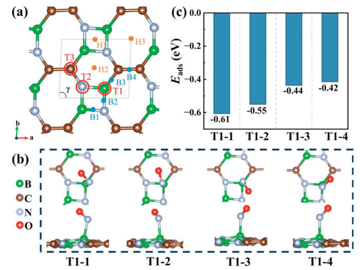
(a) Top-view of the optimized 2D BCN structure, with key adsorption sites labeled: Top (T), hollow (H), and bridge (B). (b) Four stable NO adsorption configurations. (c) Computed adsorption energies for configurations in (b).
Next, we calculated the deformation charge density and the projected density of states for the BCN monolayer, which are provided in Figs. S2 and S3 (Supporting information). These results indicate that the B atoms in the BCN monolayer exhibit electron-deficient characteristics, suggesting they may serve as the most favorable adsorption sites. To ensure a comprehensive investigation, ten possible NO adsorption configurations on the BCN monolayer were systematically evaluated (Fig. 1a). Each site was evaluated for three typical adsorption configurations: Top (T), bridge (B), and hollow (H). Finally, we identified four stable adsorption configurations in the on-top (T) geometry with different orientations on the B atom, labeled as T1–1, T1–2, T1–3, and T1–4, respectively. This finding aligns with our initial hypothesis. The corresponding adsorption energies and the optimized structures are depicted in Figs. 1b and c. Among these, T1–1 is the most stable one with an adsorption energy of −0.61 eV and was adopted for further investigation.
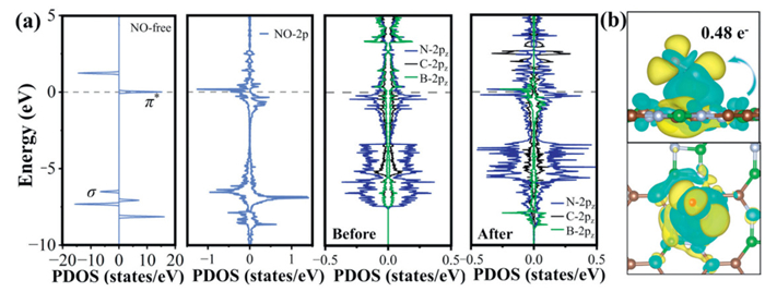
To elucidate the NO-BCN monolayer interaction mechanism, we plotted the partial density of states (PDOS) of both free NO, the bonding B atom, and its neighboring C/N atoms before and after adsorption, as shown in Fig. 2a. Obviously, a significant hybridization between the NO-2π*/σ orbital and the 2pz orbitals of the coordinated B-C-N ensemble, indicating a strong interaction between NO and the BCN surface. Charge density difference analysis (Fig. 2b) clearly demonstrates the formation of chemical bonds through an electron donation and back-donation mechanism, where electron donation from the NO lone pair to unoccupied B-2pz orbital is accompanied by back-donation from occupied C-2pz orbital and N-2pz orbital to the NO-2π* orbital. Bader charge analysis further confirms this interaction, showing a net charge transfer of 0.48 electrons from the BCN substrate to the adsorbed NO molecule. Such bidirectional charge transfer weakens the N–O bond, leading to an increased bond length of 1.21 Å (compared to 1.17 Å in free NO molecule). These results suggest that the NO molecule is effectively activated by the BCN monolayer.
Figure 2
Figure 2.
(a) Partial density of states (PDOS) of NO-2p, B-2pz, C-2pz, and N-2pz orbitals before and after NO adsorption on BCN monolayer. Here, only the directly bonded B atom and its adjacent C/N atoms are involved. (b) The charge density difference of NO adsorbed BCN (T1–1). The isosurface value is set to 0.001 e/Å3, and the accumulation and depletion charges are shown in yellow and cyan, respectively.
According to the well-established Sabatier principle in heterogeneous catalysis, the optimal catalytic activity requires intermediate adsorption strength, neither too strong to poison active sites nor too weak to enable effective activation. The BCN monolayer satisfies this balance, exhibiting moderate NO adsorption energy (−0.61 eV), showing high promising potential for NORR.
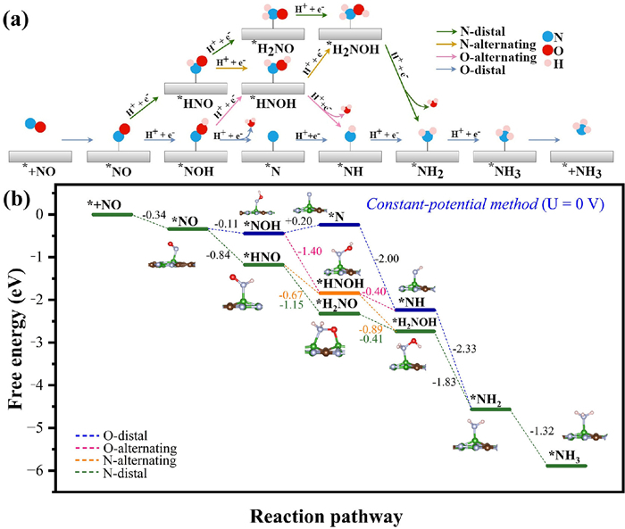
Starting from the most stable adsorption configuration (T1–1), the subsequent hydrogenation process was comprehensively investigated. Four primary reaction pathways for the conversion of NO to NH3 were considered herein: N-distal, O-distal, N-alternating, and O-alternating, as illustrated in Fig. 3a. To identify the most favorable reaction pathway, various possible intermediate configurations were optimized, and the corresponding free energy profiles were calculated (Fig. 3b).
Figure 3
Figure 3.
(a) Schematic illustration of the four possible reaction pathways of the NORR toward NH3. (b) The free energy diagram of the NORR at an applied potential of 0 V under the implicit solvation model.
In electrocatalytic systems, Fermi level alignment between the catalyst and electrode is achieved through electron transfer under the applied potential. The free energy diagram for the NORR along all considered pathways at an applied potential of 0 V versus the standard hydrogen electrode (SHE) is presented in Fig. 3b. The free energy profile reveals that all the hydrogenation steps, except for the *N formation, proceed downhill at 0 V. The energy demand for the second hydrogenation step (*NOH + H+ + e− → *N + H2O) along the O-distal pathway is only 0.2 eV, suggesting a limiting potential of −0.2 V. Conversely, the other three pathways are energetically favorable for the NO-to-NH3 conversion on the BCN monolayer at 0 V. The electrocatalytic activity of the 2D BCN monolayer is comparable to, or even superior to, that of other reported NORR electrocatalysts whose limiting potentials have been evaluated using CPM. These include NiB (0 V) [31], FeC4 (0 V) [32], 2P@C2N (0 V) [33], MN3/BP (M = V (0 V), Mo (−0.10 V), Ir (−0.06 V)) [34], boron-doped graphene (−0.35 V) [35], Si-N4 embedded graphene (−0.56 V) [30], Ge@VB (0 V) [36], Ni3/GDY (−0.05 V) [37], Cu@GDY (−0.10 V) [38], and Cr2-C2N (−0.05 V) [39]. Key performance indicators, including limiting potentials and rate-determining steps, are summarized in Table S3. This comparison highlights the competitive electrochemical activity of the 2D BCN monolayer for NORR.
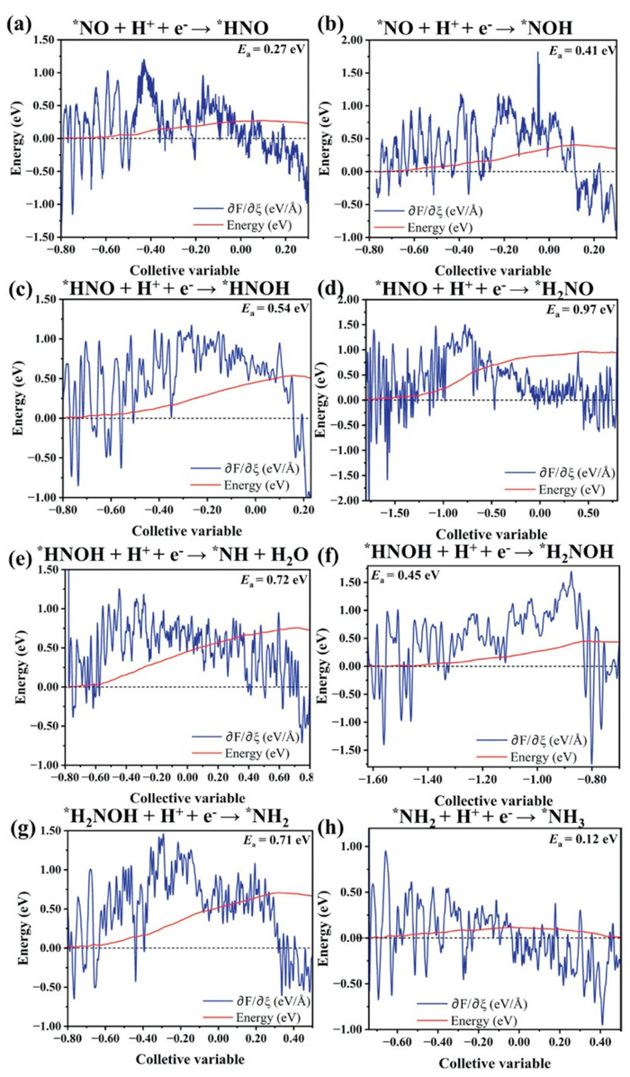
Given the critical role of kinetic barriers in governing NORR pathways, we assess hydrogenation barriers during NORR. Fig. 4 shows preferential formation of *HNO over *NOH (0.27 vs. 0.41 eV). Subsequent hydrogenation favors *HNOH (0.54 eV) over *H2NO (0.97 eV), establishing *HNOH as the dominant intermediate. The reaction then proceeds via *H2NOH (0.45 eV), bypassing the higher-barrier NH pathway (0.72 eV). When the *H2NOH generated, the further hydrogenation to produce *NH2+H2O requires overcoming an energy barrier of 0.71 eV. Finally, the hydrogenation step from *NH2 to *NH3 has the lowest barrier of 0.12 eV. Based on these results, the most favorable reaction pathway is determined as: *NO → *HNO → *HNOH → *H2NOH → *NH2 → *NH3, and the conversion of *H2NOH to *NH2 was identified as the rate-determining step (RDS) in the kinetics. All initial, transition, and final intermediate structures in the hydrogenation steps are presented in Fig. S4 (Supporting information).
Figure 4
Figure 4.
(a-h) Calculated kinetic energy barriers of different hydrogenation processes for the electrochemical reduction of NO to NH3.
Efficient catalytic cycling requires rapid product desorption to regenerate active sites. The endothermic NH3 desorption (1.13 eV, Table S1 in Supporting information) may be facilitated by thermal energy or exothermic preceding steps. Given multiple B sites on BCN biphenylene, new NO can adsorb at unoccupied B sites, enabling NO/NH3 co-adsorption. Four co-adsorption configurations (Fig. S5 in Supporting information) reveal the most stable arrangement: NO and NH3 co-adsorbed on same-side B atoms within one hexagonal ring, with an adsorption energy of −0.94 eV (Table S2 in Supporting information).
Building on this optimal configuration, NORR pathways at 0 V exhibit similar energetics (Fig. S6 in Supporting information). Under NO–NH3 co-adsorption, the N-alternating pathway emerges as thermodynamically preferred. Upon producing the second NH3, the average adsorption free energy decreases to −1.03 eV. With nine NH3 molecules saturating equivalent B-sites (same surface side), the energy further drops to −0.68 eV, a 40% reduction vs. single-NH3 adsorption (−1.13 eV), facilitating NH3 desorption and site regeneration (Fig. S7 in Supporting information). AIMD simulations (300 K, explicit water environment) confirm this regeneration: Within 5 ps, five NH3 detach from the BCN monolayer (Fig. S8 in Supporting information).
It is known that N2O and N2 are the main byproducts of the NORR, primarily formed through NO dimerization under high surface coverage. We investigated NO dimer adsorption on BCN using four representative cis- and four trans-configurations (Fig. S9 in Supporting information). Among the five identified stable dimers, as determined by their relative free energies, cis-4′ exhibits the lowest first-step hydrogenation barrier (0.18 eV, Fig. S10 in Supporting information). Subsequent reaction steps originating from this configuration (Fig. S11 in Supporting information) show thermodynamically favorable N2O formation. Notably, the *N2O2H + H+ + e− → *N2O + H2O step faces a 0.86 eV barrier, which is 0.15 eV higher than the RDS in the main NORR pathway (0.71 eV). All initial, transition, and final intermediate structures in hydrogenation steps are presented in Figs. S12 and S13 (Supporting information). Once the N2O generated, it spontaneously desorbs from the BCN monolayer due to its positive adsorption free energy. This adsorption behavior is further confirmed by AIMD simulations at 300 K (Fig. S14 in Supporting information). These kinetic constraints effectively suppress N2O/N2 formation, ensuring high NH3 selectivity.
Generally, the adsorption characteristics of key intermediates (H, NO, and NH3) exhibit dependence on electrochemical potentials, necessitating systematic evaluation across relevant electrochemical potentials. Therefore, the applied potential from −0.6 V to 0.6 V vs. SHE using a CPM is adopted for this study, as presented in Fig. S7. A negative potential shift enhances the adsorption of H and NO species, whereas NH3 adsorption exhibits an opposite potential dependence. Within the potential window of −0.4 V to 0.6 V, H* adsorption (−0.29 to 0.91 eV) remains weaker than NO/NH3. While NH3 binds more strongly than NO, this energy difference decreases with increasing NH3 coverage. For the high NH3 coverage (n = 9), the average adsorption free energy weakens from −0.68 eV (0 V) to −0.58 eV (−0.4 V), facilitating product desorption while maintaining continuous NORR cycling. Optimizing the applied potential also allows for precise control over the selectivity and catalytic efficiency of the NORR by adjusting the adsorption strengths of intermediates.
Previous research has demonstrated that the zigzag BCNRs exhibit an isolated edge state within γ = 90.0°−95.5°, arising from the annihilation of Dirac pairs in the Brillouin zone between the G and Y points [20]. This inspired us to further investigate the multifunctional roles of these edge states in NORR catalysis.
The width of nanoribbons is crucial for studying their electronic properties. For simplicity, we used the number of the zigzag atomic chain to define the nanoribbon width (N-ZBCNR), as shown in Fig. S15 (Supporting information). The width of 14 zigzag atomic chain is 30 Å, which is sufficient to investigate the edge states and electronic contribution of ZBCNRs.
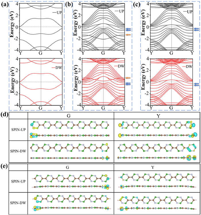
To explore the differences in the electronic properties of BCN monolayer and its nanoribbons, we first calculated their band structures, as given in Figs. 5a-c. The 2D BCN monolayer exhibits a narrow bandgap of 0.27 eV between the conduction band minimum (CBM) and valence band maximum (VBM) along the G-Y symmetry path. While for its nanoribbon along the zigzag cut (Fig. 5b), two distinct flat bands (denoted Band-Ⅰ, orange arrows) and four metallic states bridging the conduction and valence bands (denoted Band-Ⅱ, blue arrows) emerge, showing metallic character along the same path. Hydrogen saturation of edge carbon atoms leads to complete disappearance of Band-Ⅰ, confirming its origin from edge dangling bonds. The persistence of Band-Ⅱ after hydrogenation raises a question: Do these metallic states represent the theoretically predicted isolated edge states?
Figure 5
Figure 5.
The spin-up (UP) and the spin-down (DW) band structures of (a) the 2D BCN, (b) 14-ZBCNR and (c) the hydrogenated 14-ZBCNR (The orange arrow represents BAND-Ⅰ and the blue arrow represents BAND-Ⅱ). The partial charge density of the high-symmetry points G and Y within the BAND-Ⅱ at the Fermi energy surface of (d) 14-ZBCNR and (e) the hydrogenated 14-ZBCNR, respectively, with an isosurface value of 8 × 10⁻⁸ e/Å3.
To address this, we calculated partial charge density (PCHARGE) at the high-symmetry points G and Y for both ZBCNR and hydrogenated ZBCNR, as depicted in Figs. 5d and e. The electron density at the edges is significantly higher than that at the center, reinforcing the presence of edge states. To further elucidate the electron distribution of these edge states, we computed the projected band structures (PBAND) of the px, py, and pz orbitals for the edge and middle B, C, and N atoms in both systems, as shown in Figs. S16-S19 (Supporting information). The results indicate that BAND-Ⅰ originates from the px electron contribution of the edge carbon atoms, whereas BAND-Ⅱ arises from the pz electrons of the edge B, C, and N atoms, unambiguously identifying these metallic states as isolated edge states reported by previous literature [20].
Optimal nanoribbon width balances computational efficiency with NORR effectiveness. Band structure comparisons for N = {4, 6, 8, 10, 12, 14} (Fig. S20 in Supporting information) reveal convergence for N ≥ 6. Given the additional requirement for subsequent hydrogenation, N = 8 was selected as optimal for catalytic studies. Electronic structure analysis of the 8-ZBCNR system further demonstrates its characteristic edge states, as illustrated in Figs. S21-S23 (Supporting information). Furthermore, HSE06 calculations (Fig. S24 in Supporting information) verify the metallic nature of these edge states, ensuring the reliability of our findings. Additionally, we have also computed the electron mobilities of the 2D BCN (μa = 7.34 × 102 cm2 V−1 s−1, μb = 2.81 × 103 cm2 V−1 s−1) and 8-ZBCNR (μ = 3.17 × 104 cm2 V−1 s−1). The mobility increases by one to two orders of magnitude in the 8-ZBCNR, enabling rapid electron delivery to active edge sites during catalysis.
Since ZBCNRs exhibit comparable adsorption capacities for both H (−2.59 eV) and NO (−3.02 eV), it is possible that ZBCNRs with varying degrees of hydrogenation coexist in solution. To investigate this, we considered three simple and representative models: ZBCNR, the incompletely hydrogenated ZBCNR (ZBCNR-7 h), and fully hydrogenated ZBCNR (ZBCNR-8 h), as shown in the Fig. S25 (Supporting information).
We first investigated the adsorption of NO on ZBCNR-8 h. Given all the C sites are occupied by H atoms, NO can only adsorb on the perpendicular plane of the ZBCNR. Site-specific adsorption tests (Fig. S26 in Supporting information) reveal edge-state effects: Edge B sites exhibit stronger adsorption (−0.74, −0.67 eV) versus central B sites (−0.64, −0.63 eV). Subsequently, we analyzed the NORR process starting from the most stable configuration (Edge B in Fig. S26). The ZBCNR-8 h exhibits a 32% stronger NO adsorption free energy (−0.41 eV) compared to pristine 2D BCN (−0.31 eV). Furthermore, Bader charge analysis confirms enhanced charge transfer in ZBCNR-8 h, with 0.54 electrons transferred from the substrate to the adsorbate, compared to 0.48 electrons in 2D BCN. These results confirm that edge states effectively strengthen the electronic coupling between the substrate and adsorbate. The thermodynamically favored N-distal pathway (Fig. S27 in Supporting information) proceeds downhill energetically, consistent with 2D BCN behavior.
Given the similar adsorption strengths of H and NO on ZBCNR, the predominant structure in solution is likely an incompletely hydrogenated ZBCNR. Here, the simplest model, ZBCNR-7 h, is utilized to assess its NORR process. The NO adsorption free energy on ZBCNR-7 h was found to be −3.00 eV, which is considerably stronger than the NO adsorption on 2D BCN, owing to the presence of dangling bonds on the edge C atoms. The optimal reaction pathways, as depicted in the free energy diagrams (Fig. S28 in Supporting information), comprise a combination of N-alternating and N-distal paths, with all reduction processes proceeding downhill in energy. On pristine ZBCNR with unsaturated C-edges, NO adsorption strengthens further (−3.02 eV). Its NORR pathway (Fig. S29 in Supporting information) also progresses downhill energetically, combining N-alternating and N-distal mechanisms.
Clearly, both dangling bonds and isolated edge states facilitate NO capture. If vertically aligned ZBCNR arrays be artificially constructed, this tailored nanostructure would substantially enhance catalytic performance by maximizing exposure of edge-active sites. Notably, vertically oriented graphene counterparts have already been achieved through established techniques including microwave plasma-enhanced chemical vapor deposition (MPCVD) [40], plasma-enhanced chemical vapor deposition (PECVD) [41], and template-assisted growth [42]. Leveraging the structural similarity between graphene and ZBCNR, analogous methodologies could be employed to fabricate vertically aligned ZBCNR arrays, thereby amplifying their catalytic efficiency.
In summary, we systematically investigated the catalytic mechanism of electrochemical NO reduction to NH3 on BCN material. The optimal reaction pathway at 0 V proceeds via *NO → *HNO → *HNOH → *H2NOH → *NH2 → *NH3, with the hydrogenation of *H2NOH to *NH2 identified as the rate-determining step (RDS, barrier = 0.71 eV). Notably, competing N2O/N2 formation faces substantially higher kinetic barriers, exceeding the RDS barrier for NH3 production by 0.15 eV, effectively suppressing byproduct generation and ensuring high NH3 selectivity. Compared with the 2D BCN monolayer, the partially hydrogenated ZBCNR exhibits exceptional performance for NO-to-NH3 conversion due to the dangling bonds of unsaturated edge carbon atoms and the presence of edge states, leading to an optimal adsorption hierarchy-strong NO capture coupled with weak NH3 binding. Our findings reveal the BCN topological materials as highly efficient NORR electrocatalysts. Moreover, insights gained from ZBCNR's catalytic performance establish a critical framework for leveraging vertically aligned materials in NORR applications.
The authors declare that they have no known competing financial interests or personal relationships that could have appeared to influence the work reported in this paper.
Acknowledgments
This work is supported by National Natural Science Foundation of China (Nos. 22073076 and 21933009) and the Fundamental Research Funds for the Central Universities of China (No. 20720240138). Xiamen University High Performance Computing Center is acknowledged for the supercomputer resources. Shaorong Fang and Tianfu Wu from Information and Network Center of Xiamen University are acknowledged for the help with the GPU computing.
Supplementary materials
Supplementary material associated with this article can be found, in the online version, at doi:10.1016/j.cclet.2026.112768.
[1]
Q. Fan, L. Yan, M.W. Tripp, et al., Science 372 (2021) 852–856. doi: 10.1126/science.abg4509
S.B. Roy, K. Akbar, J.H. Jeon, et al., J. Mater. Chem. A 7 (2019) 20590. doi: 10.1039/c9ta07388d
[42]
S. Chaitoglou, Y. Ma, R. Ospina, et al., ACS Appl. Nano Mater. 7 (2024) 22631–22639. doi: 10.1021/acsanm.4c03320
Figure 1
(a) Top-view of the optimized 2D BCN structure, with key adsorption sites labeled: Top (T), hollow (H), and bridge (B). (b) Four stable NO adsorption configurations. (c) Computed adsorption energies for configurations in (b).
Figure 2
(a) Partial density of states (PDOS) of NO-2p, B-2pz, C-2pz, and N-2pz orbitals before and after NO adsorption on BCN monolayer. Here, only the directly bonded B atom and its adjacent C/N atoms are involved. (b) The charge density difference of NO adsorbed BCN (T1–1). The isosurface value is set to 0.001 e/Å3, and the accumulation and depletion charges are shown in yellow and cyan, respectively.
Figure 3
(a) Schematic illustration of the four possible reaction pathways of the NORR toward NH3. (b) The free energy diagram of the NORR at an applied potential of 0 V under the implicit solvation model.
Figure 5
The spin-up (UP) and the spin-down (DW) band structures of (a) the 2D BCN, (b) 14-ZBCNR and (c) the hydrogenated 14-ZBCNR (The orange arrow represents BAND-Ⅰ and the blue arrow represents BAND-Ⅱ). The partial charge density of the high-symmetry points G and Y within the BAND-Ⅱ at the Fermi energy surface of (d) 14-ZBCNR and (e) the hydrogenated 14-ZBCNR, respectively, with an isosurface value of 8 × 10⁻⁸ e/Å3.


 DownLoad:

 下载:


 下载:

