
Table 1.
Summary of reported photocatalytic reactions and corresponding activities for conventional photocatalysts and lead-free halide perovskites.

Lead-free perovskites for photocatalysis: Synthesis, mechanisms and applications
Weiqiang Zhang , Ya Chu , Baoye Hu , Longjun Xu , Guangjiu Zhao , Yan Sun , Longqing Xu , Jinsheng Zhao


With the acceleration of global industrialization, the sharp increase in energy demand has resulted in excessive dependence on fossil fuels, leading to both energy shortages and environmental pollution [1,2]. The consequent rise in CO2 emissions has exacerbated climate change, highlighting the urgent need for a transition to clean and sustainable energy sources [3–5]. Among various alternatives, solar energy is particularly attractive due to its abundance and renewability, stimulating extensive research on artificial photosynthesis. This technology offers a controllable and efficient approach to simultaneously address energy and environmental issues [6-10]. Photocatalytic systems, inspired by natural photosynthesis, enable clean solar-to-fuel conversion (e.g., hydrogen production and CO2 reduction) into hydrocarbons under ambient conditions, without secondary pollution [11]. Since the first demonstration of photocatalytic hydrogen production by TiO2 in 1972 [12], photocatalysis has evolved into a promising sustainable energy technology [13]. Although significant progress has been made in the design of photocatalysts and the understanding of their mechanisms, for instance, the use of g-C3N4 catalysts for photocatalytic production of H2O2 provides a green and environmentally friendly solution [14], the overall efficiency is still limited by rapid charge recombination and insufficient adsorption/activation of carbon dioxide [11,15]. Therefore, the development of highly efficient, stable, and environmentally friendly photocatalysts remains a key challenge.
Halide perovskites have emerged as promising photocatalysts due to their outstanding optoelectronic properties, such as strong light absorption, tunable bandgaps, high defect tolerance, and long carrier diffusion lengths [16,17]. However, their practical application is largely limited by the intrinsic toxicity of lead, which raises serious environmental and health concerns and hampers large-scale deployment [18,19]. Although various lead-free halide perovskites have been developed to address this issue, most suffer from poor stability in water and polar solvents, often requiring hydrogen halide media for operation [20]. Moreover, suboptimal bandgaps and unfavorable structural dimensionality limit charge separation, further reducing photocatalytic performance [21,22]. Therefore, the development of stable, efficient and lead-free perovskite photocatalysts remains a major challenge.
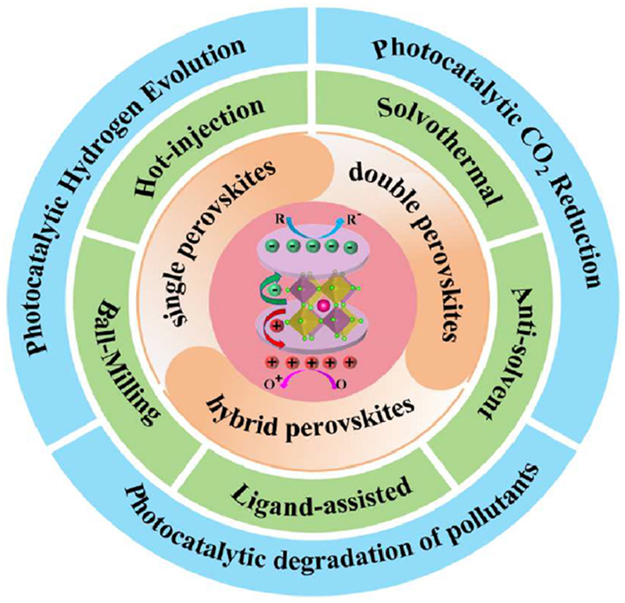
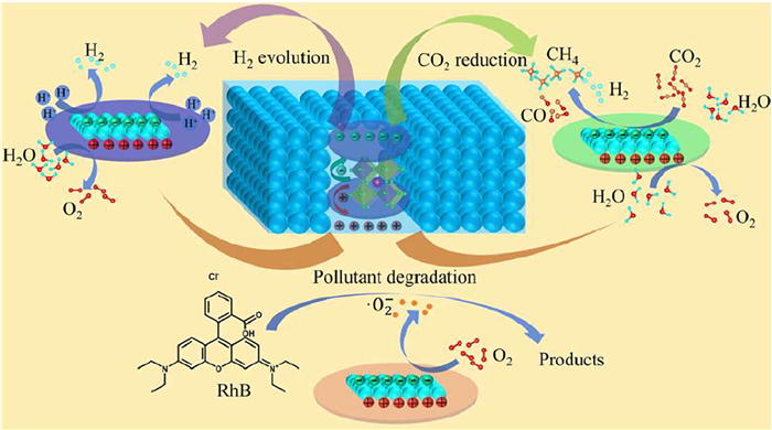
Recent years have seen extensive research on low-toxicity, stable photocatalysts with superior catalytic performance [23,24]. Lead-free halide perovskites have emerged as promising alternatives to lead-based counterparts due to their unique advantages, showing great photocatalytic potential [25]. A comparison between conventional semiconductor photocatalysts and lead-free halide perovskite systems is summarized in Table 1 [26–38]. Unlike traditional photocatalysts, lead-free halide perovskites represent an emerging class of semiconductors for light-to-chemical energy conversion, and their synthesis, photophysical behavior, and charge-transfer characteristics have been extensively investigated with advanced characterization techniques [39-41]. Although several reviews have discussed metal halide perovskites in general photocatalysis (e.g., CO2 reduction and H2 evolution), a systematic and focused overview of lead-free halide perovskites for these photocatalytic reactions remains lacking. Moreover, mechanistic challenges in CO2/H2O conversion remain poorly understood, necessitating a comprehensive analysis of progress and obstacles in this developing field. As shown in Fig. 1, this review provides a systematic overview of recent advances in lead-free halide perovskite materials for photocatalytic applications. The emphasis is placed on their synthetic approaches, crystal structure and photophysical characteristics, and additional information about their use in hydrogen evolution, CO2 minimization, and breaking down pollutants. There are also highlighted key issues and directions of future research. The purpose of this paper is to offer thorough knowledge of the photocatalysis processes of lead-free halide perovskites and give theoretical advice as well as design suggestions to create high-performance and stable lead-free photocatalysts.
 DownLoad:
CSV
| Photocatalysts | Catalytic applications (light sources) | Catalytic activity | Stability (multiple cycles) | Refs. |
| Pt-Rh/P25 | H2 evolution (300 W Xe lamp) | H2: 23, 391.0 μmol g-1 h-1 | Eight cycles (3 h per cycle) | [26] |
| Cu/ZnS | H2 evolution (λ > 400 nm, visible light, 300 W Xe lamp) | H2: 8737.9 μmol g-1 h-1 | Four cycles (5 h per cycle) | [27] |
| 9NiS/CTF-ES200 | H2 evolution (λ > 420 nm, visible light) | H2: 22.98 mmol g-1 h-1 | Four cycles (4 h per cycle) | [28] |
| WO3-x/ZnIn2S4 | H2 evolution (λ > 800 nm, 300 W Xe lamp) | H2: 14.05 μmol g-1 h-1 | Four cycles (2 h per cycle) | [29] |
| NiphenBr/PCN-1 | CO2 reduction (full-spectrum light, 300 W Xe lamp) | CO: 16.4 μmol g-1 h-1 | Four cycles (2 h per cycle) | [30] |
| Cu-CNP | CO2 reduction (full-spectrum light, 300 W Xe lamp) | CO: 923.8 μmol g-1 h-1 | Four cycles (2 h per cycle) | [31] |
| CO2-Zr12-DEPB | CO2 reduction (light intensity of 100 mW/cm2, 300 W Xe lamp) | CO: 16.72 μmol g-1 h-1 | Four cycles (2 h per cycle) | [32] |
| Cs4Co1.2Sb1.8Cl12 | CO2 reduction (λ > 420 nm, light intensity of 330 mW/cm2, 300 W Xe lamp) | CO: 130.23 μmol g-1 h-1 | five cycles (2 h per cycle) | [33] |
| Cs4MnCo0.9Bi0.1Cl12 | CO2 reduction (λ > 420 nm, light intensity of 330 mW/cm2, 300 W Xe lamp) | CO: 69.16 μmol g-1 h-1 | Four cycles (2 h per cycle) | [34] |
| Cs2AgBiBr6/CeO2 | CO2 reduction (light intensity of 100 mW/cm2, 300 W Xe lamp) | CH4: 91.9 μmol g-1 h-1 | Five cycles (5 h per cycle) | [35] |
| Pd-Cs3Sb2Cl9 | CO2 reduction (λ = 365 nm, light intensity of 2.4 W/m2, 300 W Xe lamp) | CO2 reduction photocatalytic yield: 114.9 μmol g-1 h-1 | Three cycles (2 h per cycle) | [36] |
| EDABiI5/MA3Bi2I9 | H2 evolution (λ ≥ 420 nm, light intensity of 100 mW/cm2, 300 W Xe lamp) | H2: 213.63 μmol g-1 h-1 | Ten cycles (10 h per cycle) | [37] |
| Cs3Bi2Br9/FeS2 | H2 evolution (light intensity of 100 mW/cm2, 300 W Xe lamp) | H2: 31.5 mmol g-1 h-1 | Six cycles (8 h per cycle) | [38] |
There has been a development of lead-free perovskites as eco-friendly substitutes for traditional lead-based perovskites, intending to reduce the toxicity issues related to Pb-containing compounds. From a structural standpoint, these materials usually maintain the perovskite-inspired ABX3 structure, where A is an inorganic or organic cation, and X is a non-metal anion (e.g., halides or oxides). The most important strategy is to replace Pb with other metal species that are less toxic and still have the same octahedral connectivity. Two main strategies have been followed: Partial Pb substitution by alloying, and full replacement of Pb2+ by isovalent cations like Sn2+ and Ge2+, or by heterovalent cations like Bi3+ and Sb3+, usually with some form of charge compensation scheme or production of double perovskites [42]. Therefore, the common derivative crystal structures of lead-free perovskites are A2BX6, A3B2X9 and A2BᴵBᴵᴵᴵX6. Although these compositional differences are present, the core pattern of corner-sharing octahedra is mostly preserved, with the A-site cations filling the interstitial spaces between neighboring octahedral groups [43]. Importantly, such element substitution not only preserves the structural versatility of perovskites but also significantly reduces their environmental impact, thereby providing a structural and chemical basis for the development of sustainable perovskite-based systems [44,45].
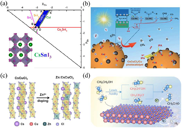
The ABX3-type lead-free halide perovskite usually consists of [BX6]4– octahedra with angle-sharing, where the B-site ions are coordinated by six X-site anions, while the A-site ions occupy the voids between adjacent octahedra [4,46]. Lead-free perovskites are usually obtained by substituting Pb with isovalent elements (Ge, Sn) or heterovalent elements (Bi, Sb) [47]. Among these, tin (Sn) has attracted considerable attention due to its similar ionic radius and comparable electronic structure. In 2014, Xu et al. revealed through first-principles calculations that the photovoltaic performance of CsSnI3 strongly depends on Sn concentration [48]. Low concentrations enhance p-type conductivity via acceptor defects, while higher concentrations reduce defects and improve solar cell efficiency (Fig. 2a). Subsequently, progress was made in copper-based perovskites, including: Zhao et al. used a simple acid-etching solution method to construct a CsCuCl3/Cu nanocrystal heterojunction (Fig. 2b), significantly increasing the selectivity of photo-catalytic CH4 to 92.7%, which was much better than that of pure CsCuCl3 (50.4%) and most lead-free perovskite catalysts [49]. Coincidentally, Lu et al. effectively regulated the electronic structure of the catalytic site by introducing Zn doping into CsCuCl3 (Fig. 2c), achieving 85.4% CH4 selectivity under visible light [50]. Meanwhile, although the CsGeX3 structure has poor stability, it shows great potential in the field of photocatalysis. For example, Li et al. first reported that the lead-free perovskite CsGeI3 can be used as an efficient photocatalyst and exhibits excellent activity in both hydrogen evolution reactions and ethanol oxidation reactions (Fig. 2d) [51]. These advancements highlight the promising potential of Sn and Ge-based lead-free perovskites as promising candidates for next-generation optoelectronic and energy conversion devices.
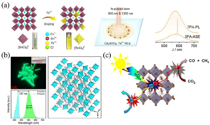
The A2BX6 family represents an important class of lead-free perovskites, typically obtained by replacing Pb2+ with tetravalent cations (e.g., Sn4+ or Te4+). Structurally, these compounds adopt a vacancy-ordered double-perovskite framework rather than the conventional ABX3 lattice. This phase can be viewed as an expanded ABX3 unit cell, in which half of the B-site cations are periodically removed, resulting in isolated [BX6]2– octahedra with no corner-sharing connectivity [52]. Such a distinct structural motif gives rise to optical and electronic behaviors markedly different from those of three-dimensional perovskites. Among lead-free candidates, Sn-based A2BX6 perovskites have attracted particular attention, and compositional engineering via ion doping has become an effective strategy to modulate their photophysical properties. For example, Zhang et al. reported Te4+-doped Cs2SnCl6 nanocrystals exhibiting broadband nonlinear optical responses, enabling multiphoton absorption from the two- to seven-photon regime (Fig. 3a) [53]. In addition, variations at the A-site can further influence emission characteristics. Su et al. developed a zero-dimensional hybrid halide (C8H14N2)2SnBr6 with narrow-band green luminescence under UV excitation (Fig. 3b), which was attributed to the low distortion of the [SnBr6]4- octahedra and the rigid organic framework [54]. Beyond photophysics, Sn-based vacancy-ordered perovskites have also been explored in photocatalysis. Rawat et al. synthesized MA2SnBr6 (MA = CH3NH2) quantum dots via a mechanochemical route (Fig. 3c), achieving notable stability in air and polar media. Under simulated or natural light irradiation, these quantum dots enabled CO2 reduction to CO/CH4 coupled with alcohol oxidation, highlighting their potential as multifunctional lead-free photocatalytic platforms [55].
The A3B2X9 family constitutes another important branch of lead-free halide perovskites, typically generated by substituting Pb2+ with trivalent cations such as Sb3+ or Bi3+. Similar to vacancy-ordered A2BX6 phases, these compounds can be regarded as derivatives of the ABX3 framework after lattice reconstruction. In A3B2X9 structures, B-site cations coordinate with halide anions to form [BX6]3– octahedra, which further assemble with A-site ions into either zero-dimensional (0D) isolated units or two-dimensional (2D) layered motifs. The dimensionality variation leads to distinct optoelectronic behaviors and reactivity profiles [56]. Compositional engineering, particularly ion doping, has proven effective in tuning the properties of A3B2X9 perovskites. For instance, Feng et al. prepared atomically dispersed Cu-doped ultrathin Cs3Bi2Br9 nanosheets via a ligand-free mechanochemical route (Fig. 4a). The addition of Cu was shown to change the electronic structure, promote charge transfer, and decrease the kinetic energy barrier to CO2 photoreduction, which caused increased CO production efficiency and stability [57]. Other than cation modulation, substitution of the anions at the X-sites is another feasible route of structural regulation. It has been reported that Cl-incorporation can cause a transformation of A3Sb2I9 into a 2D-layered structure through a phase change of a 0D-dimeric organization with a reduced bandgap and minimized radiative recombination (Fig. 4b) [58].
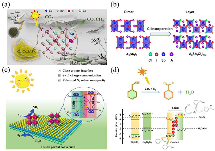
Heterojunction construction has also extended the range of photocatalysis of A3B2X9 compounds beyond the single-phase optimization. In situ partial conversion was used to fabricate an S-scheme Cs3Bi2Br9/BiOBr heterostructure based on work by Ren et al., where they successfully produced excellent interfacial charge separation photocatalytic nitrogen fixation (Fig. 4c) [59]. Likewise, Chen et al. assembled a Z-scheme Cs3Bi2Br9/Bi2WO6 composite using a reverse-solvent approach, enabling selective benzyl alcohol oxidation, where superoxide radicals were identified as the dominant reactive species (Fig. 4d) [60]. The Z-scheme charge-transfer pathway effectively preserves strong redox capability while improving carrier separation. In our recent work, we further demonstrated that targeted doping can enhance the optical response of colloidal MA3Bi2Br9 quantum dots. Specifically, In3+ incorporation significantly improved the photoluminescence efficiency while maintaining the intrinsic electronic structure of the host lattice [61].
A2BⅠBⅢX6-type double perovskites have attracted increasing attention as promising lead-free candidates, largely because they can overcome several intrinsic drawbacks of single perovskites, including limited structural stability, steric constraints, and relatively inflexible band-gap regulation [62,63]. Their characteristic framework allows the incorporation of two different cations at the B site, providing an effective handle to tailor the lattice environment and thereby modulate the electronic structure. In contrast, A-site ions mainly serve to balance charge and stabilize the [BX6] octahedral network, exerting a comparatively minor influence on the optoelectronic response [64-66]. Among these materials, Cs2AgBX6 (B = In3+, Bi3+) and Cs2NaBX6 (X = Cl–, Br–) stand out as representative systems, owing to their favorable band-gap tunability, environmentally benign composition, and competitive optoelectronic characteristics [67,68]. In 2017, Tang et al. successfully synthesized Cs2AgInCl6 single crystals with low defect density, experimentally confirming the existence of parity-forbidden transitions (Fig. 5a) [69]. Subsequently, double perovskite materials are increasingly being widely applied in the field of photocatalysis. Wang et al. synthesized a series of Cs2CuxNa1-xBiCl6 inorganic double perovskites through a simple co-precipitation method (Fig. 5b). Among them, Cs2Cu0.6Na0.4BiCl6 exhibited the optimal photocatalytic performance, which was attributed to the effective regulation of the material energy band structure by the introduction of Cu, enhancing the CO2 adsorption capacity, providing more active sites and promoting the separation of photogenerated carriers. These factors worked together to enhance the catalytic activity significantly [70]. Additionally, doping and alloying are effective strategies for further improving performance. For instance, our team has developed a series of co-doped nanocrystals Cs2NaInCl6: Bi3+: Ln3+, revealing efficient energy transfer from Bi3+ to Ln3+ and achieving highly efficient self-trapped exciton emission in these materials (Fig. 5c) [71]. At the same time, constructing heterojunctions is another important approach. For example, Huang et al. constructed the Cs2AgBiBr6/BiVO4 heterojunction, which increased the yield of CO2 reduction photocatalysis by nearly 10 times (Fig. 5d), providing a new idea for designing high-performance lead-free photocatalysts [72]. In summary, through rational structural design (such as doping, alloying, and constructing heterojunctions) to precisely control performance, the functional diversity of double perovskite materials has been significantly enhanced, and they have become candidate materials with broad application prospects in the fields of optoelectronics, catalysis and luminescence.
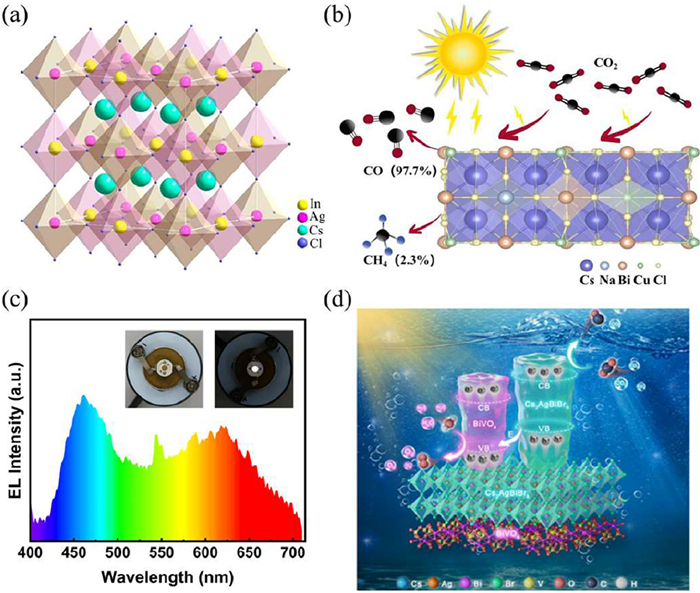
The diverse structural motifs of halide perovskites, ranging from three-dimensional ABX3 frameworks (e.g., Sn- and Ge-based) to low-dimensional or vacancy-ordered derivatives (A3B2X9, A2BX6), and double perovskites (A2BIBIIIX6), directly influence their electronic landscapes, including band dispersion, exciton binding, and defect tolerance. These structural and compositional variations not only dictate the intrinsic optoelectronic properties but also modulate their stability and interfacial interactions under operational conditions. This structural-property-stability interconnection thus provides a foundation for understanding how perovskite design governs photocatalytic performance, forming a continuous thread from materials architecture to reaction pathways, which will be discussed in the following chapters.
Developing a simple, efficient and controllable method for preparing lead-free halide perovskite photocatalysts is of great significance for their practical applications [73]. The size, morphology, dimension and defect distribution of these materials are highly sensitive to the synthesis conditions, and the structural characteristics are closely related to their photoelectric performance [22]. Therefore, various synthesis strategies have been established successively to precisely control the microstructure of perovskites to optimize their catalytic activity. The summary of the corresponding synthesis methods and catalytic performances is presented in Table 2 [74–80]. Notably, different synthetic routes often result in significant variations in the physicochemical characteristics of the resulting materials [81], which in turn directly influence catalytic activity. The process of crystal growth is especially susceptible to various factors such as the type of precursor used, concentrations of the solvent, reaction temperature and time, and organic ligand densities [82,83]. The rational choice and careful regulation of these synthesis variables are therefore important not only to obtain the required crystal structures but also to improve photocatalytic activity through alteration of active site exposure, surface defects and charge carrier dynamics. In subsequent sections, we will outline systematically some of the typical fabrication methods to make lead-free halide perovskites, such as hot-injection, solvothermal synthesis, antisolvent precipitation (ASP), and ligand-assisted reprecipitation (LARP) and explain what each method tells us about the relationships between structure, properties and performance.
DownLoad:
CSV
| Photocatalyst system | Synthetic methods | Structural characteristics | Photocatalytic reaction | Performance metric | Refs. |
| Cs2AgBiBr6/Bi2WO6 | Hot injection | Unique 0D/2D heterojunction, direct Z-scheme charge-transfer pathway confirmed by spectroscopy | CO2 reduction | CO and CH4 yield rates of 87.66 and 0.41 μmol g-1 h-1 | [74] |
| CsCu2I3/g-C3N4 | In-situ hot injection | Tight interfacial coupling with morphology evolution from 1D rods to irregular nanoparticles, possible N–I interfacial bonding | H2 evolution | H2 evolution rate of 2212 μmol g-1 h-1, AQE: 2.29% at 365 nm | [75] |
| Cs2TiX6 (X = Cl, Cl0.5Br0.5, Br) | Solvothermal | Defect-perovskite (A2BX6) framework with improved thermal/photostability and optimized band structure | CO2 reduction | CO and CH4 yield rates of 176 and 75.9 μmol g-1 h-1 | [76] |
| ((CH3)4N)3Bi2Cl9 | Solvothermal | Regulation of solvent ratio enables the transformation of phases | Pollutant degradation | 99.4% degradation efficiency of rhodamine B | [77] |
| Cs3Bi2Br9/Co-NG | Antisolvent method | Cs3Bi2Br9 as 2D nanosheets, Co single-atom anchored N-doped graphene (Co–NG) as cocatalyst | CO2 reduction | CO yield rates of 123.16 μmol g-1 h-1, near 100% CO selectivity | [78] |
| Cs2PdBr6 | Antisolvent method | The morphological transformation from micrometer crystals to nanometer crystals | CO2 reduction | CO yield rates of 73.8 μmol g-1 h-1 | [79] |
| Cs2AgSbCl6 | Ligand-assisted reprecipitation | Ligand regulates the surface ligand density and particle size (20–30 nm) | C–C coupling | The yield of the α-alkylation product is 93% | [80] |
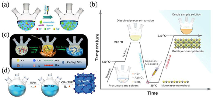
The hot-injection approach has now been established as one of the top methods of synthesizing high-quality lead-free halide perovskite nanocrystals, with precise control over the nucleation and growth processes of crystals [84]. This method involves quick injection of the precursor solutions into a preheated solvent with inert conditions, allowing almost immediate nucleation and production of highly crystalline products in less than several seconds. One of the benefits of this technique is that it allows the two steps of nucleation and growth to be clearly separated, which promotes small particle size distribution and a well-defined morphology and good colloidal stability [85]. Reaction temperature, injection rate, and precursor concentration should be strictly controlled because even minor changes can cause non-uniform particle sizes or changed surface defect densities that will influence optoelectronic properties and catalytic activity.
This hot-injection technique was initially created to synthesize quantum dots and was subsequently modified by Zhou et al. to fabricate cubic-phase Cs2AgBiBr6 double perovskite nanocrystals by using hydrobromic acid to completely ionize Ag+ species (Fig. 6a) [86]. Later investigations also revealed that hot-injection can provide a tunable morphology and performance: Liu et al. prepared two-dimensional Cs2AgBiBr6 nanosheets that have superior CO2 photoreduction efficiency (Fig. 6b) [87]; Gao et al. used an InI3-assisted approach to get Cs3Cu2I5 nanocrystals with a photoluminescence quantum yield (PLQY) of 96% and good stability (Fig. 6c) [88]; and Wu et al. surmounted the difficulty of high temperatures in producing homogeneous CsTmCl3 nanocrystals that emit efficiently in the near-UV region (Fig. 6d) [89]. These examples collectively illustrate how careful tuning of hot-injection parameters governs crystal structure, defect distribution, and surface accessibility, which are critical determinants of catalytic and optoelectronic performance. It should be noted that laboratory-scale preparation of high-quality lead-free perovskite nanocrystals remains particularly suitable for fundamental studies where precise control over crystallinity, size, and morphology is required to investigate structure-property-performance relationships systematically.
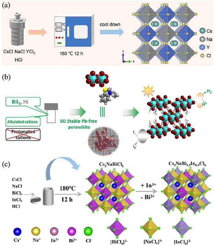
The solvothermal method is widely employed for the synthesis of lead-free halide perovskites, enabling controlled nanocrystal growth under relatively mild conditions [90]. In this approach, precursors are dissolved in a suitable solvent and sealed in an autoclave, where the reaction proceeds under elevated temperature and pressure for several hours. By adjusting parameters such as temperature, reaction time, and ligand composition, the size, morphology, and crystallinity of the resulting perovskite materials can be effectively tuned. However, this method has a long experimental period and requires high equipment costs.
Using this method, Guo et al. synthesized Sb3+/Ln3+ co-doped Cs2NaYCl6 single crystals with tunable emission properties, achieving efficient white-light photoluminescence with a photoluminescence quantum yield (PLQY) of 80.5% (Fig. 7a) [91]. The method was also applied to hybrid zero-dimensional (3-ethylbenzo[d]thiazol-3-ium)4Bi2I10 (EtbtBi2I10) perovskites and it showed its structural flexibility (Fig. 7b) [92]. Yu et al. used In3+ alloying to synthesize the Cs2NaBi0.5In0.5Cl6 crystals with increased bandgap (3.06–3.66 eV) and improved PLQY (57.63%) (Fig. 7c) [93]. The cited examples demonstrate that exact regulation of solvothermal conditions controls the growth of crystals, their dimensionality as well as distribution of defects, which directly affects their optical features, charge separation and, finally, catalytic activity. Solvothermal synthesis therefore offers a consistent pathway to design the structural stability and functional efficacy of lead-free perovskite materials.
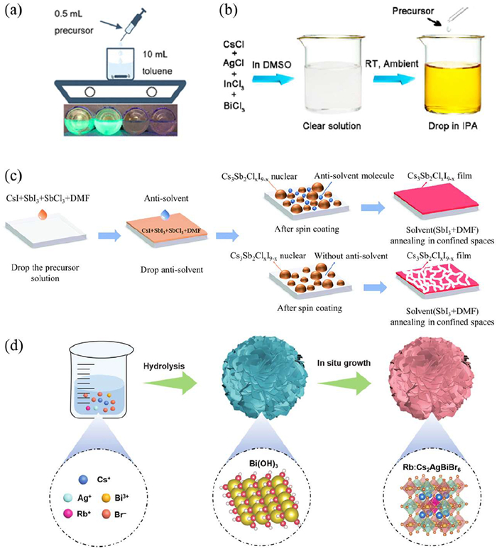
The antisolvent precipitation (ASP) method is widely adopted for the synthesis of lead-free halide perovskites due to its simplicity, low cost, and reduced environmental impact [94]. Unlike the strict thermal conditions of the hot-injection method or the rapid crystallization of ligand-assisted strategies [43], ASP allows for the rapid preparation of perovskite films or powders at room temperature. Zhang et al. successfully synthesized green-emitting Cs4SnBr6 and cyan-emitting Cs3KSnBr6 zero-dimensional perovskites via ASP, achieving PLQYs of 20% and 35%, respectively (Fig. 8a) [95]. Li et al. further optimized ASP to prepare lead-free double perovskite Cs2AgIn1-xBixCl6 nanocrystals, achieving warm white-light emission with excellent stability (Fig. 8b) [96]. Zhou et al. developed a green ASP strategy using anisole as the antisolvent, significantly improving Cs3Sb2ClxI9-x film quality (Fig. 8c) [97]. Chen et al. synthesized Rb-doped Cs2AgBiBr6 hierarchical microspheres, where Rb+ substitution modulated the electronic structure, enhanced charge separation, and introduced electron-rich Bi active sites, lowering the energy barrier for CO2 reduction (Fig. 8d) [98]. These cases demonstrate that careful control over antisolvent type, addition timing, and doping enables regulation of nucleation dynamics, morphology, and electronic structure, which in turn dictate photoluminescence and catalytic activity. ASP thus serves as a versatile strategy for balancing synthesis efficiency, structural control, and functional performance in lead-free perovskites.
The ligand-assisted reprecipitation (LARP) approach allows controlled nanocrystal growth and stabilization through the inclusion of surface ligands with which it is possible to finely tune the morphology and size without damaging the structural integrity [99]. Compared with hot-injection, LARP can be performed at room temperature and does not require an inert atmosphere or high reaction temperature. However, due to its extremely fast recrystallization rate, size control is often challenging [43]. This method is suitable for preparing highly dispersed lead-free perovskite nanocrystals and heterostructures with controlled surface properties. Wang et al. applied a modified LARP strategy to synthesize Cs2CuSbCl6 double perovskite nanocrystals under ambient conditions, replacing toxic N,N'-dimethylformamide (DMF) with methanol as the solvent. Antisolvent polarity and OA/OAm ligand ratio played key roles in determining particle size and morphology [100]. Ramolahloane et al. demonstrated that reaction temperature significantly affects the direct-to-indirect bandgap transition in Cs3Bi2Br9 nanocrystals, while optimizing oleic acid concentration tuned the bandgap from 3.85 eV to 3.29 eV with a high PLQY of 62% [101]. Recently, K+-doped perovskite QDs were prepared via LARP, showing non-monotonic PL behavior dependent on doping level [102]. These studies collectively highlight that ligand selection, solvent polarity, and reaction conditions govern nanocrystal structure, defect states, and surface chemistry, which in turn directly impact optical and catalytic properties. LARP thus provides a flexible platform for designing perovskites with tunable structure-property-performance relationships.
The main challenge in the photocatalytic application of lead-free perovskites (such as Sn- and Bi-based systems) originates from their interaction with the reaction medium, which not only governs structural stability but also directly influences the generation, migration, and utilization of photogenerated charge carriers. It is observed that various media (such as HX acids, water, and polar solvents) may induce particular degradation pathways, which result in the alteration of crystal structure integrity and the chemical conditions of active components, which are highly related to the effective charge transfer reactions during photocatalysis [103].
Although HX media (including HBr and HI) are widely used in perovskite photocatalysis, their concentration is an important factor to control material stability and interfacial charge behavior. Xu et al. controlled the supersaturation of the perovskite precursor solution by adding a suitable quantity of HBr to regulate the nucleation and growth of Cs3Bi2Br9 and enhance the film quality, which was useful to ensure the stability of charge transport and photocatalytic activity [104]. The solvent-lattice interactions can also result in structural breakdown and interfacial reconstruction when aqueous or polar solvents are present, which also leads to the influence on charge separation and surface reaction kinetics. Water has been shown to cause the Sb-based lead-free perovskite Cs3Sb2Br9 to undergo interface reconfiguration by Yuan et al. Nevertheless, the in-situ generation of a Cs3Sb2Br9/Sb4O5Br2 heterojunction is effective in inhibiting structural dissociation and promoting more stable charge transfer pathways [105]. Likewise, Wang et al. eliminated the instability of Cs2AgBiBr6 in mixed polar solvents (methanol/ethyl acetate) with a g-C3N4 coating to reduce direct solvent-lattice interaction and maintain continuous photocatalytic CO2 reduction performance during a 12 h recycling experiment [106].
The fact that Sn-based perovskites have a very strong tendency towards oxidation has a profound influence on the electronic structure and behavior of charge carriers, which is why different measures are taken to inhibit the unwanted redox processes in the reaction medium without compromising the high catalytic performance. The stability of the lead-free perovskites in photocatalysis should therefore be considered as an inseparable part of the photocatalytic mechanism, which has been triggered by the synergistic interaction between features of a reaction medium, degradation channels and control methods. Through understanding the mechanistic constraints imposed by the medium and rational design of catalyst structures and reaction conditions, it is possible to achieve both effective use of charges and extended photocatalytic efficiency.
Lead-free halide perovskite materials have a significant potential in solar-driven processes, including hydrogen evolution, CO2 reduction, degradation of pollutants, and synthesis of organic compounds, providing a promising route to the conversion of clean energy [107]. They undergo four basic stages of photocatalytic activity, which involve light absorption, charge generation and separation, carrier transport and surface redox reactions [25]. The knowledge of these processes is important to the rational development of high-performance lead-free photocatalysts. As illustrated in Fig. 9a, the general photocatalytic mechanism involves three key steps: (a) Absorption of photons (hν ≥ Eg) excites electrons from the valence band (VB) to the conduction band (CB), generating electron-hole pairs; (b) The photogenerated carriers migrate to the surface; (c) Surface-trapped electrons and holes participate in reduction and oxidation reactions, respectively. To achieve optimal photocatalytic performance, lead-free perovskites must exhibit strong and broad light absorption, efficient charge generation, and excellent chemical and structural stability [21]. As shown in Fig. 9b, the photocatalytic activity is also highly dependent on band alignment. Most lead-free halide perovskites possess suitable bandgaps and energy levels that align well with the redox potentials of key reactions, making them promising candidates for efficient solar-to-chemical energy conversion.
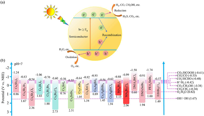
Hydrogen has attracted significant attention as a clean and sustainable fuel for large-scale energy applications [5,108], a series of lead-free perovskite-based photocatalytic materials, which were used in photocatalytic H2 evolution, are shown in Table 3 [75,92,109-120]. Among various production routes, photocatalytic water splitting is considered a highly promising strategy for solar-to-hydrogen conversion. Under light irradiation, the photocatalyst generates electron-hole pairs, which migrate to the surface and participate in redox reactions to produce hydrogen and oxygen [118]. Bandgap optimization is critical, as it governs both the light absorption range and catalytic efficiency [121]. While narrow bandgaps are favorable for visible-light harvesting, but the inherent water sensitivity of most lead-free halide perovskites limits their direct application in water splitting systems.
DownLoad:
CSV
| Photocatalyst | Reaction environment | Co-catalyst | Sacrificial reagent | Light source | Production rate (μmol g-1 h-1) | Stability (h) | Ref. |
| Cs3Bi2Br9/g-C3N4 HER (half-reaction) | H2O+TEOA | Pt | Triethanolamine (TEOA) | 1500 W Xe lamp (300 nm ≤ λ ≤ 800 nm), UV filter, 500 W/m2 | 1050 | 6 | [109] |
| DMASnBr3/g-C3N4 HER (half-reaction) | H2O+TEOA | Pt | Triethanolamine (TEOA) | 1500 W Xe lamp (300 nm≤ λ≤ 800 nm), UV filter, 500 W/m2 | 7.0 | 6 | [110] |
| PEA2SnBr4/g-C3N4 HER (half-reaction) | H2O+TEOA | Pt | Triethanolamine (TEOA) | simulated solar light, UV filter, 500 W/m2 | 1613 | 6 | [111] |
| Cs2Pt0.05Sn0.95Cl6 HER (half-reaction) | H2O+TEOA | Pt | Triethanolamine (TEOA) | Xe lamp, 300 W | 16.11 | 4 | [112] |
| MA3Bi2I9/Pt | HI | PtI2 | HI+H3PO2 | 300 W Xe lamp 400 nm cutoff filter | 169.21 | 70 | [113] |
| Cs6Cu3AgBr10 | HBr: H3PO2 = 4:1 | HBr+H3PO2 | 300 W Xe lamp | 488 | 25 | [114] | |
| EtbtBi2I10 | 4 mL H3PO2 + 16 mL HI | Pt | HI+H3PO2 | 300 W Xe lamp | 68 | 20 | [92] |
| Cs3Sb2I9/Pt | Saturated HI aqueous solution | Pt | HI | 300 W Xe lamp, Visible light source | 80.45 | 50 | [115] |
| CsCu2I3/g-C3N4 | HI: H3PO2 = 4:1 | HI+H3PO2 | 300 W Xe lamp, AM 1.5 G, 100 mW/cm2 | 2212 | 24 | [75] | |
| Cs2AgBiBr6/BP | Saturated HI-H3PO2 mixed solution | HBr+H3PO2 | 300 W Xe lamp (λ ≥ 420 nm) | 104.6 | 21 | [116] | |
| Cs2AgBiBr6/(Cu2+/Cu+) | HBr: H3PO2 = 5:1 | Cu2+/Cu+ | HBr+H3PO2 | 300 W Xe lamp (λ ≥ 420 nm), 150 mW/cm2 | 182 | 50 | [117] |
| Cs2AgBiBr6/WO3 | HBr: H3PO2 = 5:1 | HBr+H3PO2 | 300 W Xe lamp (λ ≥ 420 nm), 100 mW/cm2 | 364.89 | 12 | [118] | |
| Cs2AgBiBr6/N-C-140 | HBr: H3PO2 = 5:1 | N-C-140 | HBr+H3PO2 | 300 W Xe lamp (λ ≥ 420 nm), 100 mW/cm2 | 380 | 18 | [119] |
| Cs2AgBiBr6/NCB | Saturated HBr- H3PO2 mixed solution | NiCoB+g-C3N4 | HBr+H3PO2 | 300 W Xe lamp (λ ≥ 420 nm) | 104.6 | 15 | [120] |
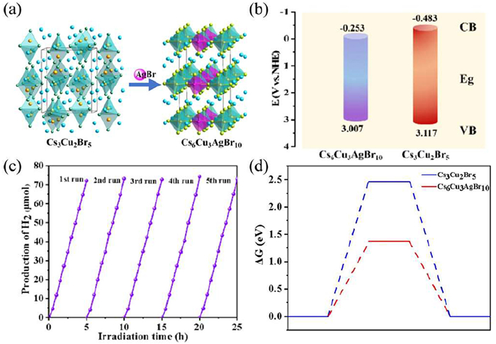
In recent years, numerous studies have utilized saturated hydrogen halide (HX) solutions to establish a precipitation–dissolution equilibrium that facilitates photocatalytic hydrogen evolution [116,119]. For example, Wang et al. synthesized a lead-free Pt-doped Cs2SnBr6 perovskite, demonstrating efficient hydrogen production in pure water [117]. Remarkably, the material maintained stable activity over one month of continuous operation (approximately 720 h). Enhanced surface hydrophobicity and the stabilization of lower-energy electronic states suppressed water-induced degradation, overcoming the typical requirement for strong acidic conditions in conventional perovskites and enabling performance under environmentally benign "green aquatic hydrogen" conditions. More recently, our group reported the controlled synthesis of highly stable all-inorganic lead-free perovskites, Cs6Cu3AgBr10 and Cs3Cu2Br5, exhibiting exceptional photocatalytic hydrogen evolution. Incorporation of Ag+ ions synergistically broadened light absorption, lowered exciton binding energy, and promoted efficient charge separation, collectively enhancing both material stability and hydrogen evolution activity (Fig. 10) [114].
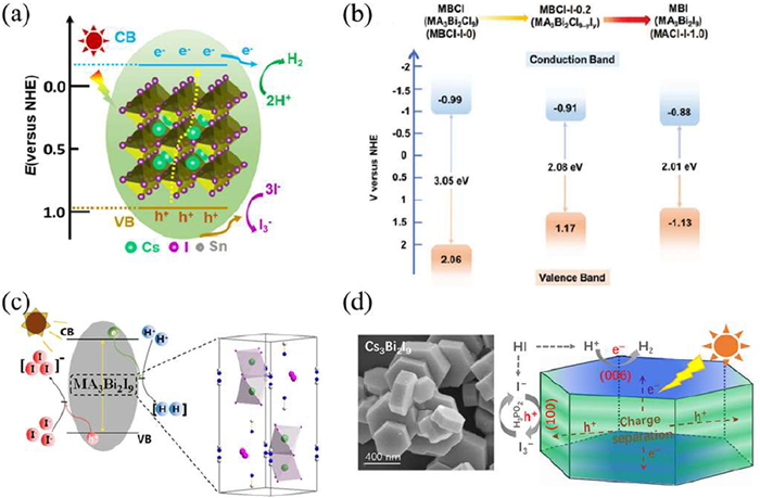
Zhou et al. designed a Cs2SnI6 graphite acid salt with enhanced environmental stability and constructed a PtSA/Cs2SnI6 catalyst by anchoring dispersed Pt-I3 species within the lattice (Fig. 11a). Pristine Cs2SnI6 suffered from severe charge recombination due to halide vacancies, exhibiting an average carrier lifetime of 109 ns. After the introduction of Pt-I3 sites, the carrier lifetime decreased to 61 ns, and steady-state photoluminescence (PL) was markedly quenched, indicating that the defect-derived Pt-I3 centers acted as efficient electron traps. This modification accelerated photogenerated electron transfer from Cs2SnI6 to Pt, suppressed non-radiative recombination, and enhanced the hydrogen evolution rate by 176.5-fold compared to conventional Cs2SnI6 loaded with Pt nanoparticles [122]. Significant progress has also been achieved with organic-inorganic hybrid perovskites. Tang et al. developed a visible-light-responsive MA3Bi2Cl9-xIx mixed-halide perovskite with excellent acid tolerance. By fine-tuning the Cl/I ratio, they constructed a bandgap funnel structure, achieving a hydrogen production rate of 341 ± 61.7 μmol/h under visible light (Fig. 11b) [123]. Similarly, Guo et al. synthesized (CH3NH2)3Bi2I9 via a hydrothermal approach (Fig. 11c), which maintained phase stability across various hydrogen iodide concentrations and resisted degradation or oxidation over 70 h of continuous photocatalysis. Upon Pt loading, the material exhibited an H2 evolution rate of 169.21 μmol g-1 h-1 [113]. All-inorganic Bi-based perovskites have also demonstrated remarkable potential. Li et al. prepared well-defined Cs3Bi2I9 hexagonal prisms using a surfactant-assisted method (Fig. 11d) [124]. The ordered arrangement of [Bi2I9]3– dimers facilitated efficient charge separation, leading to a high hydrogen evolution rate of 1504.5 μmol g-1 h-1. Collectively, these studies provide valuable guidance for designing highly active, acid-stable, lead-free perovskite photocatalysts for HX splitting. Nevertheless, the reliance on corrosive HX solutions raises environmental and safety concerns. Encouragingly, recent developments have yielded water-stable lead-free halide perovskites capable of efficient hydrogen generation under aqueous conditions.
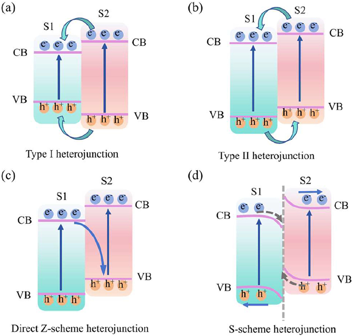
The construction of heterojunctions holds significant scientific significance and engineering value in the field of photocatalysis. Due to the inherent limitations of the band structure of single-component halide perovskites, it is often difficult to achieve an ideal balance among wide-spectrum absorption, efficient charge separation, and strong redox capabilities [125]. Heterojunctions ingeniously solve this contradiction through interface band engineering: By coupling two or more semiconductor materials with different chemical potentials, an energy band bending is induced at the interface and an intrinsically built-in electric field is formed, thereby directionally driving the separation and migration of photogenerated electrons and holes. At the same time, the heterojunction can effectively alleviate the carrier capture caused by lattice mismatch, improving the charge transport efficiency [5,126].
According to various configurations of interface energy bands, there are four main classes of heterojunction: Type I, Type II, Z-scheme and S-scheme. The mechanism of charge transfer is illustrated in Fig. 12. The key physical objectives of these four kinds of heterojunctions are all to minimize carrier recombination using accurate energy band alignment and interface control to improve photocatalytic activity. Of them, Type I structure involves embedding the whole energy band of one semiconductor into another to ensure localized charge separation; Type II structure significantly prolongs the life of the carriers by alternating between energy bands and focusing electrons and holes in different elements; Z-scheme structure typically demands the addition of metal nanoparticles or conductive bridges to act as electron mediators to facilitate selective charge recombination at the interface and thus preserve carriers with high redox potential; S-scheme heterojunction does not involve external mediators and fully relies on spatial charge separation via built-in electric fields, energy band bending and interface Coulomb effects, which are not only simpler structures but also enable minimizing the interface transmission resistance [5]. Halide perovskite-based heterojunctions have shown large potential in practice. Perovskite-based photocatalysts have been found to have increased photocatalytic activity and stability when combined with functional materials, including graphite-like carbon nitride (g-C3N4) and metal-organic frameworks (MOF), transition metal oxides and sulphides, and their photocatalytic activity in CO2 photoreduction, photocatalytic hydrogen generation, degradation of organic pollutants and nitrogen fixation reactions has been greatly improved. Consequently, heterojunction engineering has been adopted as an essential interface technique in optimizing halide perovskite photocatalytic systems. More insights on its design principles and structure-activity relationships will enhance the development of efficient and stable photocatalytic materials.
These heterojunction composites improve charge separation, facilitate interfacial electron transfer, and enhance structural stability, representing a promising strategy for efficient solar-driven hydrogen production. Carbon-based composites provide a representative example: Wang et al. developed a Cs2AgBiBr6/reduced graphene oxide (CABB/RGO) composite, which demonstrated high hydrogen evolution activity under visible light irradiation (Fig. 13a) [127]. In this system, RGO was combined with CABB via a photoreduction method, forming an M-O-C (metal-oxygen-carbon) interfacial linkage. The RGO network not only served as an efficient electron transport channel but also interacted with CABB to modulate surface defects, effectively achieving indirect defect regulation. As a result, the composite exhibited tunable photocatalytic performance while maintaining stable activity over 120 h of continuous operation.
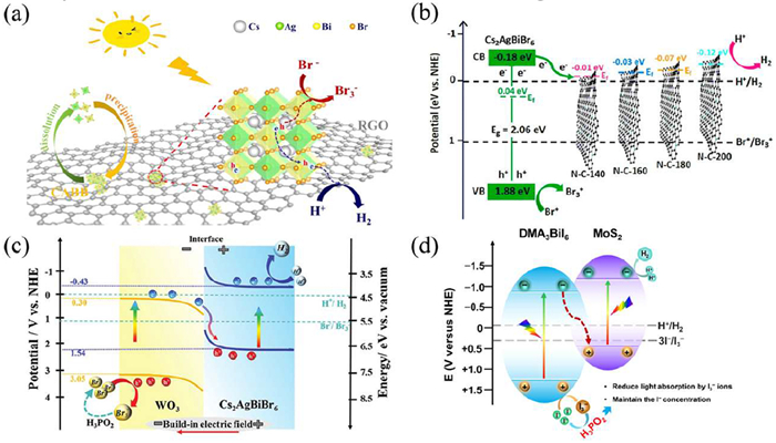
Additionally, building on this concept, nitrogen-doped carbon supports have been employed to further extend carrier lifetimes, as demonstrated by Cs2AgBiBr6/NC-140 composites, which reached a hydrogen evolution rate of 380 μmol g-1 h-1 across six catalytic cycles (Fig. 13b) [119]. Transition metal dichalcogenides offer another pathway, with MoS2/Cs2AgBiBr6 heterostructures providing efficient charge transfer and 500-hour stability under intermittent irradiation [128]. The design of S-scheme heterojunctions further optimizes directional charge migration and redox potential, exemplified by Br vacancy-enriched Cs2AgBiBr6 coupled with WO3 nanorods (VBr-Cs2AgBiBr6/WO3) (Fig. 13c) [118]. Copper-based composites, such as CsCu2I3/g-C3N4, achieve rapid electron transfer through interfacial N–I bonds via a type-II heterojunction mechanism, reaching hydrogen evolution rates as high as 2212 μmol g-1 h-1 [94]. Finally, organic–inorganic hybrids like α-MoSx/DMA3BiI6 (DMA = dimethylammonium) heterojunctions demonstrate the highest photocatalytic efficiency among bismuth-based perovskites, with hydrogen evolution of 750 μmol g-1 h-1 and an apparent quantum efficiency of 13.0% (Fig. 13d) [129]. Collectively, these studies highlight that rational heterojunction design, by integrating suitable materials and tuning interfacial properties, provides a powerful approach to maximize charge separation, generate active sites, and enhance the stability and efficiency of perovskite-based photocatalysts.
Lead-free halide perovskites have demonstrated high catalytic activity and good acid resistance; however, their limited stability in neutral aqueous environments remains a major challenge for practical applications. Recently, the hydrogen evolution reaction (HER, half-reaction) in the "aqueous phase + sacrificial agent" system has attracted significant attention. Moreover, the integration of ion doping and cocatalysts is an effective strategy for enhancing the water stability and overall performance of lead-free perovskite photocatalysts. Recent studies suggest that ion doping and cocatalyst integration are effective strategies to enhance the water stability and overall performance of lead-free perovskite photocatalysts. Ion doping has shown particular promise in improving both stability and functionality. Yin et al. developed a series of Cs2PtxSn1-xCl6 perovskites by precisely tuning the Pt4+ doping level (0 ≤ x ≤ 1), achieving materials with adjustable photoluminescence and excellent water stability (Fig. 14a) [112]. Notably, a low Pt content (x = 0.05) enabled photocatalytic hydrogen evolution, while higher doping levels (x = 0.75) enhanced PL intensity (Fig. 14b), offering valuable insight into the multifunctional design of lead-free perovskites. Cocatalyst construction and heterojunction engineering also contribute significantly to improving photocatalytic performance.
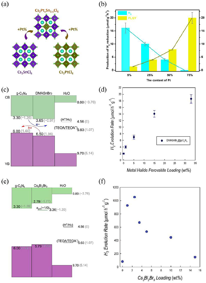
Romani et al. synthesized a PEA2SnBr4/g-C3N4 composite, which achieved a hydrogen evolution rate of 1600 μmol g-1 h-1 by promoting charge separation through favorable band alignment and suppressing electron-hole recombination [111]. Similarly, the g-C3N4/DMASnBr3 system enhanced charge transport pathways and maintained high catalytic activity while significantly improving water stability (Figs. 14c and d) [110]. In another example, a g-C3N4/Cs3Bi2Br9 heterojunction exhibited efficient charge separation due to its unique band alignment, resulting in a hydrogen evolution rate of 1050 μmol g-1 h-1 (Figs. 14e and f) [109]. These advances highlight the effectiveness of structural engineering strategies in overcoming the water instability of lead-free halide perovskites and provide a solid foundation for their practical application in photocatalytic hydrogen production.
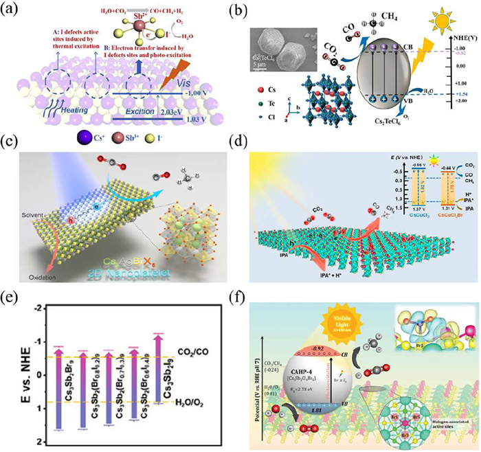
In recent years, the photocatalytic carbon dioxide (CO2) reduction technology has made significant progress. The review on lead-free perovskite photocatalytic reduction of carbon dioxide is shown in Table 4 [78,79,103,105,106,130-140]. For instance, researchers have utilized the synergy between plasma and photocatalysts to activate the reduction of carbon dioxide [141]. Compared with lead-based materials, lead-free perovskites avoid environmental and health hazards, aligning with the principles of green and sustainable development [142]. Notably, they have demonstrated considerable potential and several breakthroughs in CO2 photoreduction applications. The basic mechanism of photocatalytic CO2 reduction involves the absorption of photons when the incident light energy matches the bandgap (Eg) of the photocatalyst, generating electron-hole pairs that migrate to the surface and participate in the reduction of CO2 and oxidation of H2O [143]. Efficient photocatalysis requires that the conduction band (CB) and valence band (VB) positions are well-matched with the redox potentials of the target reactions [144]. This section summarizes recent advances in material design, performance optimization and mechanistic understanding of lead-free halide perovskites for CO2 reduction. Wang et al. developed Cs3Sb2I9 as a photocatalyst for CO/CH4 production via a photothermal-driven process, achieving a CO2 reduction rate of 95.7 μmol g-1 h-1 without sacrificial agents or cocatalysts (Fig. 15a) [145]. Tian et al. synthesized stable Cs2XCl6 (X = Hf, Zr, Te) microcrystals via solvothermal methods, achieving CO and CH4 production rates of 284.4 and 48.96 μmol/g, respectively, after 3 h of irradiation (Fig. 15b) [130]. Liu et al. prepared 2D Cs2AgBiX6 (X = Cl, Br, I) nanosheets, which exhibited significant self-trapped exciton (STE) defects. STE acts as a "temporary charge storage repository", prolonging carrier lifetime (attributed to the self-trapping emission mechanism) and preventing rapid recombination; and due to their layered structure and good charge dynamics properties, these nanosheets demonstrated efficient carbon dioxide reduction performance (Fig. 15c) [87]. In addition to structural design, ion doping strategies have been employed to enhance photocatalytic activity and stability. Zhao et al. synthesized CsCuCl3 (Eg = 1.92 eV) and Br-doped CsCuCl2Br via an antisolvent method. Br incorporation reduced the bandgap to 1.72 eV, enhanced carrier mobility, and enabled a CO2 reduction rate of 44.71 μmol g-1 h-1 (Fig. 15d) [133]. Wu et al. prepared Cs3Sb2(BrxI1-x)9 (0 ≤ x ≤ 1) nanosheets via ligand-assisted reprecipitation, tuning the bandgap from 2.1 eV to 2.5 eV. The optimized composition Cs3Sb2(Br0.7I0.3)9 showed selective CO production at 27.7 μmol g-1 h-1 (Fig. 15e) [132]. Lee et al. further demonstrated that mixed halide Cs3Sb2ClxBr9-x (0 ≤ x ≤ 9), synthesized via an antisolvent approach, exhibited enhanced charge transfer and bandgap tunability (2.59–2.90 eV), contributing to the development of lead-free perovskites for artificial redox systems (Fig. 15f) [146]. These findings highlight the great potential of lead-free halide perovskites in photocatalytic CO2 reduction and provide valuable strategies for future material optimization in artificial photosynthesis.
DownLoad:
CSV
| Photocatalyst | Reaction environment | Co-catalyst | Sacrificial reagent | Light source | Products | Production rate (μmol g-1 h-1) | Stability (h) | Ref. |
| Cs2PdBr | CO2 atmosphere | 300 W Xe lamp with 420 nm filter | CO | 24.6 | 10 | [79] | ||
| Cs2TeCl6 | CO2 gas and H2O vapor | 300 W Xe lamp | CO, CH4 | 94.8, 16.32 | 20 | [130] | ||
| Cs4Mn0.7Cu0.3Sb2Cl12 | CO2 gas and trace amounts of H2O vapor | 300 W Xe lamp | CO, CH4 | 168, 23.79 | 12 | [131] | ||
| Cs3Sb2(Br0.7I0.3)9 | CO2 atmosphere | 300 W Xe lamp with 420 nm filter, visible light | CO | 9.2 | 6 | [132] | ||
| CsCuCl2Br | EA+IPA | Isopropyl alcohol | 300 W Xe lamp, AM 1.5 G, 100 mW/cm2 | CO, CH4 | 5.61, 15.36 | 20 | [133] | |
| CsAgCl2 | CO2 gas and H2O vapor | 300 W Xe lamp | CO | 7.10 | 100 | [134] | ||
| Cs2AgBiI6 | CO2 gas and H2O vapor | 300 W Xe lamp with 420 nm filter, visible light | CO | 6.3 | 3 | [135] | ||
| Cs3Sb2Br9 | CO2 gas and H2O vapor | 300 W Xe lamp, 100 mW/cm2 | CO | 127.5 | 9 | [136] | ||
| Cs3Bi2Br9/MOF 525 Co | CO2 gas and H2O vapor | MOF 525 Co | 300 W Xe lamp, AM 1.5 G, 100 mW/cm2 | CO, CH4 | 61.2, 0.3 | 20 | [137] | |
| Cs3Bi2Br9/W18O49 | Carbon dioxide gas and toluene vapor | W18O49 | 300 W Xe lamp with 420 nm filter, 100 mW/cm2 | CO, PhCHO | 177.4, 1702.3 | 9 | [138] | |
| Cs3Bi2Br9/5Co-NG | CO2 atmosphere | Co-NG | 300 W Xe lamp, 200 mW/cm2 | CO | 123.16 | 40 | [78] | |
| Cs3Bi2Br9/In4SnS8 | CO2 atmosphere | In4SnS8 | 300 W Xe lamp with 420 nm filter | CO | 9.55 | 24 | [103] | |
| Cs3Sb2Br9/Sb4O5Br2 | CO2 atmosphere | Sb4O5Br2 | 300 W Xe lamp, 100 mW/cm2 | CO | 420 | 10 | [105] | |
| Cs3Sb2I9/NiTiO3 | CO2 atmosphere | NiTiO3 | 300 W Xe lamp | CH4 | 43.4 | 9 | [139] | |
| Cs2AgBiBr6/g-C3N4 | CO2 atmosphere, ethyl acetate and methanol | g-C3N4 | MeOH | 300 W Xe lamp, 150 mW/cm2 | CH4 | 2.0 | 12 | [106] |
| Cs2AgBiBr6-Cu-RGO | CO2 gas and H2O vapor | Cu-RGO | 300 W Xe lamp, AM 1.5 G, 100 mW/cm2 | CH4, CO, H2 | 107, 1.9, 1.0 | 12 | [140] |
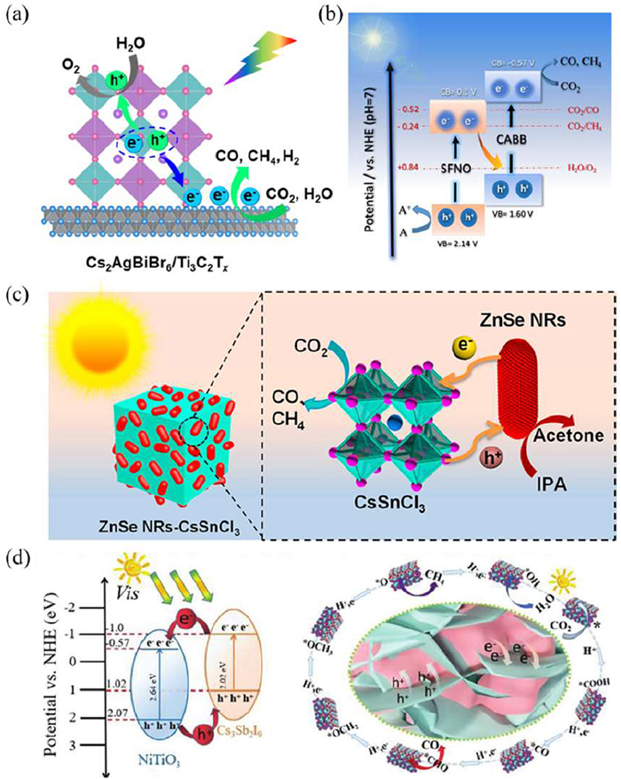
Heterojunction engineering has emerged as an effective strategy for enhancing photocatalytic CO2 reduction, primarily by promoting charge separation and suppressing carrier recombination. Various lead-free halide perovskite-based heterostructures have demonstrated promising performance in this area. Zhang et al. constructed a Cs2AgBiBr6/MXene heterostructure via electrostatic self-assembly, which significantly reduced exciton binding energy and facilitated free carrier generation (Fig. 16a) [147]. Idris et al. developed a Cs2AgBiBr6/Sr2FeNbO6 (CABB/SFNO) Z-scheme heterojunction, achieving CO and CH4 production rates of 50.00 and 8.12 μmol g-1 h-1, respectively, due to improved interfacial charge transfer (Fig. 16b) [148]. To further enhance photocatalytic stability, Kumar et al. synthesized Cs2AgBiBr6-Cu-RGO nanocomposites via mechanochemical methods. The introduction of RGO enabled efficient electron transport and surface hole migration, yielding a CH4 production rate of 93 μmol g-1 h-1 under simulated sunlight [140]. Li et al. used the electrostatic self-assembly method to combine ZnSe nanorods (NRs) with CsSnCl3, forming an II-type heterojunction. Cl-Zn or Sn-Se chemical bonds were formed between ZnSe and CsSnCl3, which not only filled some halide vacancies but also regulated the charge distribution near the defects through the built-in electric field at the interface. Moreover, this heterojunction can effectively inhibit carrier recombination and promote directional charge transfer. Compared with pure ZnSe nanorods, it significantly reduces the free energy barrier for carbon dioxide reduction (Fig. 16c) [149]. Bi-based lead-free perovskites have also shown strong potential in heterojunction systems. Zhang et al. designed an In4SnS8/Cs3Bi2Br9 heterojunction, which achieved CO production of 9.55 μmol g-1 h-1 with 92.9% selectivity, attributed to the reduced *COOH formation energy barrier [103]. Similarly, Chen et al. reported a Cs3Bi2Br9/BiOBr Z-scheme system, which exhibited CO evolution rates 4–5 times higher than the individual components [150]. Innovative synthesis approaches have further boosted heterojunction performance. Fan et al. fabricated a 3D/2D NiTiO3/Cs3Sb2I9 heterostructure via a stepwise membrane strategy (Fig. 16d), achieving a CH4 production rate of 43.4 μmol g-1 h-1 with 88.6% selectivity, outperforming most reported perovskite-based systems [139]. These advances collectively highlight the potential of heterojunction design in enhancing CO2 reduction efficiency and selectivity, offering valuable design principles for developing stable and efficient lead-free photocatalytic systems.
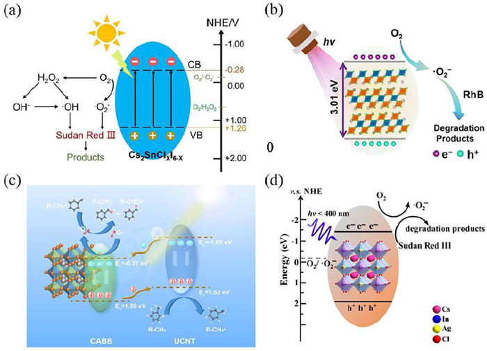
Photocatalysis has emerged as a promising green technology for the degradation of organic pollutants, offering effective solutions to pressing environmental challenges [151]. Compared with conventional treatment methods, photocatalytic processes possess distinct advantages, including low energy consumption, mild reaction conditions, and operational simplicity [105,139]. The degradation mechanism typically involves the generation of electron-hole pairs upon light irradiation, which activate molecular oxygen to produce reactive oxygen species (e.g., ·O2-), thereby promoting the mineralization of organic contaminants. Huang et al. were the first to develop lead-free double perovskite Cs2SnClxI6-x microcrystals based on the solution supersaturation recrystallization method (Fig. 17a), and applied them to the photocatalytic degradation of Sudan Red III. By adjusting the halogen composition, the optical band gap of this type of microcrystals can be continuously regulated within the range of 1.34–4.48 eV, and its photocatalytic degradation performance is significantly superior to that of many reported composite photocatalysts [152]. Qi et al. reported Cs4MnBi2Cl12 single crystals with excellent recyclability over 10 cycles, achieving 97% Rhodamine B degradation within 7 min (Fig. 17b) [153]. Notably, Song et al. developed a CABB-80@UCNT heterojunction that exhibited outstanding toluene oxidation activity (2630 μmol g-1 h-1), exceeding the performance of its components by 6–10.7 times (Fig. 17c) [154]. The catalytic superiority of double perovskites was further demonstrated by Li et al., where Cs2AgInCl6 achieved 98.5% degradation of Sudan Red III within 16 min over 5 cycles and showed efficient removal of a range of organic dyes (Fig. 17d) [155]. These findings not only expand the application scope of lead-free halide perovskite photocatalysts but also offer valuable strategies for designing highly efficient and durable systems for environmental remediation.
Photocatalytic organic transformation serves as a crucial bridge connecting basic catalytic materials with fine chemical industries and drug synthesis. The core research progress mainly focuses on important reaction pathways such as C-C bond formation and selective oxidation of alcohols [156]. For instance, Su et al. utilized a dual catalytic system constructed with polymeric carbon nitride (PCN) to achieve C-H arylation, sulfuration, and C-N cross-coupling reactions under visible light irradiation under mild conditions [157]. However, the research on such reactions in non-lead halide perovskite catalytic systems is still relatively limited. In recent years, with the continuous enhancement of the demand for "low toxicity, high efficiency, and high selectivity" catalysis in green chemistry, lead-free halide perovskites have demonstrated significant potential in photocatalytic organic transformation and are gradually becoming an important direction for expanding the frontier of photocatalytic applications. For example, Guo et al. used the environmentally friendly lead-free double perovskite Cs2AgSbCl6 nanocrystals as a model reaction, achieving C-C bond formation under visible light irradiation with high reaction yield and obtaining a high reaction selectivity of 88% for benzaldehyde [99]. Zhang et al. introduced hydrophobic alkylammonium to obtain (ODA)2CuBr4, demonstrating high activity and excellent cycling stability in the amine dehydrogenation coupling [158]. To further enhance catalytic activity and photostability, Li et al. proposed a dual modification strategy of Sn2+ doping and polyaniline (PANI) coating. The 7% Sn-doped Cs3Bi1.86Sn0.14Br8.86 sample achieved a conversion rate of 96% and a benzaldehyde selectivity of 88% in the oxidation of benzyl alcohol [159]. The research results indicate that lead-free halide perovskites have significant application potential and development prospects in the field of photocatalytic organic transformation.
Perovskite-based photocatalysts have been widely explored for applications including water splitting, CO2 reduction, and the degradation of organic pollutants. Despite the diversity of these reactions, their fundamental mechanisms share common steps: Light absorption, generation and separation of photogenerated charges, and subsequent surface redox reactions (Fig. 18). In photocatalytic water splitting, for instance, conduction band electrons drive hydrogen evolution while valence band holes participate in water oxidation, necessitating sufficient reduction/oxidation potential and efficient charge separation. To achieve this, interface engineering has proven effective: Barman et al. combined nitrogen-doped reduced graphene oxide (NrGO) with lead-free perovskite (PEA)2CoCl4 (PEA = phenylethylammonium), forming a stable electron transport channel. This not only enhanced alkali resistance but also optimized the electronic structure of Co active sites, significantly improving bifunctional electrocatalytic performance for oxygen reduction and evolution via a four-electron pathway [160]. Photocatalytic CO2 reduction presents additional challenges due to the multi-electron transfer processes involved, which demand precise band alignment, intermediate stabilization, and prolonged charge lifetimes. Heterojunction design is often employed to meet these requirements. For example, Wu et al. reported a Pd–Cs3Sb2Cl9 hetero-nanorod system in which the interface-built electric field drives photogenerated electrons from the perovskite to Pd nanoclusters. The Pd sites stabilize key intermediates such as COOH and CO via π-backdonation, lowering reaction energy barriers and enabling highly selective CO2-to-CH4 conversion [31]. In pollutant degradation, photogenerated holes and electrons primarily act through reactive oxygen species (ROS), making efficient interfacial charge transfer critical while imposing less stringent band alignment requirements. Li et al. constructed a Cs2CuBr4@ZnO S-scheme heterojunction, where the built-in electric field directs charge separation: Valence band holes on ZnO oxidize toluene to benzyl radicals, while conduction band electrons from Cs2CuBr4 activate O2 to generate ·O2-. The synergistic action of these species enables selective and efficient conversion of toluene to benzaldehyde and benzyl alcohol [161]. Overall, although different photocatalytic reactions vary in pathway complexity and product selectivity, rational modulation of band structures, interfacial charge transfer pathways, and surface microenvironments allows perovskite photocatalysts to achieve robust, high-efficiency performance within a unified photophysical-chemical framework.
To summarize, the systematic overview of the current developments in the field of lead-free halide perovskite photocatalysis is provided in this review, which includes the structural classes of these compounds, optical properties, methods of synthesis, and practical implications of these materials in hydrogen evolution, as well as CO2 reduction. This field has been studied to a lesser extent, and there are still great opportunities to explore it. Although significant advancements have been made, there are several serious challenges remaining:
(a) Photocatalytic processes of lead-free halide perovskites are not yet fully understood. In most cases, studies are based on a few successful examples obtained through prolonged trial-and-error experimentation, whereas generalization synthesis principles have not been developed. Furthermore, there is no standard purification protocol and poor comparability between studies that makes this advancement more complicated.
(b) The structural instability of lead-free halide perovskite photocatalysts in aqueous media, air, and polar solvents greatly restricts their practical use. Moreover, their catalytic activity is highly sensitive to external factors like heat and light. Though the development of heterostructures has proven to be a promising approach to enhancing the stability of the materials and facilitating the process of charge carrier transport, the knowledge of interfacial processes and the ability to withstand long term operating conditions in real-life environments are still missing.
(c) Existing lead-free halide perovskite photocatalysts have limitations due to low absorption of light and poor charge separation, which makes them perform poorly in H2 evolution and CO2 reduction. Although elemental doping is a feasible way to control the band structures, its complicated interaction with defect formation should be explored further. To look ahead, the realization of accurate defect engineering will need the ability to characterize defects accurately to identify helpful defects over damaging ones. At the same time, surface functionalization should not just be simple protection but design smart interfaces that can selectively conduct charges to target reactions. Finally, the ultimate challenge is rational design of tandem systems, requiring close energy-level matching between the combined light-harvesting elements to guarantee effective vectorial electron transfer. The combination of these approaches represents the future of shifting the material optimization of individual materials to a comprehensive, system-based photocatalytic design. Also, the combination of lead-free photocatalysts with other activation mechanisms can be a promising approach to eliminate the shortcomings of single-mode systems. In an example, it was shown recently that the combination with non-thermal plasma can be highly effective as a synergistic technique. Recent research has shown that a combination of lead-free perovskites (e.g., Cs2SnCl6) and plasma can greatly improve the CO2 conversion rate and selectivity of products by generating a reactive environment that supports photocatalysis [162,163]. Examining these photo-plasma catalytic systems might reveal new reaction pathways and increase their performance.
(d) Machine learning (ML) integration provides a revolutionary path to creating high-performance lead-free perovskite photocatalysts. Through the creation of elaborate connections between material composition, structure, and photocatalytic behavior, ML models will steer the rational creation of new systems, and it will be possible to quickly determine the candidates with the best stability, light absorption, and dynamics of charge carriers. The position of ML is set to be critical in hastening the process of creating the next generation of photocatalytic materials and processes. ML models are capable of efficiently scanning large volumes of chemical space to find viable lead-free double perovskite compositions that have the required optoelectronic properties, as evidenced in high-throughput studies [164]. In addition to the discovery of materials, ML may also be used to optimize intricate reaction conditions in multi-driver systems (e.g., photo-plasma catalysis) to achieve maximum conversion [165].
Looking forward, a multidisciplinary approach that combines novel material design, advanced characterization, and computational guidance will be essential to overcome existing bottlenecks. Future efforts should focus on elucidating reaction mechanisms, establishing universal synthesis and evaluation standards, and exploring synergistic strategies that integrate heterojunction construction, doping, defect control, and surface modification to simultaneously address stability, activity, and scalability challenges.
Weiqiang Zhang: Writing – review & editing, Resources, Conceptualization. Ya Chu: Writing – original draft, Data curation, Conceptualization. Baoye Hu: Writing – original draft, Investigation. Longjun Xu: Investigation. Guangjiu Zhao: Investigation, Formal analysis. Yan Sun: Writing – review & editing, Investigation, Formal analysis. Longqing Xu: Methodology, Investigation. Jinsheng Zhao: Writing – review & editing, Resources, Project administration.
The authors declare that they have no known competing financial interests or personal relationships that could have appeared to influence the work reported in this paper.
This work was supported by the National Natural Science Foundation of China (Nos. 22301116 and 22503042), and the Natural Science Foundations of Shandong Province (No. ZR2023QB202).
J. Qiao, Y. Liu, F. Hong, et al., Chem. Soc. Rev. 43 (2014) 631–675. doi: 10.1039/C3CS60323G
Q.Q. Song, Y.T. Zhang, J.L. Liang, et al., Chin. Chem. Lett. 35 (2024) 108797. doi: 10.1016/j.cclet.2023.108797
S. Chen, H. Yin, P. Liu, et al., Adv. Mater. 35 (2023) 2203836. doi: 10.1002/adma.202203836
J. Lee, S.P. Chai, L.L. Tan, ACS Energy Lett. 9 (2024) 1932–1975. doi: 10.1021/acsenergylett.4c00416
Y. Zhang, Z. Yu, M. Zhang, et al., J. Mater. Chem. A 12 (2024) 19757–19782. doi: 10.1039/D4TA02404D
X. Chang, T. Wang, J. Gong, Energy Environ. Sci. 9 (2016) 2177–2196. doi: 10.1039/C6EE00383D
O.S. Bushuyev, P.D. Luna, C.T. Dinh, et al., Joule 2 (2018) 825–832. doi: 10.1016/j.joule.2017.09.003
X. Li, J. Yu, M. Jaroniec, X. Chen, Chem. Rev. 119 (2019) 3962–4179. doi: 10.1021/acs.chemrev.8b00400
X. Fu, T. He, S. Zhang, et al., Chem 7 (2021) 3131–3143. doi: 10.1016/j.chempr.2021.08.009
K. Peng, J. Ye, H. Wang, et al., Appl. Catal. B: Environ. Energy 324 (2023) 122262. doi: 10.1016/j.apcatb.2022.122262
Y. Tang, C.H. Mak, G. Jia, et al., J. Mater. Chem. A 10 (2022) 12296–12316. doi: 10.1039/D2TA01170K
A. Fujishima, K. Honda, Nature 238 (1972) 37–38. doi: 10.1038/238037a0
Y. Wang, L. Luo, Z. Wang, et al., ACS Appl. Mater. Interfaces 12 (2020) 27578–27586. doi: 10.1021/acsami.0c06081
F.M. Yap, G.Z.S. Ling, B.J. Su, J.Y. Loh, W.J. Ong, Nano Res. Energy 3 (2024) 1–51.
X. Fu, T. Ren, S. Jiao, et al., J. Energy Chem. 83 (2023) 397–422. doi: 10.1016/j.jechem.2023.04.028
X. Wang, X. Sui, M. Wang, et al., Appl. Catal. B: Environ. Energy 365 (2025) 124937. doi: 10.1016/j.apcatb.2024.124937
J.R. Lv, R.T. Guo, H.W. Zhu, et al., Small 21 (2025) 2408921. doi: 10.1002/smll.202408921
S.S. Jiang, J. Zhang, J. Wang, et al., Chin. Chem. Lett. 35 (2024) 108955. doi: 10.1016/j.cclet.2023.108955
H. Zhao, R. Greco, H.P. Komsa, et al., Appl. Catal. B: Environ. Energy 357 (2024) 124318. doi: 10.1016/j.apcatb.2024.124318
J. Luo, W. Zhang, H. Yang, et al., EcoMat 3 (2021) e12079. doi: 10.1002/eom2.12079
P. Cheng, K. Han, J. Chen, ACS Mater. Lett. 5 (2022) 60–78.
Y. Feng, D. Chen, M. Niu, et al., J. Mater. Chem. A 11 (2023) 22058–22086. doi: 10.1039/D3TA04149B
N.K. Tailor, S. Singh, M.A. Afroz, et al., Appl. Catal. B: Environ. Energy 340 (2024) 123247. doi: 10.1016/j.apcatb.2023.123247
A.D. Sheikh, H.M. Yadav, K.K. Sharma, et al., Small 21 (2025) 2501570. doi: 10.1002/smll.202501570
G. Getachew, A. Wibrianto, A.S. Rasal, et al., Prog. Mater. Sci. 140 (2023) 101192. doi: 10.1016/j.pmatsci.2023.101192
W. Du, C. Zhu, W. Zhang, et al., ACS Mater. Lett. 7 (2025) 3095–3102. doi: 10.1021/acsmaterialslett.5c00894
Z. Hao, M. Hu, Z. Kang, et al., Int. J. Hydrogen Energy 106 (2025) 403–410. doi: 10.1016/j.ijhydene.2025.01.365
T. Zhou, X. Han, W. Shen, et al., Chin. Chem. Lett. 36 (2025) 110415. doi: 10.1016/j.cclet.2024.110415
Z. Chen, Y. Yan, K. Sun, et al., J. Colloid Interface Sci. 661 (2024) 12–22. doi: 10.1016/j.jcis.2024.01.150
H. Dong, C. Qu, J. Li, et al., Green Energy Environ. 11 (2026) 774–783. doi: 10.1016/j.gee.2025.09.004
J. Pang, H. Zhou, Z. Huang, et al., Chem. Eng. J. 525 (2025) 170446. doi: 10.1016/j.cej.2025.170446
B. Song, W. Song, Y. Liang, et al., Angew. Chem. Int. Ed. 64 (2025) e202421248. doi: 10.1002/anie.202421248
Y. Huang, Y. Zhou, Z. Yu, et al., Appl. Catal. B: Environ. Energy 384 (2026) 126227. doi: 10.1016/j.apcatb.2025.126227
Y. Huang, Y. Liu, Y. Liu, et al., Chem. Eng. J. 518 (2025) 164734. doi: 10.1016/j.cej.2025.164734
Y. Cai, Z. Fan, L. Wu, et al., J. Alloys Compd. 1039 (2025) 182940. doi: 10.1016/j.jallcom.2025.182940
R. Wu, X. Jia, T. Cai, et al., Adv. Funct. Mater. 36 (2026) e31006. doi: 10.1002/adfm.202531006
J. Feng, C.H. Mak, G. Jia, et al., Adv. Energy Mater. 14 (2024) 2402785. doi: 10.1002/aenm.202402785
Y. Xia, Z. He, G. He, et al., Chin. Chem. Lett. 36 (2025) 111521. doi: 10.1016/j.cclet.2025.111521
M. Shi, G. Li, W. Tian, et al., Adv. Mater. 32 (2020) 2002137. doi: 10.1002/adma.202002137
Y.X. Feng, G.X. Dong, K. Su, et al., J. Energy Chem. 69 (2022) 348–355. doi: 10.1016/j.jechem.2022.01.015
F. Cao, Y. Liu, X. Zhang, et al., Mater. Sci. Eng. R Rep. 164 (2025) 100991. doi: 10.1016/j.mser.2025.100991
M.Q. Zhang, Y.J. Zhao, G.K. Li, et al., Chin. Chem. Lett. 37 (2026) 111181. doi: 10.1016/j.cclet.2025.111181
J. Wu, J. Chen, J. Gao, et al., Energy Fuels 36 (2022) 14613–14624. doi: 10.1021/acs.energyfuels.2c03058
Y. Yang, C. Liu, M. Cai, et al., ACS Appl. Mater. Interfaces 12 (2020) 17062–17069. doi: 10.1021/acsami.0c00681
H. Lin, S. Talebi, W. MacSwain, et al., ACS Nano 19 (2025) 14941–14953. doi: 10.1021/acsnano.5c00487
C.H. Lu, G.V. Biesold-McGee, Y. Liu, Z. Kang, Z. Lin, Chem. Soc. Rev. 49 (2020) 4953–5007. doi: 10.1039/C9CS00790C
D.H. Liu, A. Wang, H.Y. Lu, et al., Chin. Chem. Lett. 35 (2024) 109285. doi: 10.1016/j.cclet.2023.109285
P. Xu, S. Chen, H.J. Xiang, et al., Chem. Mater. 26 (2014) 6068–6072. doi: 10.1021/cm503122j
H.B. Zhao, J.N. Huang, Q. Qin, et al., Small 19 (2023) 2302022. doi: 10.1002/smll.202302022
Y. Lu, A.M. Idris, P. Lu, et al., J. Catal. 447 (2025) 116104. doi: 10.1016/j.jcat.2025.116104
Y.J. Li, S.C. Tang, T. Zhao, et al., ACS Sustain. Chem. Eng. 13 (2025) 9941–9950. doi: 10.1021/acssuschemeng.5c00309
P. Bhumla, M. Jain, S. Sheoran, et al., J. Phys. Chem. Lett. 13 (2022) 11655–11662. doi: 10.1021/acs.jpclett.2c02852
W. Zhang, W. Zheng, L. Li, et al., ACS Nano 19 (2025) 18866–18873. doi: 10.1021/acsnano.5c05992
B. Su, G. Song, M.S. Molokeev, et al., Inorg. Chem. 59 (2020) 9962–9968. doi: 10.1021/acs.inorgchem.0c01103
B. Rawat, A. Kumari, M. Sachdeva, et al., EES Catal. 4 (2026) 175–188. doi: 10.1039/D5EY00169B
Z. Jin, Z. Zhang, J. Xiu, et al., J. Mater. Chem. A 8 (2020) 16166–16188. doi: 10.1039/D0TA05433J
Y. Feng, D. Chen, M. Niu, et al., Appl. Catal. B: Environ. Energy 365 (2025) 124931. doi: 10.1016/j.apcatb.2024.124931
F. Jiang, D. Yang, Y. Jiang, et al., J. Am. Chem. Soc. 140 (2018) 1019–1027. doi: 10.1021/jacs.7b10739
A.D. Ren, Z.L. Liu, S.X. Yuan, et al., J. Colloid Interface Sci. 678 (2025) 1203–1212. doi: 10.1016/j.jcis.2024.09.188
J. Chen, Y. Wu, Z. Cui, et al., Appl. Surf. Sci. 711 (2025) 164008. doi: 10.1016/j.apsusc.2025.164008
Y. Chu, Y.R. Guo, G.J. Zhao, Spectrochimi. Acta A 303 (2023) 123010. doi: 10.1016/j.saa.2023.123010
Y. Liu, A. Nag, L. Manna, Z. Xia, Angew. Chem. Int. Ed. 60 (2021) 11592–11603. doi: 10.1002/anie.202011833
J. Liu, A.A. Vedernikova, Q. Xue, et al., Adv. Sci. 12 (2025) 2416046. doi: 10.1002/advs.202416046
S. Wu, Y. Liu, Nano Res. 16 (2023) 5572–5591. doi: 10.1007/s12274-022-5232-3
Z. Wang, J. Chen, X. Xu, et al., Adv. Opt. Mater. 12 (2024) 2302617. doi: 10.1002/adom.202302617
S. Poddar, S. Mondal, S. Bhattacharjee, et al., ACS Appl. Mater. Interfaces 17 (2025) 29884–29900. doi: 10.1021/acsami.5c03940
V.K. Ravi, N. Singhal, A. Nag, J. Mater. Chem. A 6 (2018) 21666–21675. doi: 10.1039/C8TA06126B
S. Saikia, A. Joshi, H. Arfin, et al., Angew. Chem. Int. Ed. 61 (2022) e202201628. doi: 10.1002/anie.202201628
J. Luo, S. Li, H. Wu, et al., ACS Photonics 5 (2017) 398–405.
Q. Wang, X. Zhen, D. Hong, et al., J. Environ. Chem. Eng. 13 (2025) 116935. doi: 10.1016/j.jece.2025.116935
B.Y. Hu, W.Q. Zhang, G.J. Zhao, et al., Rare Metals 44 (2025) 8849–8862. doi: 10.1007/s12598-025-03475-9
W. Huang, Q. Zhu, Z. Li, Y. Zhu, J. Shen, Small 21 (2025) 2412289. doi: 10.1002/smll.202412289
Z.J. Zhang, X. Li, H.L. Tang, et al., Chin. Chem. Lett. 35 (2024) 109700. doi: 10.1016/j.cclet.2024.109700
L. Wu, S. Zheng, H. Lin, et al., J. Colloid Interface Sci. 629 (2023) 233–242. doi: 10.1016/j.jcis.2022.08.152
Y. Lv, D. Ma, C. Yang, et al., Sep. Purif. Technol. 316 (2023) 123813. doi: 10.1016/j.seppur.2023.123813
J. Zhou, D. Wu, C. Tian, et al., Small 19 (2023) 2207915. doi: 10.1002/smll.202207915
V.H. Nguyen, T. Lee, T.D. Nguyen, et al., ACS Appl. Nano Mater. 6 (2023) 3435–3445. doi: 10.1021/acsanm.2c05218
H. Fu, J. Tian, Q. Zhang, et al., Chin. J. Catal. 64 (2024) 143–151. doi: 10.1016/S1872-2067(24)60081-1
D. Wu, C. Wang, B. Huo, et al., Energy Environ. Mater. 6 (2023) e12411. doi: 10.1002/eem2.12411
Y. Guo, Y. Lou, J. Chen, et al., ChemSusChem 15 (2022) e202102334. doi: 10.1002/cssc.202102334
M. Simenas, S. Balciunas, J.N. Wilson, et al., Nat. Commun. 11 (2020) 5103. doi: 10.1038/s41467-020-18938-z
Y. Wang, J. Liu, Y. Liu, et al., J. Mater. Chem. C 12 (2024) 10267–10329. doi: 10.1039/D4TC01556H
S.A. Khan, N.Z. Khan, M. Sohail, et al., Mater. Today Phys. 34 (2023) 101079. doi: 10.1016/j.mtphys.2023.101079
K. Vighnesh, S. Wang, H. Liu, A.L. Rogach, ACS Nano 16 (2022) 19618–19625. doi: 10.1021/acsnano.2c11689
S. Ghimire, K. Oldenburg, S. Bartling, R. Lesyuk, C. Klinke, ACS Energy Lett. 7 (2022) 975–983. doi: 10.1021/acsenergylett.1c02777
L. Zhou, Y.F. Xu, B.X. Chen, D.B. Kuang, C.Y. Su, Small 14 (2018) 1703762. doi: 10.1002/smll.201703762
Z. Liu, H. Yang, J. Wang, et al., Nano Lett. 21 (2021) 1620–1627. doi: 10.1021/acs.nanolett.0c04148
F. Gao, X. Zhu, Q. Feng, et al., Nano Energy 98 (2022) 107270. doi: 10.1016/j.nanoen.2022.107270
C. Wu, X. Qing, W. Lai, X. Han, Small 19 (2023) 2300538. doi: 10.1002/smll.202300538
X. Jiang, H. Ding, F. Yang, et al., Inorg. Chem. 63 (2024) 10756–10766. doi: 10.1021/acs.inorgchem.4c01339
X.X. Guo, J.H. Wei, J.B. Luo, et al., Adv. Opt. Mater. 12 (2024) 2301914. doi: 10.1002/adom.202301914
G.N. Liu, R.Y. Zhao, B. Xu, et al., ACS Appl. Mater. Interfaces 12 (2020) 54694–54702. doi: 10.1021/acsami.0c16107
Q. Yu, S. Lv, J. Liu, et al., J. Alloys Compd. 983 (2024) 173854. doi: 10.1016/j.jallcom.2024.173854
S. Thawarkar, S.R. Rondiya, N.Y. Dzade, N. Khupse, S. Jadkar, Chem. Eur. J. 27 (2021) 7408–7417. doi: 10.1002/chem.202004902
X. Zhang, H. Wang, S. Wang, et al., Inorg. Chem. 59 (2019) 533–538.
S. Li, H. Wang, P. Yang, et al., J. Alloys Compd. 854 (2021) 156930. doi: 10.1016/j.jallcom.2020.156930
J. Zhou, F. Zhao, J. Shen, et al., J. Mater. Chem. C 9 (2021) 15301–15308. doi: 10.1039/D1TC03885K
Z. Chen, X. Jiang, H. Xu, et al., Small 20 (2024) 2401202. doi: 10.1002/smll.202401202
J. Shamsi, A.S. Urban, M. Imran, et al., Chem. Rev. 119 (2019) 3296–3348. doi: 10.1021/acs.chemrev.8b00644
S. Wang, D. Han, C. Maheu, et al., APL Mater. 11 (2023) 041110. doi: 10.1063/5.0144708
H.T. Ramolahloane, G.B. Nair, H.C. Swart, Mater. Res. Bull. 165 (2023) 112285. doi: 10.1016/j.materresbull.2023.112285
Y. Chu, C. Wang, G.J. Zhao, et al., J. Colloid Interf. Sci. 596 (2021) 199–205. doi: 10.1016/j.jcis.2021.03.128
Z. Zhang, M. Wang, Z. Chi, et al., Appl. Catal. B: Environ. Energy 313 (2022) 121426. doi: 10.1016/j.apcatb.2022.121426
J. Xu, J. Xu, S. Shi, et al., J. Alloys Compd. 968 (2023) 171886. doi: 10.1016/j.jallcom.2023.171886
S.X. Yuan, K. Su, M.R. Zhang, et al., Small 21 (2025) 2409909. doi: 10.1002/smll.202409909
Y. Wang, H. Huang, Z. Zhang, et al., Appl. Catal. B: Environ. Energy 282 (2021) 119570. doi: 10.1016/j.apcatb.2020.119570
J. Estrada-Pomares, S. Ramos-Terrón, G. Lasarte-Aragonés, et al., J. Mater. Chem. A 10 (2022) 11298–11305. doi: 10.1039/D1TA10323G
S.E. Hosseini, M.A. Wahid, Int. J. Energy Res. 44 (2020) 4110–4131. doi: 10.1002/er.4930
L. Romani, A. Speltini, C.N. Dibenedetto, et al., Adv. Funct. Mater. 31 (2021) 2104428. doi: 10.1002/adfm.202104428
L. Romani, A. Speltini, F. Ambrosio, et al., Angew. Chem. Int. Ed. 60 (2021) 3611–3618. doi: 10.1002/anie.202007584
L. Romani, A. Bala, V. Kumar, et al., J. Mater. Chem. C 8 (2020) 9189–9194. doi: 10.1039/D0TC02525A
H. Yin, J. Chen, P. Guan, et al., Angew. Chem. Int. Ed. 60 (2021) 22693–22699. doi: 10.1002/anie.202108133
Y. Guo, G. Liu, Z. Li, et al., ACS Sustain. Chem. Eng. 7 (2019) 15080–15085. doi: 10.1021/acssuschemeng.9b03761
W.Q. Zhang, Y. Chu, J.S. Zhao, et al., Sep. Purif. Technol. 357 (2025) 130111. doi: 10.1016/j.seppur.2024.130111
K. Ahmad, W. Raza, A. Alsulmi, H. Kim, Mater. Chem. Phys. 307 (2023) 128159. doi: 10.1016/j.matchemphys.2023.128159
K. Song, J. Gou, L. Wu, et al., J. Mater. Chem. C 10 (2022) 15386–15393. doi: 10.1039/D2TC03100K
T. Wang, X. Li, Z. Qin, T. Wang, Y. Zhao, J. Catal. 413 (2022) 509–516. doi: 10.1016/j.jcat.2022.07.009
H. Lv, H. Yin, N. Jiao, et al., Small Methods 7 (2023) 2201365. doi: 10.1002/smtd.202201365
Y. Jiang, K. Li, X. Wu, et al., ACS Appl. Mater. Interfaces 13 (2021) 10037–10046. doi: 10.1021/acsami.0c21588
J. Feng, Q. Long, Q. Guo, K. Song, C. Zeng, Surf. Interfaces 46 (2024) 104100. doi: 10.1016/j.surfin.2024.104100
S.A. Ali, T. Ahmad, Mater. Today Chem. 29 (2023) 101387. doi: 10.1016/j.mtchem.2023.101387
P. Zhou, H. Chen, Y. Chao, et al., Nat. Commun. 12 (2021) 4412. doi: 10.1038/s41467-021-24702-8
Y. Tang, C.H. Mak, C. Wang, et al., Small Methods 6 (2022) 2200326. doi: 10.1002/smtd.202200326
M. Li, S. Xu, L. Wu, et al., ACS Energy Lett. 7 (2022) 3370–3377. doi: 10.1021/acsenergylett.2c01856
H. Huang, D. Verhaeghe, B. Weng, et al., Angew. Chem. Int. Ed. 61 (2022) e202203261. doi: 10.1002/anie.202203261
S. Pan, J. Li, Z. Wen, et al., Adv. Energy Mater. 12 (2021) 2004002.
T. Wang, D. Yue, X. Li, et al., Appl. Catal. B: Environ. Energy 268 (2020) 118399. doi: 10.1016/j.apcatb.2019.118399
Y. Zhang, Z. Sun, Z. Wang, et al., Int. J. Hydrogen Energy 47 (2022) 8829–8840. doi: 10.1016/j.ijhydene.2021.12.255
H. Zhao, R. Greco, R. Sliz, et al., Appl. Catal. B: Environ. Energy 358 (2024) 124454. doi: 10.1016/j.apcatb.2024.124454
C. Tian, Q. Huang, D. Wu, et al., Mater. Today Energy 28 (2022) 101067. doi: 10.1016/j.mtener.2022.101067
B. Gao, C. Tian, L. Guo, et al., Adv. Sci. 11 (2024) 2307543. doi: 10.1002/advs.202307543
D. Wu, B. Huo, Y. Huang, et al., Small 18 (2022) 2106001. doi: 10.1002/smll.202106001
H.B. Zhao, J.F. Liao, Y. Teng, H.Y. Chen, D.B. Kuang, ACS Appl. Mater. Interfaces 14 (2022) 43354–43361. doi: 10.1021/acsami.2c12695
D. Wu, J. Zhou, W. Kang, et al., J. Phys. Chem. Lett. 12 (2021) 5110–5114. doi: 10.1021/acs.jpclett.1c01128
D. Wu, X. Zhao, Y. Huang, et al., Chem. Mater. 33 (2021) 4971–4976. doi: 10.1021/acs.chemmater.1c00753
C. Lu, D.S. Itanze, A.G. Aragon, et al., Nanoscale 12 (2020) 2987–2991. doi: 10.1039/C9NR07722G
N. Li, X.P. Zhai, B. Ma, et al., J. Mater. Chem. A 11 (2023) 4020–4029. doi: 10.1039/D2TA09777J
M. Zhang, X. Zhang, Z. Zhang, et al., Chem. Eng. J. 505 (2025) 159635. doi: 10.1016/j.cej.2025.159635
S. Fan, Q. Yang, G. Yin, et al., Small 20 (2024) 2311978. doi: 10.1002/smll.202311978
S. Kumar, I. Hassan, M. Regue, et al., J. Mater. Chem. A 9 (2021) 12179–12187. doi: 10.1039/D1TA01281A
L. Cao, F. Qi, N. Zhang, et al., DeCarbon 8 (2025) 100109. doi: 10.1016/j.decarb.2025.100109
F. Qi, Y. Pu, D. Wu, X. Tang, Q. Huang, Chem. Rec. 23 (2023) e202300078. doi: 10.1002/tcr.202300078
Q. Huang, C. Tian, J. Lai, et al., Inorg. Chem. 61 (2022) 14447–14454. doi: 10.1021/acs.inorgchem.2c02417
A. Kaliyaperumal, A.V. Gopala, G. Pandurangappa, et al., ACS Appl. Mater. Interfaces 17 (2025) 13896–13904. doi: 10.1021/acsami.4c20216
Y. Wang, Q. Zhou, Y. Zhu, et al., Appl. Catal. B: Environ. Energy 294 (2021) 120236. doi: 10.1016/j.apcatb.2021.120236
J. Lee, W.K. Chong, S.H.W. Kok, et al., Adv. Funct. Mater. 33 (2023) 2303430. doi: 10.1002/adfm.202303430
Z. Zhang, B. Wang, H.B. Zhao, et al., Appl. Catal. B: Environ. Energy 312 (2022) 121358. doi: 10.1016/j.apcatb.2022.121358
A.M. Idris, S. Zheng, L. Wu, et al., Chem. Eng. J. 446 (2022) 137197. doi: 10.1016/j.cej.2022.137197
N. Li, X. Chen, J. Wang, et al., ACS Nano 16 (2022) 3332–3340. doi: 10.1021/acsnano.1c11442
J. Chen, Q. Zhang, J. Song, et al., J. Catal. 442 (2025) 115874. doi: 10.1016/j.jcat.2024.115874
Q. Huang, J. Liu, F. Qi, et al., J. Environ. Chem. Eng. 11 (2023) 109960. doi: 10.1016/j.jece.2023.109960
Q. Huang, J. Zhu, J. Liu, et al., Appl. Surf. Sci. 640 (2023) 158451. doi: 10.1016/j.apsusc.2023.158451
X.F. Qi, F. Zhang, Z.P. Chen, et al., J. Mater. Chem. C 11 (2023) 3715–3725. doi: 10.1039/D3TC00185G
J. Song, C. Zhang, H. Zhang, et al., Chem. Eng. J. 453 (2023) 139748. doi: 10.1016/j.cej.2022.139748
K. Li, S. Li, W. Zhang, et al., J. Colloid Interface Sci. 596 (2021) 376–383. doi: 10.1016/j.jcis.2021.03.144
H. Wu, J. Wang, H. Sun, et al., Sci. Bull. 69 (2024) 2496–2500. doi: 10.1016/j.scib.2024.06.006
Z. Zhang, Y. Xu, Q. Zhang, et al., Sci. Bull. 67 (2022) 71–78. doi: 10.1016/j.scib.2021.08.001
S.Z. Zhang, Y.F. Gao, W.J. Li, et al., Mol. Catal. 547 (2023) 113319.
H. Li, H. Yang, B. Tian, J. Zhang, J. Mater. Chem. A 13 (2025) 34364–34374. doi: 10.1039/D5TA04958J
P. Barman, V. Kumar, K. Takeyasu, S.K. Singh, J. Mater. Chem. A 13 (2025) 16437. doi: 10.1039/D5TA02493E
M. Li, M. Li, X. Dong, G. Zhao, J. Colloid Interface Sci. 708 (2026) 139841. doi: 10.1016/j.jcis.2026.139841
Q. Huang, C.F. Fu, F. Qi, et al., J. Phys. Chem. Lett. 14 (2023) 8922–8929. doi: 10.1021/acs.jpclett.3c01696
Q. Huang, C.F. Fu, F. Qi, et al., J. Phys. Chem. C 127 (2023) 11550–11558. doi: 10.1021/acs.jpcc.3c02476
W. Luo, X.Y. Xian, Q. Huang, et al., ACS Appl. Mater. Interfaces 17 (2025) 18609–18622. doi: 10.1021/acsami.4c22272
Y.Y. Shen, Z.R. Wang, Q. Huang, et al., Green Chem. 25 (2023) 7605–7611. doi: 10.1039/D3GC02354K

Figure 2 (a) CsSnI3 crystal structure and chemical potential region. Copied with permission [48]. Copyright 2014, American Chemical Society. (b) The photocatalytic CO2 reduction reaction mechanism of CsCuCl3/Cu heterojunction. Copied with permission [49]. Copyright 2023, John Wiley and Sons. (c) Schematic diagram of the crystal structure of CsCuCl3 and Zn: CsCuCl3 [50]. Copyright 2025, Elsevier. (d) The photocatalytic mechanism of CsGeX3 [51]. Copyright 2025, American Chemical Society.

Figure 3 (a) Schematic diagram of the electronic transition of Te4+ in Cs2SnCl6: Te4+ NCs through 7PA, as well as schematic diagram of multi-photon excitation of ASE and optical properties when fs pulsed laser beam is focused on Cs2SnCl6: Te4+ NCs. Copied with permission [53]. Copyright 2025, American Chemical Society. (b) Optical photograph, optical properties, and structural diagram of (C8H14N2)2SnBr6 crystal under 365 nm ultraviolet irradiation. Copied with permission [54]. Copyright 2020, American Chemical Society. (c) Schematic diagram of the application of MA2SnBr6-type perovskite quantum dots in photocatalytic reduction of carbon dioxide and oxidation of biomass-derived compounds. Copied with permission [55]. Copyright 2025, The Royal Society of Chemistry.

Figure 4 (a) Schematic diagram of the carbon dioxide photoreduction reaction pathway of Cu-doped ultrathin Cs3Bi2Br9. Copied with permission [57]. Copyright 2025, Elsevier. (b) Schematic diagram of the phase transition from 0D two-dimensional chain-like clusters of A3Sb2I9 to two-dimensional layered A3Sb2ClXI9-X induced by the addition of chloride ions. Copied with permission [58]. Copyright 2018, American Chemical Society. (c) Crystal structure of Cs3Bi2Br9/BiOBr and the photocatalytic charge transfer mechanism. Copied with permission [59]. Copyright 2025, Elsevier. (d) Energy band positions of Cs3Bi2Br9 in Bi2WO6 and the charge transfer mechanism in contact with it. Copied with permission [60]. Copyright 2025, Elsevier.

Figure 5 (a) Crystal structure and steady state spectra of Cs2AgInCl6 SCs. Copied with permission [69]. Copyright 2017, American Chemical Society. (b) The double perovskite structure of Cs2Cu0.6Na0.4BiCl6 and its photocatalytic mechanism. Copied with permission [70]. Copyright 2025, Elsevier. (c) Electroluminescence spectra of Cs2NaInCl6: Bi3+: Ln3+. Copied with permission [71]. Copyright 2025, Nonferrous Metals Society of China. (d) The perovskite structure and photocatalytic mechanism of Cs2AgBiBr6/BiVO4 S-scheme heterojunction composite material. Copied with permission [72]. Copyright 2025, John Wiley and Sons.

Figure 6 Schematic illustration of (a) Cs2AgBiBr6 NCs. Copied with permission [86]. Copyright 2018, John Wiley and Sons. (b) Lead-free double Cs2AgBiBr6 NPLs. Copied with permission [87]. Copyright 2021, American Chemical Society. (c) Cs3Cu2I5 nanomaterials. Copied with permission [88]. Copyright 2022, Elsevier. (d) Synthesis of CsTmCl3 perovskite microcrystals. Copied with permission [89]. Copyright 2023, John Wiley and Sons.

Figure 7 (a) Schematic diagram of Cs2NaYCl6 single crystal. Copied with permission [91]. Copyright 2024, John Wiley and Sons. (b) 0D hybrid EtbtBi2I10. Copied with permission [92]. Copyright 2020, American Chemical Society. (c) Cs2NaBiCl6 and In3+ alloyed Cs2NaBi0.5In0.5Cl6 nanomaterials. Copied with permission [93]. Copyright 2024, Elsevier.

Figure 8 Schematic diagram of (a) zero-dimensional Cs4SnBr6 material. Copied with permission [95]. Copyright 2019, American Chemical Society. (b) Cs2AgIn1-xBixCl6 nanocrystals. Copied with permission [96]. Copyright 2021, Elsevier. (c) Manufacturing process flow of Cs3Sb2ClxI9-x thin film resistant to solvent regulation. Copied with permission [97]. Copyright 2021, The Royal Society of Chemistry. (d) Schematic diagram of Rb: Cs2AgBiBr6 graded microspheres. Copied with permission [98]. Copyright 2024, John Wiley and Sons.

Figure 9 (a) Schematic diagram of the photocatalytic mechanism. (b) The band structure and redox potential of lead-free halide perovskite photocatalyst.

Figure 10 (a) Synthetic route and (b) the band gap of Cs6Cu3AgBr10 and Cs3Cu2Br5. (c) Stability test of Cs6Cu3AgBr10. (d) Calculated hydrogen adsorption free energy (ΔG) of Cs6Cu3AgBr10 and Cs3Cu2Br5. Copied with permission [114]. Copyright 2024, Elsevier.

Figure 11 (a) The energy band and the charge generation and charge transfer process of Cs2SnI6. Copied with permission [122]. Copyright 2021, Springer Nature. (b) Hybrid perovskite band diagrams of MBCl, MBCl-I-0.2 and MBCl-I-1.0. Copied with permission [123]. Copyright 2022, John Wiley and Sons. (c) Hydrogen evolution and crystal structure of MA3Bi2I9 powder. Copied with permission [113]. Copyright 2019, American Chemical Society. (d) SEM image and transfer of anisotropic charges of Cs3Bi2I9 to different redox planes. Copied with permission [124]. Copyright 2022, American Chemical Society.

Figure 12 Schematic diagram of heterojunction types: (a) I-type heterojunction; (b) II-type heterojunction; (c) Direct Z-scheme heterojunction; (d) S-scheme heterojunction. CB, VB, S1 and S2 respectively represent the conduction band, the valence band, Semiconductor 1 and Semiconductor 2.

Figure 13 (a) Hydrogen evolution mechanism of Cs2AgBiBr6/RGO composite. Copied with permission [127]. Copyright 2020, Elsevier. (b) Energy band diagram of photocatalyst Cs2AgBiBr6/N-C-Th. Copied with permission [119]. Copyright 2021, American Chemical Society. (c) Charge transfer and dynamic equilibrium process of heterojunction VBr-Cs2AgBiBr6/WO3. Copied with permission [118]. Copyright 2023, John Wiley and Sons. (d) Photocatalytic mechanism of a-MoSx/DMA3BiI6 photocatalyst. Copied with permission [129]. Copyright 2024, Elsevier.

Figure 14 (a) Crystal structure and phase transformation of Cs2PtxSn1-xCl6. (b) Hydrogen evolution rates of Pt/ Cs2PtxSn1-xCl6 (0 < x < 1) with corresponding average PLQYs. Copied with permission [112]. Copyright 2021, John Wiley and Sons. (c) Band alignment of g-C3N4 and DMASnBr3 relative to water redox levels (H+/H2 and TEOA/TEOA+) at the vacuum level. (d) Hydrogen evolution rates of DMASnBr3@g-C3N4 composites with varying MHP loadings. Copied with permission [110]. Copyright 2020, John Wiley and Sons. (e) Band alignment of g-C3N4 and Cs3Bi2Br9 relative to water redox levels. (f) Hydrogen evolution rates of Cs3Bi2Br9/g-C3N4 composites with varying MHP loadings. Copied with permission [109]. Copyright 2021, John Wiley and Sons.

Figure 15 (a) The mechanism of photothermal synergistic catalyzing CO2 reduction in Cs3Sb2I9 photocatalyst. Copied with permission [145]. Copyright 2021, Elsevier. (b) Photocatalytic CO2 reduction mechanism of Cs2TeCl6. Copied with permission [130]. Copyright 2021, American Chemical Society. (c) Photocatalytic CO2 reduction mechanism of Cs2AgBiX6 nanosheets. Copied with permission [87]. Copyright 2022, American. Chemical Society. (d) Relative and photocatalytic CO2 reduction mechanism of CsCuCl3 and CsCuCl2Br. Copied with permission [133]. Copyright 2022, John Wiley and Sons. (e) Energy band arrangement of Cs3Sb2(BrxI1-x)9 (0 ≤ x ≤ 1). Copied with permission [132]. Copyright 2022, John Wiley and Sons. (f) Photocatalytic CO2 reduction mechanism proposed on Cs3Sb2Cl4Br5. Copied with permission [146]. Copyright 2023, John Wiley and Sons.

Figure 16 (a) Photocatalytic CO2 reduction mechanism of Cs2AgBiBr6/Ti3C2Tx heterostructure. Copied with permission [147]. Copyright 2022, Elsevier. (b) CO2 reduction mechanism of Cs2AgBiBr6/Sr2FeNbO6 heterojunction. Copied with permission [148]. Copyright 2022, Elsevier. (c) Assembly process and photocatalytic mechanism of ZnSe-CsSnCl3 heterojunction. Copied with permission [149]. Copyright 2022, American Chemical Society. (d) Charge transfer and CO2-to-CH4 conversion mechanism in NiTiO3/Cs3Sb2I9. Copied with permission [139]. Copyright 2024, John Wiley and Sons.

Figure 17 (a) Photocatalytic mechanism of Cs2SnClxI6-x. Copied with permission [152]. Copyright 2023, Elsevier. (b) Reaction mechanism for RhB degradation by Cs4MnBi2Cl12. Copied with permission [153]. Copyright 2023, The Royal Society of Chemistry. (c) Toluene oxidation mechanism by Cs2AgBiBr6–80@UCNT composite. Copied with permission [154]. Copyright 2021, Elsevier. (d) Photocatalytic pathway of Cs2AgInCl6 under UV irradiation. Copied with permission [155]. Copyright 2023, Elsevier.

Figure 18 Schematic diagram of lead-free halide perovskite photocatalytic applications: Photocatalytic hydrogen evolution, photocatalytic CO2 reduction, and organic matter degradation.
Table 1. Summary of reported photocatalytic reactions and corresponding activities for conventional photocatalysts and lead-free halide perovskites.
| Photocatalysts | Catalytic applications (light sources) | Catalytic activity | Stability (multiple cycles) | Refs. |
| Pt-Rh/P25 | H2 evolution (300 W Xe lamp) | H2: 23, 391.0 μmol g-1 h-1 | Eight cycles (3 h per cycle) | [26] |
| Cu/ZnS | H2 evolution (λ > 400 nm, visible light, 300 W Xe lamp) | H2: 8737.9 μmol g-1 h-1 | Four cycles (5 h per cycle) | [27] |
| 9NiS/CTF-ES200 | H2 evolution (λ > 420 nm, visible light) | H2: 22.98 mmol g-1 h-1 | Four cycles (4 h per cycle) | [28] |
| WO3-x/ZnIn2S4 | H2 evolution (λ > 800 nm, 300 W Xe lamp) | H2: 14.05 μmol g-1 h-1 | Four cycles (2 h per cycle) | [29] |
| NiphenBr/PCN-1 | CO2 reduction (full-spectrum light, 300 W Xe lamp) | CO: 16.4 μmol g-1 h-1 | Four cycles (2 h per cycle) | [30] |
| Cu-CNP | CO2 reduction (full-spectrum light, 300 W Xe lamp) | CO: 923.8 μmol g-1 h-1 | Four cycles (2 h per cycle) | [31] |
| CO2-Zr12-DEPB | CO2 reduction (light intensity of 100 mW/cm2, 300 W Xe lamp) | CO: 16.72 μmol g-1 h-1 | Four cycles (2 h per cycle) | [32] |
| Cs4Co1.2Sb1.8Cl12 | CO2 reduction (λ > 420 nm, light intensity of 330 mW/cm2, 300 W Xe lamp) | CO: 130.23 μmol g-1 h-1 | five cycles (2 h per cycle) | [33] |
| Cs4MnCo0.9Bi0.1Cl12 | CO2 reduction (λ > 420 nm, light intensity of 330 mW/cm2, 300 W Xe lamp) | CO: 69.16 μmol g-1 h-1 | Four cycles (2 h per cycle) | [34] |
| Cs2AgBiBr6/CeO2 | CO2 reduction (light intensity of 100 mW/cm2, 300 W Xe lamp) | CH4: 91.9 μmol g-1 h-1 | Five cycles (5 h per cycle) | [35] |
| Pd-Cs3Sb2Cl9 | CO2 reduction (λ = 365 nm, light intensity of 2.4 W/m2, 300 W Xe lamp) | CO2 reduction photocatalytic yield: 114.9 μmol g-1 h-1 | Three cycles (2 h per cycle) | [36] |
| EDABiI5/MA3Bi2I9 | H2 evolution (λ ≥ 420 nm, light intensity of 100 mW/cm2, 300 W Xe lamp) | H2: 213.63 μmol g-1 h-1 | Ten cycles (10 h per cycle) | [37] |
| Cs3Bi2Br9/FeS2 | H2 evolution (light intensity of 100 mW/cm2, 300 W Xe lamp) | H2: 31.5 mmol g-1 h-1 | Six cycles (8 h per cycle) | [38] |
 下载: 导出CSV
Table 2. The relationship between synthesis methods and catalytic performance.
| Photocatalyst system | Synthetic methods | Structural characteristics | Photocatalytic reaction | Performance metric | Refs. |
| Cs2AgBiBr6/Bi2WO6 | Hot injection | Unique 0D/2D heterojunction, direct Z-scheme charge-transfer pathway confirmed by spectroscopy | CO2 reduction | CO and CH4 yield rates of 87.66 and 0.41 μmol g-1 h-1 | [74] |
| CsCu2I3/g-C3N4 | In-situ hot injection | Tight interfacial coupling with morphology evolution from 1D rods to irregular nanoparticles, possible N–I interfacial bonding | H2 evolution | H2 evolution rate of 2212 μmol g-1 h-1, AQE: 2.29% at 365 nm | [75] |
| Cs2TiX6 (X = Cl, Cl0.5Br0.5, Br) | Solvothermal | Defect-perovskite (A2BX6) framework with improved thermal/photostability and optimized band structure | CO2 reduction | CO and CH4 yield rates of 176 and 75.9 μmol g-1 h-1 | [76] |
| ((CH3)4N)3Bi2Cl9 | Solvothermal | Regulation of solvent ratio enables the transformation of phases | Pollutant degradation | 99.4% degradation efficiency of rhodamine B | [77] |
| Cs3Bi2Br9/Co-NG | Antisolvent method | Cs3Bi2Br9 as 2D nanosheets, Co single-atom anchored N-doped graphene (Co–NG) as cocatalyst | CO2 reduction | CO yield rates of 123.16 μmol g-1 h-1, near 100% CO selectivity | [78] |
| Cs2PdBr6 | Antisolvent method | The morphological transformation from micrometer crystals to nanometer crystals | CO2 reduction | CO yield rates of 73.8 μmol g-1 h-1 | [79] |
| Cs2AgSbCl6 | Ligand-assisted reprecipitation | Ligand regulates the surface ligand density and particle size (20–30 nm) | C–C coupling | The yield of the α-alkylation product is 93% | [80] |
下载: 导出CSV
Table 3. Summary of hydrogen production based on lead-free perovskite photocatalysis.
| Photocatalyst | Reaction environment | Co-catalyst | Sacrificial reagent | Light source | Production rate (μmol g-1 h-1) | Stability (h) | Ref. |
| Cs3Bi2Br9/g-C3N4 HER (half-reaction) | H2O+TEOA | Pt | Triethanolamine (TEOA) | 1500 W Xe lamp (300 nm ≤ λ ≤ 800 nm), UV filter, 500 W/m2 | 1050 | 6 | [109] |
| DMASnBr3/g-C3N4 HER (half-reaction) | H2O+TEOA | Pt | Triethanolamine (TEOA) | 1500 W Xe lamp (300 nm≤ λ≤ 800 nm), UV filter, 500 W/m2 | 7.0 | 6 | [110] |
| PEA2SnBr4/g-C3N4 HER (half-reaction) | H2O+TEOA | Pt | Triethanolamine (TEOA) | simulated solar light, UV filter, 500 W/m2 | 1613 | 6 | [111] |
| Cs2Pt0.05Sn0.95Cl6 HER (half-reaction) | H2O+TEOA | Pt | Triethanolamine (TEOA) | Xe lamp, 300 W | 16.11 | 4 | [112] |
| MA3Bi2I9/Pt | HI | PtI2 | HI+H3PO2 | 300 W Xe lamp 400 nm cutoff filter | 169.21 | 70 | [113] |
| Cs6Cu3AgBr10 | HBr: H3PO2 = 4:1 | HBr+H3PO2 | 300 W Xe lamp | 488 | 25 | [114] | |
| EtbtBi2I10 | 4 mL H3PO2 + 16 mL HI | Pt | HI+H3PO2 | 300 W Xe lamp | 68 | 20 | [92] |
| Cs3Sb2I9/Pt | Saturated HI aqueous solution | Pt | HI | 300 W Xe lamp, Visible light source | 80.45 | 50 | [115] |
| CsCu2I3/g-C3N4 | HI: H3PO2 = 4:1 | HI+H3PO2 | 300 W Xe lamp, AM 1.5 G, 100 mW/cm2 | 2212 | 24 | [75] | |
| Cs2AgBiBr6/BP | Saturated HI-H3PO2 mixed solution | HBr+H3PO2 | 300 W Xe lamp (λ ≥ 420 nm) | 104.6 | 21 | [116] | |
| Cs2AgBiBr6/(Cu2+/Cu+) | HBr: H3PO2 = 5:1 | Cu2+/Cu+ | HBr+H3PO2 | 300 W Xe lamp (λ ≥ 420 nm), 150 mW/cm2 | 182 | 50 | [117] |
| Cs2AgBiBr6/WO3 | HBr: H3PO2 = 5:1 | HBr+H3PO2 | 300 W Xe lamp (λ ≥ 420 nm), 100 mW/cm2 | 364.89 | 12 | [118] | |
| Cs2AgBiBr6/N-C-140 | HBr: H3PO2 = 5:1 | N-C-140 | HBr+H3PO2 | 300 W Xe lamp (λ ≥ 420 nm), 100 mW/cm2 | 380 | 18 | [119] |
| Cs2AgBiBr6/NCB | Saturated HBr- H3PO2 mixed solution | NiCoB+g-C3N4 | HBr+H3PO2 | 300 W Xe lamp (λ ≥ 420 nm) | 104.6 | 15 | [120] |
下载: 导出CSV
Table 4. Summary of lead-free perovskite photocatalytic CO2 reduction.
| Photocatalyst | Reaction environment | Co-catalyst | Sacrificial reagent | Light source | Products | Production rate (μmol g-1 h-1) | Stability (h) | Ref. |
| Cs2PdBr | CO2 atmosphere | 300 W Xe lamp with 420 nm filter | CO | 24.6 | 10 | [79] | ||
| Cs2TeCl6 | CO2 gas and H2O vapor | 300 W Xe lamp | CO, CH4 | 94.8, 16.32 | 20 | [130] | ||
| Cs4Mn0.7Cu0.3Sb2Cl12 | CO2 gas and trace amounts of H2O vapor | 300 W Xe lamp | CO, CH4 | 168, 23.79 | 12 | [131] | ||
| Cs3Sb2(Br0.7I0.3)9 | CO2 atmosphere | 300 W Xe lamp with 420 nm filter, visible light | CO | 9.2 | 6 | [132] | ||
| CsCuCl2Br | EA+IPA | Isopropyl alcohol | 300 W Xe lamp, AM 1.5 G, 100 mW/cm2 | CO, CH4 | 5.61, 15.36 | 20 | [133] | |
| CsAgCl2 | CO2 gas and H2O vapor | 300 W Xe lamp | CO | 7.10 | 100 | [134] | ||
| Cs2AgBiI6 | CO2 gas and H2O vapor | 300 W Xe lamp with 420 nm filter, visible light | CO | 6.3 | 3 | [135] | ||
| Cs3Sb2Br9 | CO2 gas and H2O vapor | 300 W Xe lamp, 100 mW/cm2 | CO | 127.5 | 9 | [136] | ||
| Cs3Bi2Br9/MOF 525 Co | CO2 gas and H2O vapor | MOF 525 Co | 300 W Xe lamp, AM 1.5 G, 100 mW/cm2 | CO, CH4 | 61.2, 0.3 | 20 | [137] | |
| Cs3Bi2Br9/W18O49 | Carbon dioxide gas and toluene vapor | W18O49 | 300 W Xe lamp with 420 nm filter, 100 mW/cm2 | CO, PhCHO | 177.4, 1702.3 | 9 | [138] | |
| Cs3Bi2Br9/5Co-NG | CO2 atmosphere | Co-NG | 300 W Xe lamp, 200 mW/cm2 | CO | 123.16 | 40 | [78] | |
| Cs3Bi2Br9/In4SnS8 | CO2 atmosphere | In4SnS8 | 300 W Xe lamp with 420 nm filter | CO | 9.55 | 24 | [103] | |
| Cs3Sb2Br9/Sb4O5Br2 | CO2 atmosphere | Sb4O5Br2 | 300 W Xe lamp, 100 mW/cm2 | CO | 420 | 10 | [105] | |
| Cs3Sb2I9/NiTiO3 | CO2 atmosphere | NiTiO3 | 300 W Xe lamp | CH4 | 43.4 | 9 | [139] | |
| Cs2AgBiBr6/g-C3N4 | CO2 atmosphere, ethyl acetate and methanol | g-C3N4 | MeOH | 300 W Xe lamp, 150 mW/cm2 | CH4 | 2.0 | 12 | [106] |
| Cs2AgBiBr6-Cu-RGO | CO2 gas and H2O vapor | Cu-RGO | 300 W Xe lamp, AM 1.5 G, 100 mW/cm2 | CH4, CO, H2 | 107, 1.9, 1.0 | 12 | [140] |
下载: 导出CSV

 扫一扫看文章


扫一扫关注我们

 下载: