Citation:
Gang Zhao, Yuxin Dai, Ning Zhao, Lan Mu, Mei Xue, Chenan Xu, Tianyong Zhang. Design strategies and performance optimization of nickel-based bifunctional electrocatalysts for green hydrogen via overall water splitting[J]. Chinese Chemical Letters,
2026, 37(10): 112691.
doi:
10.1016/j.cclet.2026.112691
Design strategies and performance optimization of nickel-based bifunctional electrocatalysts for green hydrogen via overall water splitting
English
Design strategies and performance optimization of nickel-based bifunctional electrocatalysts for green hydrogen via overall water splitting
tyzhang@tju.edu.cn (T. Zhang). 1 These authors contributed equally to this work.
Received Date:
06 January 2026 Accepted Date:
26 March 2026 Revised Date:
12 March 2026 Available Online:
15 October 2026
Abstract:
Hydrogen energy is a key clean and sustainable alternative to fossil fuels. Producing “green hydrogen” via water electrolysis using renewable energy is a leading approach, but high costs and reliance on scarce precious metal catalysts like platinum and iridium remain major barriers. Developing affordable, efficient, and stable non-precious metal catalysts is therefore essential for scaling up green hydrogen technology. Nickel-based materials have emerged as promising candidates due to their good electrocatalytic activity for both hydrogen and oxygen evolution reactions, corrosion resistance, and low cost. Recent studies have focused on nickel-based compounds such as hydroxides, sulfides, selenides, and phosphates as bifunctional catalysts. However, their performance still lags precious metals in activity and stability, necessitating further improvement through material modification. This review examines the fundamental mechanisms of electrocatalysis and explores strategies to enhance nickel-based catalysts, including anion/cation doping, microstructure control, and heterointerface engineering. These approaches help optimize electronic structures, increase surface area, and improve mass transfer, thereby boosting catalytic activity and durability. Finally, the practical potential and development pathway of high-performance nickel-based electrocatalysts for large-scale green hydrogen production are discussed.
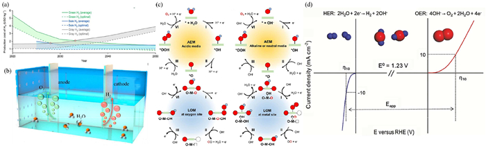
The large-scale mining and combustion of fossil fuels have led to a sharp increase in greenhouse gas emissions, exacerbating global climate change and posing a serious threat to ecological balance [1]. With the acceleration of the global energy structure transformation process, hydrogen energy, as a clean, efficient and sustainable energy carrier, is regarded as an important alternative to fossil fuels [2,3]. It is expected that by 2050, the proportion of hydrogen energy in China’s energy consumption structure will increase to 10%, which is expected to drive fundamental changes in the energy system and lead the third energy revolution [4,5]. At present, “grey hydrogen” produced based on fossil fuels still dominates in the medium and short term. However, considering the policy orientation and the potential for cost reduction (Fig. 1a), the sustainable development path of hydrogen energy in the future will rely more on “green hydrogen” produced by electrolyzing water [6]. The electrolysis of water using renewable energy to produce “green hydrogen” has become a major trend. Building an infrastructure system that takes hydrogen energy as the energy carrier and integrates renewable clean energy with seasonal, fluctuating and unevenly distributed characteristics is conducive to achieving efficient development and utilization of clean energy. At present, the technology of hydrogen production through water electrolysis has become relatively mature, capable of converting unstable renewable energy sources such as wind and solar power into stable hydrogen energy, demonstrating excellent system adaptability and integration capabilities [7]. Hydrogen production through electrolysis of water using new energy power generation is not only an effective means to promote the consumption of fluctuating new energy sources such as wind power and photovoltaic power, but also an important development direction for promoting the deep decarbonization of the power system.
Figure 1
Figure 1.
(a) Production costs for grey hydrogen, blue hydrogen and green hydrogen from 2020 to 2050, where the solid lines are the average costs, and the dashed lines are the optimal costs. Copied with permission [6]. Copyright 2023, Royal Society of Chemistry. (b) Hydrogen evolution reaction (HER) and oxygen evolution reaction (OER) of electrocatalytic water splitting. Reproduced with permission [21]. Copyright 2021, Elsevier B.V. (c) Schematic illustration of AEM pathways for the OER under acidic and alkaline/neutral conditions. Schematic illustration of LOM pathways for OER on oxygen site and metal site. Reproduced with permission [29]. Copyright 2013, Royal Society of Chemistry. (d) The typical HER and OER polarization curves. η10 represents the overpotential that required to achieve a current density of 10 mA/cm2. Reproduced with permission [31]. Copyright 2021, Wiley-VCH GmbH.
Hydrogen production through water electrolysis is essentially an electrochemical reaction involving complex interface processes, and its efficiency is limited by the kinetics of electron transfer and material transport between the solid and liquid phases. This process consists of two semi-reactions: Hydrogen evolution reaction (HER) occurs at the cathode, and oxygen evolution reaction (OER) takes place at the anode [8]. Among them, HER is a two-electron transfer process with relatively fast dynamics; OER involves four-electron transfer, with a complex reaction path and slow kinetics. Therefore, it is often regarded as the rate-controlling step of the entire water splitting process. To lower the reaction energy barrier of OER, highly efficient electrocatalysts are usually required. At present, noble metal-based catalysts (such as Pt, Pd, IrO2 and RuO2) have been widely studied due to their high catalytic activity and good corrosion resistance. For instance, commercialized Pt/C catalysts are regarded as the benchmark material for HER. Their advantage stems from the fact that metallic Pt has a nearly ideal adsorption Gibbs free energy for hydrogen intermediates (H*), following Sabatier's principle, which makes the adsorption/desorption process of hydrogen on its surface easy to proceed [9,10]; IrO2 and RuO2 are the benchmark catalysts for OER. However, the scarcity and high cost of precious metal resources have severely restricted their application in large-scale industrial electrolytic water hydrogen production [11]. Therefore, developing resource-rich and low-cost non-precious metal transition metal-based bifunctional electrocatalysts to achieve efficient and stable total water splitting has become an important research direction at present [12]. Researchers are committed to designing bifunctional catalysts that exhibit high activity and stability in both HER and OER through strategies such as regulating electronic structure, constructing heterogeneous interfaces, and optimizing active sites, with the aim of reducing the manufacturing cost of electrolyzes and promoting the large-scale development of green hydrogen technology.
In recent years, transition metal catalysts have become a research hotspot in the field of electrocatalysis due to their advantages such as high crustal abundance, low cost, simple synthesis method, good electrical conductivity and tunable electronic structure. Among them, nickel-based catalysts have attracted extensive attention due to their excellent economy, high catalytic activity, good electrical conductivity and stability. However, the adsorption energy of hydrogen atoms on the surface of nickel is too strong, which limits its intrinsic hydrogen evolution activity. To overcome this limitation, a common strategy is to regulate its electronic structure by combining with other elements, such as forming alloys with transition metals like Cu, Mo, Fe, W, or compounds with non-metallic elements like S, P, Se, N, thereby optimizing the hydrogen adsorption free energy (ΔGH*) and enhancing the reaction efficiency. At present, the nickel-based electrocatalysts that have been studied extensively include nickel-based hydroxides [13], sulfides [14-16], phosphates [17] and selenides [18-20], etc. This review starts from the basic theoretical mechanism of electrocatalytic reactions and systematically elaborates on the modification of nickel-based catalysts through strategies such as anion and cation doping, microstructure regulation, and heterogeneous interface construction. These methods help optimize the electronic structure of active sites, increase specific surface area, and promote mass transfer processes, thereby synergistically enhancing the activity and stability of the catalyst. Finally, this paper looks forward to the practical potential and future development direction of high-performance nickel-based electrocatalysts in achieving large-scale water electrolysis for green hydrogen production.
2.
Principle of electrocatalysis
2.1
Principle
Hydrogen production through water electrolysis is essentially an electrochemical reaction involving complex interfacial processes, and its efficiency is significantly influenced by the kinetics of electron transfer and material transport between the solid and liquid phases. This process consists of two semi-reactions: The hydrogen evolution reaction at the cathode (HER) and the oxygen evolution reaction at the anode (OER) (Fig. 1b). The reaction pathways and rates are highly dependent on the chemical properties, electronic structure and interface microenvironment of the electrode surface. Under standard conditions (25 ℃, 1 atm), the theoretical voltage for water decomposition is 1.23 V [21]. This value does not vary with the pH value of the electrolyte. The corresponding electrode reaction potential is as follows:
Cathodereaction:2H2O+2e−→H2(g)+2OH−,E0=0.00V
(1)
Anodereaction:4OH−→O2(g)+2H2O+4e−,E0=1.23V
(2)
Overallreaction:2H2O→2H2(g)+O2(g),E0=1.23V
(3)
However, in the actual reaction process, since both HER and OER involve multi-step electron-proton transfer (HER is two steps and OER is four steps), there is a significant kinetic energy barrier, resulting in the actual required voltage being much higher than the theoretical value. This excess part is called overpotential (η), which mainly stems from factors such as the activation energy barrier of electrode reactions, electrolyte impedance, and contact resistance. The actual working voltage (EP) of electrolyzed water can be expressed as:
EP=1.23V+ηanode+ηcathode+ηothers
(4)
Among them, ηanode and ηcathode respectively represent the overpotential of the anode and cathode reactions, while ηothers include various resistance losses of the system. Reducing the overpotential is the key to enhancing the energy efficiency of total hydrolysis and developing highly active and stable electrocatalysts is the core approach to lowering the ηanode and ηcathode. Meanwhile, by optimizing the structure of the electrolytic cell, selecting efficient electrolytes and improving the mass transfer process, other factors can also be effectively controlled, thereby synergistically enhancing the overall hydrogen production efficiency.
2.1.1
Cathode hydrogen evolution reaction
Although the structure of hydrogen molecules is simple, the HER on the cathode during water electrolysis is a process involving the transfer of two electrons. Different pH values of the electrolyte result in different mechanisms of hydrogen evolution reactions. According to the differences in electronic reaction pathways, the HER process can be classified into two typical reaction mechanisms, known as the Volmer-Heyrovsky and Volmer-Tafel mechanisms. The specific reaction path is as follows:
M+H2O+e−→OH−+M−H*Volmerreaction
(5)
M−H*+H2O+e−→M+H2+OHeyrovskyreaction
(6)
2M−H*→2M+H2Tafelreaction
(7)
The first step of the electrochemical hydrogen evolution reaction is the electrochemical adsorption step (Volmer reaction), followed by the electrochemical desorption step (Heyrovsky reaction) or the chemical desorption step (Tafel reaction) to achieve the precipitation of hydrogen molecules.
To conduct in-depth research on the hydrogen evolution reaction (HER), the Tafel slope can be used to evaluate the reaction kinetics and the rate-limiting step of the catalyst: When the slope is 30, 40, or 120 mV/dec, the rate-limiting steps correspond to the Tafel, Heyrovsky, and Volmer reactions respectively. The Tafel and Heyrovsky steps are closely related to the H* sites on the catalyst surface, so analyzing the Tafel slope is crucial for clarifying the mechanism of the HER reaction. Additionally, with the development of related technologies, researchers have never ceased their in-depth study of the HER reaction to find a reasonable explanation for the pH-dependent kinetics. Based on these research efforts, the current research focus is on three theories: The hydrogen binding energy theory, the dissociation of water theory, and the interface water theory. As of now, it is difficult to determine which theory is closer to the true mechanism of alkaline HER.
The hydrogen bonding energy theory is based on the Brønsted-Evans-Polanyi (BEP) relationship and Sabatier principle [22], and regards the regulation of the adsorption energy of reaction intermediates as the core principle for enhancing the activity of electrocatalysts. Among them, the core descriptor of the HER process is hydrogen bonding energy (HBE), which determines the efficiency of hydrogen atom adsorption and desorption, and makes the catalyst activity and HBE show a “volcano” relationship [23]. Moreover, HBE can be regulated by the selection of catalyst materials [24]. However, the apparent model of this theory has defects in predicting the pH-dependent kinetics of HER/OER, and the experimental results showing that the metal reaction rate generally decreases from acidic to alkaline conditions are inconsistent with the relevant theory, proving that there are other determining factors for the pH-dependent kinetics of this reaction. The dissociation theory indicates that in acidic environments, H+ can directly form a H-enriched surface, while in alkaline environments, H only comes from the dissociation of water, and polarized water molecules are more likely to connect with each other due to higher hydrogen bond stabilization energy, making it difficult to adsorb on the catalyst surface [25]. The additional dissociation energy barrier becomes the main cause of the slow hydrogen evolution kinetics in alkaline conditions. Meanwhile, studies have confirmed that *OH does not participate in the Volmer step of alkaline HER and does not affect HER activity [26]. The interface water theory focuses on the limitations of thermodynamic descriptors, concentrating on the structure and dynamics of the electrode/electrolyte interface and their interaction with redox kinetics, and points out that thermodynamic descriptors such as HBE and OHBE cannot cover all the physical influencing factors of electrocatalytic kinetics; and the charging of the electrode will cause changes in the electrostatic potential space near the surface, affecting the surface mass transfer process of reactants and electrolyte ions, thereby regulating the rate of redox kinetics. The dynamic trend mechanism related to the double layer effect in hydrogen electrocatalysis has not been clearly defined yet, and the roles of water molecule recombination, hydrogen bond network, and cations in the interface water structure still need to be further studied [27].
2.1.2
Anodic oxygen evolution reaction
OER is a complex reaction process involving the transfer of four electrons [28]. Compared with HER, it exhibits slow kinetics and is considered to limit the hydrogen production process through water electrolysis. There are two widely accepted mechanisms, namely the traditional adsorption evolution mechanism (AEM) and the lattice oxygen mediated mechanism (LOM) (Fig. 1c) [29].
The most common mechanism is AEM, in which three different intermediates *O, *OH and *OOH are derived from the surface of the catalyst during the transformation process. The specific reaction path is as follows:
M+OH−→M−*OH+e−
(8)
M−*OH+OH−→M−*O+H2O+e−
(9)
M−*O+OH−→M−*OOH+e−
(10)
M−*OOH+OH−→M+O2+H2O+e−
(11)
Among them, M represents the active site on the catalyst surface that participates in the OER process. From the above formula, it can be seen that in alkaline electrolyte solutions, hydroxide ions will first adsorb at the active site and lose electrons to form *OH oxygen-containing intermediates. Subsequently, *OH will lose electrons with hydroxide ions at the active site, generating H2O and *O intermediates. Then, the *O intermediate and OH- further lose electrons at the active site to form the *OOH intermediate; Finally, *OOH reacts with OH- to lose electrons, generating O2 and H2O. The alkaline OER process involves the formation of oxygen-containing intermediates such as *OOH, *OH, and *O. Similar to the H* intermediate in the HER process, the adsorption strength of oxygen-containing intermediates on the catalyst surface also largely affects the OER activity of the catalyst.
LOM has attracted increasing research interest due to its potential to surpass the limitations of AEM. In the reaction pathway of LOM, the lattice oxygen of the catalyst, especially the metal oxides, can act as active sites to participate in oxygen evolution and direct O—O coupling, forming oxygen vacancies during the reaction process. The specific reaction pathway is shown in Fig. 1c. OH- first adsorbs on the surface of the catalyst and undergoes a deprotonation reaction, generating two adjacent *O intermediates. Subsequently, these two adjacent *O intermediates will react directly and couple into an O-О intermediate; Then, the O—O intermediate loses two electrons to produce O2 and finally leaves two oxygen vacancies in the catalyst lattice as active sites to further adsorb OH-. Compared with AEM, the generation rate of O2 in LOM is closely related to the electronic structure of the catalyst and depends on the strength of the covalent bond between metal and oxygen (M-O). Since LOM provides a unique reaction pathway for O—O coupling, its reaction energy is not limited by the adsorption energy scale relationship of the AEM pathway. Although LOM has the potential to enhance the activity of OER, from a thermodynamic perspective, the participation of lattice oxygen may also lead to catalyst instability.
With the further exploration of the reaction mechanism of oxygen evolution reaction (OER), researchers have found that there is a linear scaling relationship between the binding energy of *O and *OOH intermediates, that is, the value of ΔG*O - ΔG*OOH is basically constant, about 3.2 eV [30]. This linear scaling relationship not only defines the theoretical performance upper limit of OER but also represents the core challenge in developing efficient OER electrocatalysts. Therefore, the catalytic activity of the catalyst for OER can be evaluated by calculating the energy difference between ΔG*O and ΔG*OOH: When the energy difference between the two is close to 1.6 eV [30], the oxygen evolution overpotential of the catalyst reaches its minimum, demonstrating the optimal OER catalytic performance. This law provides an important theoretical basis for designing and developing high-performance OER catalysts.
2.2
Performance evaluation index
The main parameters for evaluating electrocatalysts in electrochemical hydrolysis include current density and overpotential, Tafel slope and exchange current density, conversion frequency, stability, Faraday efficiency, as well as mass specific activity and area specific activity, etc. The specific introduction is as follows.
2.2.1
Current density and overpotential
Current density can reflect the catalytic activity of the electrode. It is usually the current obtained by cyclic voltammetry (CV) or linear scanning voltammetry (LSV) and then normalized to the geometric surface area of the electrode in units of mA/cm2 to obtain the current density. Considering the influence of kinetic factors throughout the entire reaction process, the voltage required for the actual reaction must be greater than its theoretical value. The difference between the theoretical value calculated by the formula and the actual measured potential is defined as the overpotential. For HER and OER, the overpotential corresponding to the current density of 10 mA/cm2 (Fig. 1d) is usually adopted to compare the catalytic activities of different materials [31].
2.2.2
Tafel slope
The Tafel slope can be used to describe the relationship between overpotential and current density, and it is an important parameter for evaluating the speed of catalytic reaction kinetics. The calculation formula is as follows:
η=blogj+a
(12)
here, η represents the overpotential, j represents the current density, and b represents the Tafel slope.
From the above formula, it can be seen that the Tafel slope can be calculated from the LSV curve. A graph is plotted using the logarithm of the current density as the vertical coordinate and the overpotential as the horizontal coordinate. By fitting the linear part at the starting potential in the curve, the Tafel slope can be obtained, and its unit is mV/dec. Its physical meaning is the overpotential required for an increase of one order of magnitude in current density. Therefore, the smaller the value of the Tafel slope, the smaller the overpotential required for an increase of one order of magnitude in current density, and thus it also indicates that the catalytic performance of the catalyst is better.
Electrochemical performance can be deeply understood by using EIS. This is an important parameter that reveals the electrode kinetics and electrochemical interface reactions in HER and OER. EIS was measured within the frequency range of 0.01–105 Hz. Therefore, if the value of Rct is low, it has a fast charge transfer resistance, thereby accelerating the reaction rate.
2.2.4
Electrochemical active surface area (ECSA)
ECSA reflects the electrode area that the medium/electrolyte used for charge transfer can reach. The ECSA test can obtain the actual area of the catalyst surface involved in the reaction and compare the intrinsic catalytic activity of the catalyst. ECSA is calculated through double-layer capacitance (Cdl):
ECSA=Cdl/Cs
(13)
Among them, Cdl was measured by cyclic voltammetry (CV) at different scanning rates in non-Faraday intervals, and Cs represents the specific heat capacity per unit area of the catalyst surface in different electrolyte environments. The values of specific heat capacity in 1 mol/L KOH and 0.5 mol/L H2SO4 are 0.04 and 0.035 mF/cm2, respectively. The larger the ECSA is, the more abundant catalytic activity, the faster the catalytic reaction rate and the higher the catalytic activity will be.
2.2.5
Faraday efficiency
Faraday efficiency can be defined as the electron transfer efficiency provided by an external circuit to facilitate electrochemical reactions. It can also be regarded as the ratio between experimental hydrogen production and theoretical hydrogen production, which can be calculated from the current density based on the 100% Faraday production rate. Therefore, experimental hydrogen production can be measured by gas chromatography or the conventional water-gas displacement method, while theoretical hydrogen production can be calculated through the integration of constant current or constant potential electrolysis.
2.2.6
Stability
Structural stability and catalytic stability in electrocatalysts are indispensable for large-scale applications. The assessment of structural stability mainly utilizes XRD, TEM, and XPS methods to analyze the changes in phase, appearance, and chemical state before and after HER, OER, and OWS. The catalytic stability is mainly evaluated by electrochemical testing methods such as chronopotentiometry (E-t curve) or chronopotentiometry (I-t curve), and cyclic voltammetry (CV) or linear scanning voltammetry (LSV). At present, to meet the industrial application requirements of electrochemical water splitting, the stability test of the catalyst needs to be conducted under conditions of high current density (>500 mA/cm2) and long-term electrolysis (>100 h), in order to evaluate its long-term stability performance under actual application scenarios.
2.2.7
The turnover frequency (TOF)
TOF is an indicator that measures the number of reactant molecules converted per unit time at each active site of the catalyst. It reflects the inherent activity of the catalytic active sites. The calculation formula is as follows:
TOF=jA/αFn
(14)
The higher the TOF value, the more active each catalytic site of the catalyst is, and the better the catalytic effect. In the above equation, j is the current density obtained under a specific overpotential; A is the surface area of the working electrode; α is the number of electrons involved in the reaction by the catalyst (mol-1); F is the Faraday constant under standard conditions; n represents the number of moles of metal atoms covering the electrode surface (mol). Since heterogeneous electrocatalytic reactions mainly occur at the electrode surface, accurately determining TOF is quite difficult. Therefore, a reasonable way to calculate TOF only involves based on the atoms on the material surface or the easily accessible catalytic active sites.
3.
Strategies for enhancing nickel-based catalysts
Nickel-based catalysts are highly favored in the field of water electrolysis for hydrogen production due to their outstanding advantages such as excellent economic performance, high catalytic activity, good electrical conductivity and stability. However, their core drawback lies in the excessively high adsorption energy of nickel elemental surface for hydrogen atoms, which directly limits the intrinsic hydrogen evolution activity of the material. To overcome this limitation, a series of modification methods have been proposed successively, including doping of anions and cations, regulation of microstructure and construction of heterointerfaces. These strategies can achieve the synergistic improvement of the activity and stability of nickel-based electrocatalysts through multiple approaches such as optimizing the electronic structure of active sites, increasing the specific surface area of the catalyst, and promoting the mass transfer process in the reaction system.
3.1
Anion/cation doping
As an efficient catalyst modification strategy, the core principle of anion and cation doping is to precisely regulate the electronic configuration, crystal structure, and surface physical and chemical properties of the catalyst at the atomic scale by introducing cations or anions into the matrix material, thereby breaking through the limitation of its intrinsic catalytic activity. This strategy can be classified into cation doping and anion doping based on the charge property of the doping ions. Although the mechanisms of these two methods differ, they can both enhance catalytic performance by adjusting the internal electron distribution, improving conductivity, and increasing the number of active sites. In cation doping, doping agents such as Cr, Co, and Mn can precisely regulate the electronic density of Fe and Ni active atoms, facilitate rapid charge transfer and optimize their adsorption ability for reaction intermediates. Anion insertion, as another important modification approach, can also effectively improve the electrical conductivity and electrochemical activity of the catalyst. In the NiFe-LDH typical water splitting catalytic system, the application of the anion doping strategy can significantly optimize the chemical coordination environment of Ni and Fe, simultaneously achieving an increase in conductivity, expansion of active sites, and enhancement of stability, ultimately endowing the material with excellent electrocatalytic water splitting performance, demonstrating broad application prospects in related research.
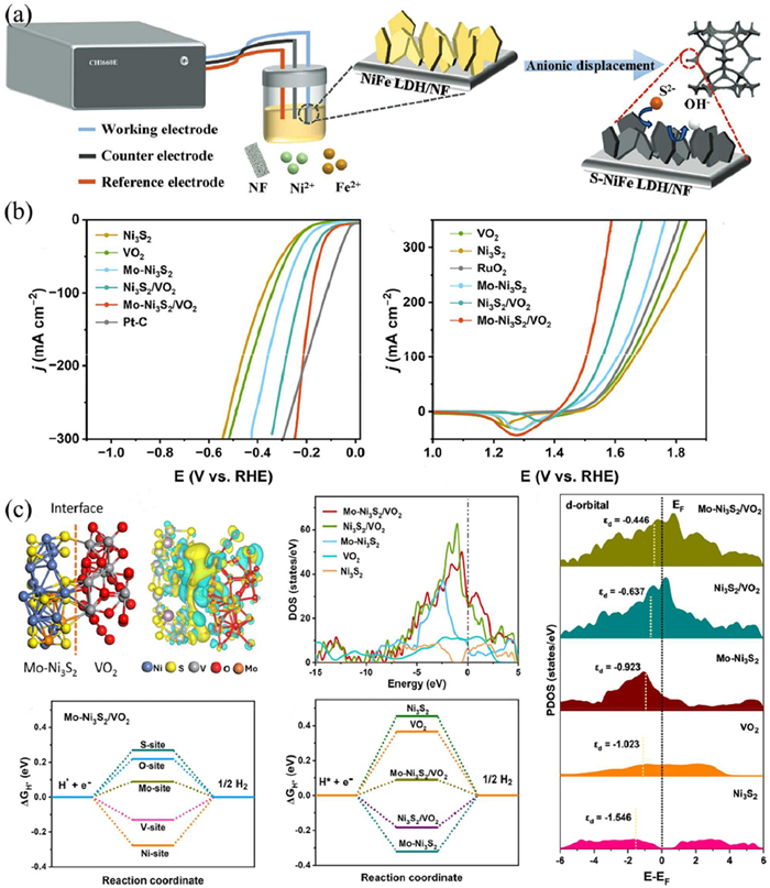
Chen et al. (Fig. 2a) synthesized sulfur-doped NiFe layered double hydroxide nanosheets (S-NiFe LDH) on a three-dimensional porous nickel foam substrate through electrochemical deposition and ion exchange strategies at room temperature [32]. The incorporation of S can enhance conductivity, promote structural reconfiguration, form highly active hydroxides, and improve the corrosion resistance of chloride ions. It can be used as a high-performance, highly selective, and durable OER electrocatalyst for seawater electrolysis at high current densities. As shown in Fig. 2b, the Mo-Ni3S2/VO2 catalyst synthesized by Dao et al. [33] through a one-step hydrothermal method has the best performance for both HER and OER, reaching 75 mV and 193 mV (10 mA/cm2). The DFT study (Fig. 2c) indicates that the Mo-Ni3S2/VO2 heterostructure shows a higher electron density near the Fermi level, which means that Mo-Ni3S2/VO2 has excellent conductivity and stronger electron mobility. Additionally, the d-band center of this catalyst is the closest to the Fermi level among the calculated materials. This suggests that the adsorption and desorption of intermediate products are favorable, and these findings indicate that Mo-Ni3S2/VO2 has excellent catalytic performance. Currently, researchers have discovered that incorporating rare earth elements as promoters into the catalyst can impart unique regulatory characteristics to the transition metal center, effectively optimizing the oxygen evolution reaction process. Liu et al. [34] synthesized an electrocatalyst by introducing Ce single-atom doping. DFT calculations and in-situ Raman analysis show that the Ce single-atom acts as an electron reservoir for the Ni site through the Ce-O-Ni chain during the OER process, establishing an efficient f-p-d electron transport channel. This is conducive to the occurrence of OER.
Figure 2
Figure 2.
(a) Schematic illustration depicting the fabrication route for S-NiFe LDH/NF. Copied with permission [32]. Copyright 2025, Wiley-VCH GmbH. (b) The LSV of Mo-Ni3S2/VO2 and (c) the DFT calculation. Reproduced with permission [33]. Copyright 2024, Elsevier B.V.
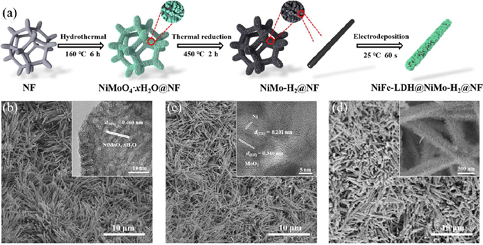
The site of the electrocatalytic water splitting reaction is confined to the surface of the catalyst, so the size and morphology of the catalyst will directly affect the exposure degree of the active sites and thus play a crucial role in its catalytic performance. Given the strong correlation between morphology and catalytic performance, optimizing the structural characteristics of the catalyst through morphology control has become an important means to improve its electrocatalytic activity. With the gradual maturity of advanced synthesis techniques, a series of nanostructured electrocatalysts with different dimensions have been successfully prepared, including zero-dimensional (0D) nanoparticles, one-dimensional (1D) nanowires/nanorods/nanowires, two-dimensional (2D) nanosheets, and three-dimensional (3D) nanoflowers, among others, providing a rich selection of structures for the performance optimization of electrocatalytic water splitting materials. The catalytic performance of LDHs-based electrocatalysts is closely related to the number of active sites and the mass transfer efficiency, and morphology control can achieve performance improvement by optimizing these key parameters. In the three-dimensional structure construction, Zhang et al. [35] designed a 3D composite structure consisting of foam nickel/nickel-based nanorods/NiFe-LDH nanosheets array (Fig. 3). Figs. 3b-d illustrate the successful construction of the NiFe-LDH@NiMo-H2@NF catalyst in a three-dimensional form. Through the synergistic expansion of the electrochemical active surface area by multi-level structures, the catalyst’s dual-function catalytic ability for HER and OER was significantly enhanced.
Figure 3
Figure 3.
Preparation and characterizations. (a) Schematic preparation route of NiFe-LDH@NiMo-H2@NF. SEM images of (b) NiMoO4·xH2O nanorods, (c) NiMo H2 nanorods, and (d) NiFe-LDH@NiMo-H2 grown on NF. Insets in (b) and (c) are corresponding HRTEM images and inset in (d) is local enlargement of SEM image. Reproduced with permission [35]. Copyright 2023, Tsinghua University Press.
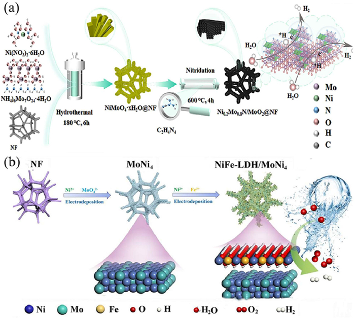
Heterogeneous structure construction is a key modification method in the design of electrocatalysts. By combining different functional components, the advantages of each component can be synergistically exerted, effectively compensating for the deficiencies of a single material in terms of the number of active sites, the exposure of edge sites, and the regulation of nanostructure. This significantly enhances the catalytic performance. Within the heterogeneous structure system, the electronic interaction between different components will lead to charge transfer or re-arrangement, thereby regulating the d-band center of the active sites. On the one hand, this can activate inert catalytic sites; on the other hand, it can optimize the electronic microenvironment of the active sites, ultimately achieving a synergistic improvement in catalytic performance. Lu et al. [36] constructed a hierarchical nanorod array heterogeneous structure catalyst of Ni0.2Mo0.8N/MoO2 (Fig. 4a). This catalyst integrates the high conductivity of Ni0.2Mo0.8 N and the chemical stability of MoO2, and through the strong metal-bridge interaction (SMSI), it not only accelerates the adsorption/dissociation kinetics of water molecules, optimizes the adsorption-desorption behavior of hydrogen intermediates (*H), but also effectively inhibits the dissolution of active components, significantly improving the charge transfer efficiency. For a single catalyst with excellent catalytic performance, the construction of heterogeneous structure is an effective strategy for further enhancing catalytic activity. The NiFe-LDH catalyst with excellent OER performance, although having poor HER performance, hinders its further application in water splitting. By constructing a heterogeneous structure with a catalyst with excellent HER performance, it can further promote its application in electrochemical water splitting. Zhao et al. [37] demonstrated that the NiFe-LDH/MoNi4/NF catalyst prepared through interface engineering strategies exhibited excellent HER performance (Fig. 4b). At a current density of 10 mA/cm2, this catalyst achieved 70 mV, which was lower than that of MoNi4 (73 mV) and NiFe-LDH (122 mV). The internal electric field formed at the heterogeneous interface regulates the electronic structure of the material, accelerating the electron transfer process. The d-band center analysis indicates that this strategy regulates the electron filling state of the anti-bonding orbitals of the catalyst, optimizes the adsorption energy of reaction intermediates, and thereby achieves an improvement in catalytic performance.
Figure 4
Figure 4.
(a) Schematic illustration of the synthetic process for the Ni0.2Mo0.8N/MoO2 heterostructure supported on the NF catalyst. Copied with permission [36]. Copyright 2025, Wiley-VCH GmbH. (b) Synthesis process. Copied with permission. Copied with permission [37]. Copyright 2026, Published by Elsevier B.V.
4.
Research status of nickel-based electrocatalysts
Among numerous applications, nickel-based materials have a promising application prospect in the field of hydrogen production through water electrolysis due to their unique electronic structure. Considering that the catalytic activity and stability of catalysts often show incompatibility in the same electrolyte, it is not the best choice to simply pair catalysts that only exhibit excellent HER or OER performance and use them for electrochemical total water hydrolysis. Only by fully leveraging the advantages of HER and OER electrocatalysts and combining them with the same material to construct an efficient bifunctional electrocatalyst, which has good binding capabilities with both hydrogen adsorption intermediates and oxygen-containing intermediates, is it possible to significantly enhance the overall catalytic activity of water splitting. Here, nickel-based hydroxides, nickel-based sulfides, nickel-based selenides and nickel-based phosphides are mainly introduced.
4.1
Nickel-based hydroxide
Layered double hydroxides (LDHs), a class of materials analogous to hydromagnesite, possess a layered framework constructed from hydroxide octahedra, where divalent cations (e.g., Ni2+, Co2+) or trivalent cations (e.g., Al3+, Fe3+) occupy the octahedral centers and interlayer spaces are filled with anions or water molecules [38].
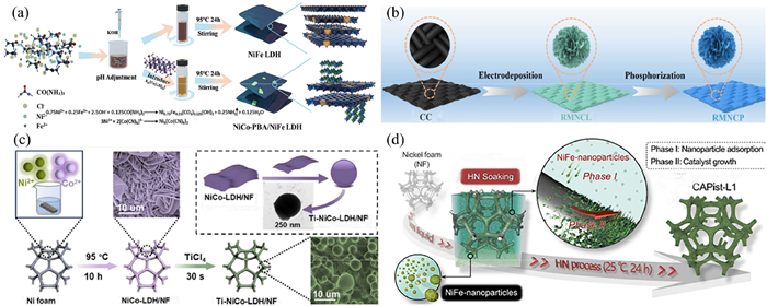
Nickel-based hydroxides have attracted much attention for their excellent OER properties [39,40]. Under alkaline conditions, they have good stability, are easy to synthesize, and the synthesis method, composition, and microstructure all can significantly affect their OER activity. However, their inherent conductivity is poor, and the layered structure is prone to overlap, which is not conducive to electron transfer and the exposure of active sites, thereby affecting the HER performance and limiting their application potential [41]. Zhang et al. constructed heterostructures through interface engineering, providing an effective idea for solving the surface reaction kinetics bottleneck of NiFe LDH (Fig. 5a) [42]. Ma et al. utilized doping and phosphination composites on NiCo-LDH to achieve the coordinated optimization of key parameters of catalytic reactions, promoting the development of the composite modification strategy for nickel-based hydroxides (Fig. 5b) [43]. Xie et al. introduced covalent bonds and oxygen vacancies through titanium doping to provide a new path for improving the electron transmission efficiency of LDH (Fig. 5c) [44]. Li et al. [45] developed a simple room-temperature preparation strategy, improving the catalytic stability while breaking through the limitations of traditional modification processes, laying the foundation for the large-scale application of LDH materials (Fig. 5d). These research results not only specifically solved the core application problems of LDH, but also promoted the overall research level of nickel-based hydroxide catalytic materials, clearly demonstrating the mainstream direction and important progress of the current modification research of nickel-based hydroxide materials.
Figure 5
Figure 5.
(a) Schematic diagram of one-pot synthesis for NiFe LDH and NiCo-PBA/NiFe LDH. Copied with permission [42]. Copyright 2025, Elsevier B.V. (b) Schematic diagram of synthesizing RMNCL and RMNCP. Copied with permission [43]. Copyright 2024, Elsevier B.V. (c) Schematic diagram of the process of exfoliating NiCo-LDH/NF nanosheets with TiCl4. Copied with permission [44]. Licensed under CC-BY. (d) Schematic of the preparation procedure for CAPist-L1 catalyst via a one-step HN process. Copied with permission [45]. Copyright 2024, Zhiheng Li et al.
Transition metal sulfides (TMSs) are regarded as promising bifurcative electrocatalysts due to their advantages such as high electrical conductivity, adjustable forms and multiple metal oxidation states [46]. Significant progress has been made in the field of water splitting, including MoS2 [47,48], Co9S8 [49], and Ni3S2 [50,51]. Among them, the hexagonal structure of Ni3S2, with its inherent metallic properties and abundant Ni-Ni bonds, is crucial for conductivity and electrocatalytic activity.
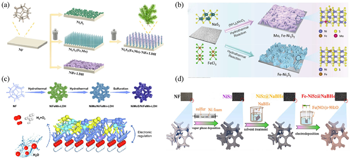
The research on nickel-based sulfides has gradually achieved a transition from basic modification to multi-element optimization. As shown in Figs. 6a and b, the relevant research by Zhao et al. [52] laid the foundation for the co-doping modification of nickel-based sulfides, while Sang et al. [53] simplified the preparation process and pushed this modification path towards practical application, improving the basic modification system of nickel-based sulfides. The research perspective shifted to composite modification technology. And in Fig. 6c, Mu et al. [54] innovatively combined doping and interface engineering, marking a new stage in the research of nickel-based sulfides from single modification to composite optimization, which is an important milestone in the research process. With the development of technology, the research on nickel-based sulfides has developed towards multiple mechanisms. Xiong et al. [55] innovatively proposed a multi-mechanism collaborative regulation idea, breaking through the limitations of traditional research, providing a new research perspective for the performance optimization of nickel-based sulfides, further enriching the modification theory and technology of nickel-based sulfides, and promoting new breakthroughs in the research progress (Fig. 6d). The above series of research results have laid a solid foundation for the high-performance design of nickel-based sulfide electrocatalysts and promoted the research and development of nickel-based sulfides in the field of electrocatalysis.
Figure 6
Figure 6.
(a) Preparation process of Ni3S2(Fe,Mo)-NiFe LDH. Copied with permission [52]. Copyright 2024, Elsevier B.V. (b) Schematic illustration of the fabrication process for Mo,Fe-Ni3S2. Copied with permission [53]. Copyright 2024, Elsevier B.V. (c) Synthesis process of materials structure of NiMoS/NFM-LDH. Copied with permission [54]. Copyright 2025, Elsevier B.V. (d) Schematic diagram of the Fe-NiS2@NaBH4 electrocatalyst synthesis process. Copied with permission [55]. Copyright 2025, American Chemical Society.
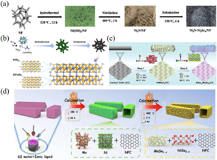
In recent years, transition metal selenides have become excellent candidates to replace noble metal catalysts due to their unique layered structure, high reactivity, narrow band gap, and abundant reserves [56]. Since selenium has better electrical conductivity than sulfur, transition metal selenides possess superior metallic properties, facilitating charge transfer and reaction progress. Consequently, research on nickel-based selenides in the field of water electrolysis catalysis has been made significant progress. Alemayehu et al. [57] conducted explorations of dual-site heterostructures, innovatively achieving the interface collaborative design of nickel-based sulfides and other metal compounds, laying the foundation for subsequent research on nickel-based sulfides (Fig. 7a). As the research progressed, the researchers continuously expanded the types and preparation paths of nickel-based sulfide heterostructures, promoting the research towards diversification and practicality. Mu et al. [58] innovatively combined preparation processes, using a combination of hydrothermal method and selenization method to enrich the material system of nickel-based sulfide heterostructures (Fig. 7b). Zhou et al. [59] further optimized the preparation process and loading form, synthesizing catalysts through a simple two-step hydrothermal method, simplifying the preparation process and promoting nickel-based sulfide catalysts towards convenient application (Fig. 7c). Additionally, as shown in Fig. 7d, Yi et al. [60] innovatively integrated multiple research strategies, breaking through the limitations of traditional single strategies, marking the research on nickel-based sulfides entering a new stage of multi-mechanism collaborative regulation, further expanding the research boundaries and technical paths of nickel-based electrocatalytic materials. These research results enriched the material system and modification techniques of nickel-based sulfides, promoting nickel-based sulfides towards practical application scenarios in electrocatalysis, and also providing a reference research idea for the development of other nickel-based diversified compound electrocatalytic materials.
Figure 7
Figure 7.
(a) Sample preparation and structural characterization of the Ni. Copied with permission [57]. Copyright 2025, Licensed under CC-BY 4.0. (b) Synthesis process of NiFeSe4/NiSe2. Copied with permission [58]. Copyright 2013, Royal Society of Chemistry. (c) Schematic illustration of the fabricating process of NiSe2−MoSe2/CC heterostructure catalyst. Copied with permission [59]. Copyright 2024, Elsevier B.V. (d) Illustration of the preparation process of MnSe1-x-NiSe2-x/NPC. Copied with permission [60]. Copyright 2025, Elsevier B.V.
Nickel-based phosphides have emerged as promising non-precious metal electrocatalysts for the hydrogen evolution reaction (HER), thanks to their unique crystal/electronic structures, mature synthesis, low cost, and favorable HER activity. The high electronegativity of P atoms enables them to abstract electrons from adjacent metals, forming negatively charged proton-accepting sites for HER. Their diverse elemental ratios make them the largest category of transition metal phosphides, and their distinctive band structures optimize conductivity and intermediate adsorption/desorption energy. Moreover, the large atomic radius of P induces lattice distortion and unsaturated coordination sites, exposing more active centers.
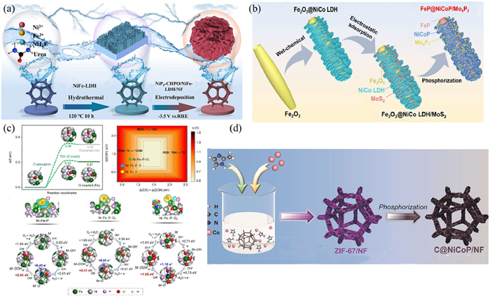
As the research progressed, the researchers continuously delved deeper into the study of the catalytic activity of nickel-based phosphides. Qiu et al. [61] synthesized the catalyst in a simple way (Fig. 8a), and at the same time, they used DFT calculations to prove that the synergy between nickel and phosphorus could optimize the interface water structure, revealing the active essence of nickel-based phosphides in the HER process. At the same time, the researchers continuously expanded the preparation paths and modification strategies of nickel-based phosphides, enriching the research system. Yang et al. [62] innovatively proposed the “electronic island” micro-interface engineering strategy (Fig. 8b), through the collaborative design of multi-component interfaces, breaking through the limitations of traditional single-interface regulation, establishing a new micro-interface regulation system, and further improving the research system and technical path of nickel-based phosphides. The Wu team [63] innovated the research method combination, combining in-situ Q-XAFS technology and electrochemical control means, and at the same time, using DFT calculations in Fig. 8c for verification, revealing the active essence of nickel-based phosphides in the OER process, further enriching the research mechanism of nickel-based phosphides catalysis. Shi et al. [64] innovatively selected the precursor, using MOF as the precursor, successfully preparing carbon-coated bimetallic phosphide catalysts (Fig. 8d), broadening the preparation ideas and modification paths of nickel-based phosphides. These series of research results achieved multi-dimensional breakthroughs in the field of nickel-based phosphides research, providing solid theoretical support and experimental basis for the subsequent research on high-performance nickel-based phosphide catalysts, and also providing a reference technical path and research idea for the research of similar transition metal phosphides, continuously promoting the overall development of transition metal phosphide electrocatalytic materials.
Figure 8
Figure 8.
(a) Schematic illustration of the synthesis process of NiP2-CHPO/NiFe-LDH/NF. The aforementioned experiments were repeated three times. Copied with permission [61]. Copyright 2025, Elsevier B.V. (b) Schematic illustration of the synthesis process of FeP@NiCoP/Mo4P3. Copied with permission [62]. Copyright 2025, Wiley-VCH GmbH. (c) The DFT calculation. Copied with permission [63]. Copyright 2025, Licensed under CC-BY. (d) Structural and morphological characterization of C@NiCoP/NF. Copied with permission [64]. Copyright 2025, Elsevier B.V.
In addition to the common nickel-based hydroxides, sulfides, selenides and phosphides, significant progress has been made in the research of new nickel-based catalytic materials. Among them, nickel-based carbides and nitrides are typical representatives, while the MXene materials of the transition metal carbon/nitrogen family are the research hotspots of new electrocatalytic materials.
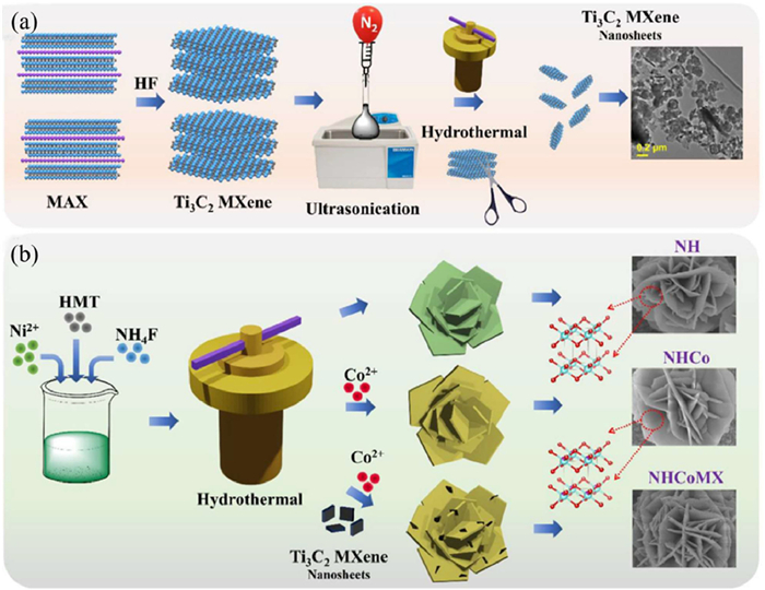
Nickel-based carbides have a metal framework and carbon atoms are embedded in the interstitial sites. Due to the advantages of high conductivity and excellent corrosion resistance and structural stability of nickel-based carbides, they show good catalytic application prospects in HER [66]; nickel-based nitrides, with excellent conductivity and chemical stability, have become highly potential electrocatalytic materials. The DFT calculation results show that the introduction of nitrogen atoms can significantly increase the d electron density, through the d band contraction effect to increase the density of states near the Fermi level, making its electronic structure similar to that of the noble metals Pd and Pt. In addition, the new two-dimensional layered crystal material MXene with a graphite-like structure, due to its unique interlayer characteristics and excellent electrochemical properties such as conductivity, layered structure, hydrophilicity and mechanical stability, determines its broad application prospects in the field of electrocatalysis. Amaranadha et al. [65] synthesized an electrocatalyst Ti3C2 MXene nanosheets integrated with cobalt-doped nickel hydroxide (NHCoMX) composite by hydrothermal method (Figs. 9a and b). The rich pores in the integrated microstructure of Ti3C2 MXene nanosheets (MX) increase the number of active sites, promote charge transfer, and thereby enhance electrocatalysis.
Figure 9
Figure 9.
Schematic illustration of (a) synthesis of Ti3C2 MXene nanosheets. (b) synthesis of heterostructured Ti3C2 MXene-integrated cobalt-doped nickel. Copied with permission [65]. Copyright 2025, Licensed under CC-BY.
Hydroelectric water electrolysis technology can be broadly classified into three categories: Alkaline water electrolysis (alkaline water electrolysis, AWE), proton exchange membrane water electrolysis (proton exchange membrane water electrolysis, PEMWE), and anion exchange membrane water electrolysis (anion exchange membrane water electrolysis, AEMWE) [67]. Each system has its unique advantages and faces specific challenges. Compared with the traditional AWE, AEMWE, as a new type of water electrolysis cell, not only retains the advantages of PEMWE in using solid polymer electrolytes and zero-gap structure, but also its alkaline environment allows the use of inexpensive metal catalysts and plate materials, and is considered as the next-generation key research and development of renewable energy water electrolysis for hydrogen production [68-70]. AEMWE is mainly composed of bipolar plates, flow channels, and membrane electrodes, and the membrane electrode is the key place where the water electrolysis reaction occurs [71]. Different from the simple HER surface reaction behavior in traditional AWE systems, in AEMWE, the transport behavior of OH− and the interface microenvironment of the catalyst layer/ionic conductor of anion exchange ion conductor/membrane are the key factors regulating the HER performance of nickel-based catalysts [72].
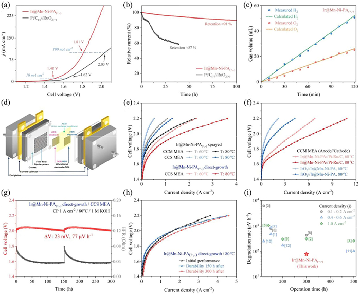
Based on the alkaline environment advantages of AEMWE and the core role of nickel-based catalysts in regulating the performance of hydrogen evolution reaction (HER), the research on nickel-based materials in alkaline anion exchange membrane water electrolyzers is currently deepening continuously and has achieved a series of breakthrough results. Quynh et al. [73] synthesized an Ir@Mn-Ni-PA catalyst, which exhibited excellent bifunctional activity. At a current density of 10 mA/cm2, the overpotential for HER was only 65 mV, and the overpotential for OER was 272 mV, with stability exceeding 100 h. As shown in Fig. 10, When applied in a single cell of AEMWE, at a voltage of 2.0 V and at temperatures of 60 ℃ and 80 ℃, current densities of 1.11 and 1.64 A/cm2 were achieved respectively, and stable operation for 300 h was maintained under industrial-related conditions.
Figure 10
Figure 10.
Electrochemical performance of the overall water splitting and AEMWE. Copied with permission [73]. Copyright 2026, Licensed under CC-BY.
Nickel-based transition metal nanomaterials and their structural electrodes show great potential in bifunctional water electrolysis catalysis. With advantages of abundant reserves and environmental benignity, they have broad development prospects. The morphology and electronic structure of nickel-based catalysts can be effectively tailored by strategies like heterostructure construction, porous regulation, core-shell design, and multiphase interface engineering. Additionally, cation-anion co-doping enables synergistic modulation of electronic states, further enhancing catalytic performance.
However, large-scale commercial application of nickel-based electrocatalysts still faces challenges, including synthesis process scalability, catalytic activity, and durability under high current density, and stability in complex reaction environments.
Future research should not only explore the intrinsic nature of active sites and reaction mechanisms in HER, OER, and overall water splitting, but also focus on realizing the coordinated integration of “large-scale production”, “low energy consumption," and "high stability” in large-scale green hydrogen production systems. Specific development directions include:
(1) Mechanism research deepening: Advanced in-situ characterization and theoretical simulations can elucidate the structural evolution and dynamic behaviors of active sites under actual reaction conditions, clarify reaction pathways and deactivation mechanisms, and lay a foundation for rational design of high-performance nickel-based electrocatalysts.
(2) Application scenario expansion: Actively develop adaptive catalyst systems suitable for various water qualities (such as seawater, freshwater, even wastewater) and complex environments, expand the applicable boundaries of electrolysis water hydrogen production technology, and enhance its ability to cope with actual scenarios. In the future, the focus will be on two core scenarios: Seawater electrolysis and industrial-grade hydrogen production. Promote the technological iteration and scenario adaptation of nickel-based catalysts and achieve the leap from laboratory performance to industrial application capabilities. In the field of seawater electrolysis, focus on developing nickel-based catalyst systems suitable for future large-scale seawater electrolysis. Through multiple strategies such as doping, morphology control, and hetero-interface engineering, effectively inhibit chlorine evolution side reactions and catalyst corrosion, significantly improve the long-term stability and catalytic selectivity of the catalyst in high-salt and fluctuating water quality environments, providing core material support for the large-scale construction of marine green hydrogen bases in the future; in the industrial application field, guided by the actual needs of future industrial-grade hydrogen production, continuously advance catalyst performance upgrades, focus on breaking through the industry pain points of rapid catalytic activity decline and high energy consumption at high current densities (≥500 mA/cm2), and strengthen the durability of the catalyst during long-term continuous operation. In addition, hybrid electrolysis technologies such as UOR and SOR can be adopted, where the anode substitution reactions replace the traditional OER to prevent chlorine evolution side reactions from occurring while also treating industrial wastewater, making it more suitable for complex water quality electrolysis scenarios such as industrial wastewater and industrial by-product water. At the same time, in line with the development trends of future scalable technologies, integrate modular and lightweight concepts into catalyst design to promote the research and development of the adaptability of catalysts and large-scale electrolyzers, facilitating the modular construction of electrolysis water hydrogen production systems and flexible capacity expansion, further expanding the applicable boundaries of electrolysis water hydrogen production technology, and laying the foundation for the preparation of green hydrogen in multiple scenarios and on a large scale in the future.
(3) System coupling and integration: Efficiently couple water electrolysis systems with renewable energy (e.g., solar, wind energy), develop intelligent dispatching and energy management strategies to overcome renewable energy intermittency, improve hydrogen production economic efficiency, and increase the proportion of green hydrogen.
Breakthroughs in material design, system integration, and energy management are essential to mature water electrolysis hydrogen production technology and accelerate the large-scale application of hydrogen energy as a clean energy source.
Declaration of competing interest
We declare that we do not have any commercial or associative interest that represents a conflict of interest in connection with the work submitted.
Acknowledgments
This work was supported by the China Postdoctoral Science Foundation (No. 2024M752352), supported by the Jinan City-School Integration Development Strategy Project (No. JNSX2023015).
[1]
J.M.V. Nsanzimana, L. Cai, A. Djire, et al., Adv. Energy Mater. 15 (2025) 2501686. doi: 10.1002/aenm.202501686
[2]
L. Xu, L. Zheng, Y. Xu, et al., J. Colloid Interface Sci. 679 (2025) 109–118. doi: 10.1016/j.jcis.2024.09.238
[3]
R. Ramos, K.T. Pham, R.C. Prince, et al., Science 387 (2025) eads9960. doi: 10.1126/science.ads9960
S. Mishra, S. Mishra, V. Sharma, et al., J. Mater. Chem. A 14 (2026) 9033–9045. doi: 10.1039/d5ta08482b
[73]
Q.P. Ngo, S.Y. Paek, J.Y. Lee, et al., Adv. Energy Mater. 16 (2026) e06645. doi: 10.1002/aenm.202506645
Figure 1
(a) Production costs for grey hydrogen, blue hydrogen and green hydrogen from 2020 to 2050, where the solid lines are the average costs, and the dashed lines are the optimal costs. Copied with permission [6]. Copyright 2023, Royal Society of Chemistry. (b) Hydrogen evolution reaction (HER) and oxygen evolution reaction (OER) of electrocatalytic water splitting. Reproduced with permission [21]. Copyright 2021, Elsevier B.V. (c) Schematic illustration of AEM pathways for the OER under acidic and alkaline/neutral conditions. Schematic illustration of LOM pathways for OER on oxygen site and metal site. Reproduced with permission [29]. Copyright 2013, Royal Society of Chemistry. (d) The typical HER and OER polarization curves. η10 represents the overpotential that required to achieve a current density of 10 mA/cm2. Reproduced with permission [31]. Copyright 2021, Wiley-VCH GmbH.
Figure 2
(a) Schematic illustration depicting the fabrication route for S-NiFe LDH/NF. Copied with permission [32]. Copyright 2025, Wiley-VCH GmbH. (b) The LSV of Mo-Ni3S2/VO2 and (c) the DFT calculation. Reproduced with permission [33]. Copyright 2024, Elsevier B.V.
Figure 3
Preparation and characterizations. (a) Schematic preparation route of NiFe-LDH@NiMo-H2@NF. SEM images of (b) NiMoO4·xH2O nanorods, (c) NiMo H2 nanorods, and (d) NiFe-LDH@NiMo-H2 grown on NF. Insets in (b) and (c) are corresponding HRTEM images and inset in (d) is local enlargement of SEM image. Reproduced with permission [35]. Copyright 2023, Tsinghua University Press.
Figure 4
(a) Schematic illustration of the synthetic process for the Ni0.2Mo0.8N/MoO2 heterostructure supported on the NF catalyst. Copied with permission [36]. Copyright 2025, Wiley-VCH GmbH. (b) Synthesis process. Copied with permission. Copied with permission [37]. Copyright 2026, Published by Elsevier B.V.
Figure 5
(a) Schematic diagram of one-pot synthesis for NiFe LDH and NiCo-PBA/NiFe LDH. Copied with permission [42]. Copyright 2025, Elsevier B.V. (b) Schematic diagram of synthesizing RMNCL and RMNCP. Copied with permission [43]. Copyright 2024, Elsevier B.V. (c) Schematic diagram of the process of exfoliating NiCo-LDH/NF nanosheets with TiCl4. Copied with permission [44]. Licensed under CC-BY. (d) Schematic of the preparation procedure for CAPist-L1 catalyst via a one-step HN process. Copied with permission [45]. Copyright 2024, Zhiheng Li et al.
Figure 6
(a) Preparation process of Ni3S2(Fe,Mo)-NiFe LDH. Copied with permission [52]. Copyright 2024, Elsevier B.V. (b) Schematic illustration of the fabrication process for Mo,Fe-Ni3S2. Copied with permission [53]. Copyright 2024, Elsevier B.V. (c) Synthesis process of materials structure of NiMoS/NFM-LDH. Copied with permission [54]. Copyright 2025, Elsevier B.V. (d) Schematic diagram of the Fe-NiS2@NaBH4 electrocatalyst synthesis process. Copied with permission [55]. Copyright 2025, American Chemical Society.
Figure 7
(a) Sample preparation and structural characterization of the Ni. Copied with permission [57]. Copyright 2025, Licensed under CC-BY 4.0. (b) Synthesis process of NiFeSe4/NiSe2. Copied with permission [58]. Copyright 2013, Royal Society of Chemistry. (c) Schematic illustration of the fabricating process of NiSe2−MoSe2/CC heterostructure catalyst. Copied with permission [59]. Copyright 2024, Elsevier B.V. (d) Illustration of the preparation process of MnSe1-x-NiSe2-x/NPC. Copied with permission [60]. Copyright 2025, Elsevier B.V.
Figure 8
(a) Schematic illustration of the synthesis process of NiP2-CHPO/NiFe-LDH/NF. The aforementioned experiments were repeated three times. Copied with permission [61]. Copyright 2025, Elsevier B.V. (b) Schematic illustration of the synthesis process of FeP@NiCoP/Mo4P3. Copied with permission [62]. Copyright 2025, Wiley-VCH GmbH. (c) The DFT calculation. Copied with permission [63]. Copyright 2025, Licensed under CC-BY. (d) Structural and morphological characterization of C@NiCoP/NF. Copied with permission [64]. Copyright 2025, Elsevier B.V.


 DownLoad:

 下载:
下载:


 下载:
下载:

