Citation:
Yaoce Wang, Keyu Zhang, Xinyu Jiang, Binbin Li, Bo Jin, Juan Yang, Xiangyang Zhou, Bin Yang, Yaochun Yao. Micron silicon anodes for superior lithium storage: A view from chemical-mechanical degradation mechanisms to interface electrolyte systematic design[J]. Chinese Chemical Letters,
2026, 37(9): 112631.
doi:
10.1016/j.cclet.2026.112631
Micron silicon anodes for superior lithium storage: A view from chemical-mechanical degradation mechanisms to interface electrolyte systematic design
English
Micron silicon anodes for superior lithium storage: A view from chemical-mechanical degradation mechanisms to interface electrolyte systematic design
National Engineering Research Center of Vacuum Metallurgy, Faculty of Metallurgy and Energy Engineering, Kunming University of Science and Technology, Kunming 650093, China
b.
Southwest United Graduate School, Kunming 650091, China
c.
School of Metallurgy and Environment, Central South University, Changsha 410083, China
Received Date:
11 December 2025 Accepted Date:
16 March 2026 Revised Date:
04 March 2026 Available Online:
15 September 2026
Abstract:
Silicon is considered as one of the most promising anodes for next-generation lithium-ion batteries (LIBs) due to its high theoretical specific capacity (3579 mAh/g) and abundant natural reserves. Compared to nano silicon, micron silicon offers distinct advantages, including lower specific surface area, reduced interfacial side reactions, higher initial coulombic efficiency, greater tap density, and lower cost, making it highly attractive for practical applications. However, its commercial viability is hindered by severe volume expansion, localized stress accumulation, repeated formation of unstable solid electrolyte interphase (SEI) layers, and electrical disconnection during cycling, which together result in rapid capacity fading and high irreversible capacity loss. Recent advances in electrolyte engineering, particularly interfacial modification strategies, have significantly improved the performance of micron silicon anodes by mitigating these challenges. This review provides an integrated perspective on the application of micron-sized silicon anodes by correlating lithium storage mechanisms, failure behaviors, and electrolyte-electrode interfacial evolution. Based on a systematic discussion of silicon lithiation/delithiation processes and associated structural instability, we clarify how interfacial degradation and irreversible lithium consumption govern the electrochemical performance of micron silicon. Then, electrolyte optimization strategies are critically analyzed, with an explicit comparison between liquid electrolyte regulation and solid-state electrolyte (SSE) design, highlighting their distinct roles in interfacial stabilization, stress accommodation, and cycling durability. From an electrolyte system design standpoint, this review summarizes integrated design principles for improving micron silicon performance and discusses the remaining challenges and opportunities toward their commercial application in high-energy-density battery systems.
Driven by the global energy transition and carbon neutrality goals [1], the urgency of addressing climate change has accelerated innovation in green energy technologies worldwide [2]. As the core energy carriers in electric vehicles [3] and large-scale energy storage systems [4], LIBs play a critical role in advancing the energy revolution and achieving sustainable development [5–7]. However, the widely commercialized graphite anodes, limited by theoretical specific capacity of only 372 mAh/g, can no longer satisfy the ever-increasing demands for high energy density and extended driving range [8]. Against this backdrop, silicon, with its ultrahigh theoretical specific capacity of 3579 mAh/g (≈9.6 times that of graphite) [9], together with advantages such as abundance, low cost, and environmental benignity, has been identified as an ideal next-generation anode material for LIBs [10]. Its development and deployment are well aligned with the urgent global demand for advanced energy storage technologies in a low-carbon economy [11–13].
Research on silicon-based anodes dates back to the 1970s [14], yet early progress was hindered by silicon's intrinsically low electrical conductivity and poor cycling stability [15], preventing its full electrochemical potential from being realized [16,17]. A turning point came in 1999, when Li and co-workers reported that nano-silicon exhibited superior cycling performance [18], which inspired subsequent research trends focusing on nanoscale silicon materials. Nevertheless, nano-Si undergoes drastic volumetric fluctuations (~300%) during lithiation/delithiation, leading to electrode pulverization and rapid capacity fading [19]. To address this, carbon-based composite strategies, such as Si/carbon nanotubes [20,21] and Si/graphene hybrids, were widely explored, effectively enhancing electrode conductivity and mechanical resilience [22], and laying an important foundation for further modification of silicon anodes. However, nano-Si still faces critical barriers to commercialization. Its preparation process often results in severe particle agglomeration and low tap density, which not only reduce the utilization of active material, but also aggravate interfacial impedance and promote uneven SEI formation, further accelerating performance degradation [23].
In this context, micron silicon (μSi) has recently attracted renewed research interest owing to its high tap density, lower specific surface area, mitigated interfacial side reactions [24], and cost-effectiveness [25]. These features grant μSi strong industrial applicability and scalability [26,27]. However, μSi anodes suffer from extreme and largely irreversible volume expansion (up to 300%−400%) during lithiation, triggering a cascade of critical issues. The violent expansion induces particle fracture and electrode structural collapse; mechanically unstable solid electrolyte interphase (SEI) layers continuously crack and reform under stress, consuming electrolyte and active lithium, which reduces coulombic efficiency and shortens cycle life [28]. In addition, the intrinsically low electrical conductivity of silicon (≈10−4 S/cm at room temperature) further compromises rate performance [29].
As visually summarized in the roadmap (Fig. 1), the evolution of silicon anodes has undergone a distinct logical transition [16]. Early research (1970s-1990s) primarily focused on understanding the fundamental lithiation mechanism and failure modes [17,30]. This was followed by a "nano-era" (early 2000s) [31], where nano-structuring was the dominant strategy to mitigate particle pulverization [32,33]. However, recognizing the limitations of nano-silicon in volumetric energy density and cost [34], the field has witnessed a paradigm shift back to μSi since roughly 2013, emphasizing structural engineering and interface modification. Most notably, the current timeline (2020-present) highlights a critical transition from liquid to solid-state systems [35,36]. This shift aims to leverage the intrinsic safety and mechanical suppression capabilities of solid-state electrolytes (SSEs) to fundamentally resolve the unstable SEI issues inherent to μSi [37,38]. Overall, electrolyte engineering has emerged as a pivotal solution. To systematically address the aforementioned challenges, diverse modification approaches have been proposed, which can be categorized as follows: (1) Structural engineering of μSi anodes, designing three-dimensional porous Si-based alloy frameworks to accommodate volume expansion and suppress lithium dendrite growth during cycling [39]; (2) Compositional modification of Si anodes, including composite electrode design [40], advanced binders [41,42], optimized conductive agents [43], and prelithiation strategies [44], all of which aim to reinforce the conductive network and reduce parasitic interfacial reactions; (3) Liquid electrolyte design, through rational regulation of additives [45], lithium salts [46], and solvents [44], to optimize lithiation/delithiation reactions, minimize interfacial resistance, and stabilize the SEI layer; (4) SSEs development, as an emerging focus in recent years, solid electrolytes, with their high mechanical strength and chemical stability [47], effectively suppress Si volume expansion while eliminating flammability concerns of liquid electrolytes, thereby markedly improving both safety and stability of battery systems [48].
Figure 1
Figure 1.
Development timeline of micron silicon and key technology advances. The early stage primarily focused on understanding the phase evolution, lithiation/ delithiation mechanisms, and structural degradation of Si. Reproduced with permission [16]. Copyright 1976, The Electrochemical Society. Reproduced with permission [17]. Copyright 1981, The Electrochemical Society. Reproduced with permission [18]. Copyright 1999, The Electrochemical Society. Reproduced with permission [30]. Copyright 2003, The Electrochemical Society. Reproduced with permission [31]. Copyright 2004, The Electrochemical Society. Subsequent efforts emphasized improving electrochemical performance through composite design and structural regulation. Reproduced with permission [32]. Copyright 2006, Elsevier. Reproduced with permission [33]. Copyright 2009, Elsevier. Reproduced with permission [34]. Copyright 2013, Springer Nature. Reproduced with permission [35]. Copyright 2015, Elsevier. In recent years, research has progressively shifted toward electrolyte engineering, including liquid electrolyte modification (additives, lithium salts, and solvents) and solid-state electrolyte design targeting volume accommodation and interfacial stabilization. Reproduced with permission [36]. Copyright 2020, Springer Nature. Reproduced with permission [37]. Copyright 2021, AAAS. Reproduced with permission [38]. Copyright 2025, Springer Nature.
In this review, we present a systematic review of electrolyte design and optimization strategies for μSi anodes in both liquid and solid-state systems. We begin by revisiting the fundamental lithiation mechanism of Si and analyzing the irreversible failure pathways that occur during cycling, thereby establishing targeted principles for electrolyte system design. Subsequently, we comprehensively summarize the latest advancements in both liquid and SSEs tailored for μSi anodes. With the rapid evolution of solid-state battery technologies, the development trajectory of μSi-based anodes has undergone significant transformation. Finally, we discuss the commercial prospects, potential challenges, and strategic perspectives for achieving compatibility between μSi anodes and diverse electrolyte systems. By critically analyzing the key challenges in current electrolyte modification strategies, this review provides valuable guidance for the future design and application of electrolyte systems in μSi-based anode materials.
2.
Lithium storage and failure mechanisms of silicon anodes
A clear understanding of the lithiation-delithiation process and the associated Li-Si alloying reactions is essential for the development of silicon anode materials, as it directly governs performance optimization and practical applications [49]. Investigations into the lithium storage mechanism enable deeper insights into the phase transformations, volume expansion, and interfacial interactions with electrolytes during cycling [50], thereby guiding the rational design of advanced Si-based anodes, optimized electrode architectures, and tailored electrolyte formulations. Such understanding is crucial for improving key performance metrics, including cycle life, rate capability, and coulombic efficiency [51], which are indispensable for the practical implementation of Si anodes in LIBs. However, the alloying process also introduces critical challenges, including drastic volume changes, electrical disconnection, and repeated rupture/regeneration of the SEI [52], all of which severely compromise cycling stability and electrochemical performance [53].
2.1
Lithium storage mechanism
According to the Li-Si binary phase diagram (Fig. 2a), multiple voltage plateaus are expected during Li insertion into silicon at elevated temperatures [54]. However, under ambient conditions, crystalline Si undergoes a rapid crystalline-to-amorphous phase transition during the first lithiation cycle [55,56] and remains amorphous in subsequent cycles. Wen et al. [57] demonstrated via galvanostatic intermittent titration technique (GITT) that at 415 ℃, lithium insertion follows the thermodynamically stable sequence of Li12Si7 → Li7Si3 → Li13Si4 → Li22Si5, with each intermediate phase being thermodynamically stable. In practical applications, however, the operating temperature of Si anodes does not reach such levels, and the highest lithiation phase observed remains Li15Si4 [58,59]. Furthermore, the delithiation process of crystalline silicon exhibits strong crystallographic anisotropy, leading to pronounced differences in volume change across different lattice orientations [60]. During lithiation, crystalline Si expands most significantly along the 〈110〉 direction, producing a flat LixSi/Si reaction front parallel to the {110} plane that propagates inward toward the unreacted crystalline Si core, which assumes a near-hexagonal morphology. It is noteworthy that in Si/carbon composites, the lithiation behavior of Si exhibits distinct electrochemical features compared with pure Si. Specifically, Si undergoes transitions among various amorphous states, as opposed to crystalline-amorphous transformations [61], particularly in the plateau regions associated with Si-Li conversion reactions [62].
Figure 2
Figure 2.
(a) Si electrochemical lithiation and delithiation curve at room temperature and high temperature. Reproduced with permission [54]. Copyright 2012, Elsevier. (b) Phase diagram describing the phase changes of Si during the charge-discharge cycling in Si@SC and Si@HC respectively. Reproduced with permission [66]. Copyright 2024, Elsevier. (c) Schematic diagram of lithium diffusion mechanism. Reproduced with permission [65]. Copyright 2025, Elsevier. (d) Schematic open-circuit energy diagram of an electrolyte. Reproduced with permission [70]. Copyright 2019, The Royal Society of Chemistry. (e) XRR of lithiated Si fit-derived electron density profiles and galvanostatic electrochemistry. Reproduced with permission [74]. Copyright 2017, Wiley-VCH.
Overall, the lithiation/delithiation reactions of Si involve multiple phase transformations corresponding to distinct voltage plateaus, each associated with different Li-Si stoichiometries [63,49]. During the initial lithiation, crystalline Si gradually transforms into amorphous LixSi as Li+ migrates inward [64]. When the electrode is deeply lithiated to ≈0.05 V, in situ XRD electrochemical coupled measurements reveal the sharp emergence of Li3.75Si diffraction peak at 2θ ≈ 24°, corresponding to the 50 mV plateau in the differential capacity (dQ/dV) profile. Xue et al. [65] reported that hard carbon-silicon composites (Si@HC) exhibit deeper lithiation into amorphous Li-Si states below 0.4 V (Fig. 2b), further demonstrating the role of carbon in stabilizing amorphous lithiation pathways. Wang et al. [66] demonstrated that introducing trace oxygen atoms via an oxygen-vacancy gradient (Fig. 2c) shifts the Gibbs free energy of Li15Si4 formation from negative to positive, thereby completely suppressing crystalline phase formation and ensuring the lithiation products remain amorphous. This strategy significantly reduces stress-phase coupling, enabling highly stable lithium storage behavior with 97% capacity retention after 1000 cycles. In oxygen-gradient-doped microspheres, the characteristic Li15Si4 diffraction peak is absent throughout discharge, replaced by a broadened feature at 480 mV, confirming the suppression of crystalline Li-Si phases and preservation of amorphous products, fundamentally mitigating fracture induced by phase-stress coupling. Additionally, the incorporation of carbon significantly influences the lithium storage mechanism.
In-depth studies of the lithium storage mechanism have revealed that the size effect plays a decisive role in dictating the electrochemical behavior of silicon anodes. Once the particle size of silicon exceeds a critical threshold, its lithiation dynamics and electrochemical stability are markedly altered [67,68]. The size effect not only impacts the overall performance of silicon anodes, but also significantly influences the formation and stability of SEI. Quantitatively, the high specific surface area of nano-Si leads to a significantly higher absolute mass of SEI formation during the initial cycles, resulting in low initial Coulombic efficiency. However, the SEI on nano-Si tends to be more compositionally homogeneous, often dominated by organic carbonates and semi-carbonates due to extensive surface contact with the solvent. In contrast, μSi exhibits a distinct interfacial evolution mechanism. A recent benchmarking study by Wu et al. [69] provided quantitative insights into the distinct interfacial evolutions of nano- and micro-silicon. Contrary to the assumption that μSi accumulates thicker SEI due to cracking, their synchrotron-based soft X-ray absorption spectroscopy (sXAS) revealed that nano-silicon actually develops a significantly thicker SEI layer compared to μSi. Due to its immense specific surface area, nano-silicon triggers severe parasitic reactions, forming a thick, LiF-rich passivation layer that persists throughout cycling. This excessive SEI growth increases interfacial impedance and consumes electrolyte, serving as the primary failure mode for nano-silicon. In contrast, μSi maintains a relatively thinner SEI layer, characterized by a diminishing LiF content and strong signals of lithium silicates (LixSiOy) and organic species upon cycling. However, despite the thinner SEI, μSi suffers from catastrophic mechanical failure, where particle pulverization and "popcorn-like" structural expansion lead to electrical isolation. Thus, the size effect dictates a trade-off: Nano-silicon is limited by interfacial electrochemical instability (thick SEI), whereas μSi is limited by bulk mechanochemical disintegration.
The SEI represents a critical interfacial component in LIBs. When the lowest unoccupied molecular orbital (LUMO) of organic solvents or lithium salts lies below the Fermi level of the anode, electrons from the anode reduce these electrolyte species, forming a passivation layer-SEI (Fig. 2d) [70]. Functionally, the SEI inhibits electron transport while remaining permeable to lithium ions [71], thus regulating interfacial kinetics. Its mechanical and electronic properties strongly affect Li+ diffusion across the Si interface. Typically, the organic-rich outer layer exhibits higher resistance, whereas the inorganic-rich inner layer provides faster Li-ion conduction. Force spectroscopy mapping of discharged Si anodes has revealed the highly heterogeneous mechanical properties of SEI layers, with softer regions corresponding to organic-rich outer domains. While distinct layered architectures and Young's modulus distributions can be clearly distinguished. Atomistic insights into SEI formation have been provided by simulation studies. Yun et al. [72] employed reactive force field (ReaxFF) simulations to investigate electrolyte decomposition on Si surfaces, showing that ethylene carbonate (EC) undergoes ring-opening reactions to form gaseous by-products (C2H4, CO) and subsequently produces inorganic salts (Li2CO3, Li2O) as well as organic species (ROCO2Li). On surface of SiOx, oxygen passivation reduces gas evolution. But, functional additives, such as vinylene carbonate (VC) and fluoroethylene carbonate (FEC) preferentially, react with electrolyte molecules to tailor the SEI composition and morphology, thereby enhancing electrochemical performance. This work provides atomic-level evidence for SEI formation mechanisms and establishes a design rationale for next-generation electrolytes and additives. Cao et al. [73] further employed sub-angstrom resolution techniques to reveal potential-dependent SEI bilayer growth on single-crystalline Si/SiO2 anodes. At ~0.7 V, native SiO2 is lithiated to form a LixSiOy-rich "inner-SEI", whereas upon further polarization to ~0.6 V, electrolyte decomposition occurs on this surface, depositing an LiF-dominated "outer-SEI". Notably, the sequential bilayer growth dictates both ionic/electronic transport across the interface and the extent of initial capacity loss. Complementary density functional theory (DFT) studies by Wang et al. [74] probed the interfacial characteristics of LiF/LixSi systems under lithiation and deformation, revealing that LiF and LixSi phases can withstand substantial strain. Stable nanopores develop homogeneously across the LiF and LixSi matrices and their interfaces, inducing pronounced stress-strain softening (Fig. 2e). Compared with Li2O/LixSi interfaces, LiF/LixSi interfaces exhibit significantly greater ductility. Importantly, the chemical composition of the SEI critically determines electrochemical performance. When weakly coordinating anions (e.g., LiPF6, LiTFSI, LiClO4) are employed, Si anodes exhibit high coulombic efficiency, favorable capacity retention, and low impedance. Conversely, strong-coordinating salts, such as LiBF4 lead to poor capacity retention, low coulombic efficiency, and high interfacial resistance.
2.2
Failure analysis
The failure mechanisms of silicon anodes during lithiation and delithiation can be analyzed from both kinetic and thermodynamic perspectives [24,49]. Kinetic failure is primarily associated with the severe mechanical stress and large volume variations that occur during charge-discharge cycling (Figs. 3a and b), which restrict electron/ion transport pathways and exacerbate interfacial resistance. In contrast, thermodynamic failure is closely related to phase transitions and the formation/stability of SEI (Fig. 3c), manifesting as reduced reactivity of lithiation products and increased irreversible side reactions. Together, these two types of failure synergistically undermine the electrochemical performance and cycling stability of silicon anodes [75]. Crucially, these two failure modes are not isolated but strongly coupled via chemo-mechanical interactions (Fig. 3). This coupling creates a detrimental positive feedback loop: (1) Kinetic-to-thermodynamic: The mechanical fracture (kinetic event) exposes fresh, highly reactive silicon surfaces, which instantly trigger thermodynamic electrolyte decomposition to form new SEI. (2) Thermodynamic-to-kinetic: The continuously thickening SEI and pulverized byproducts lengthen the ionic transport pathways and increase interfacial impedance, further exacerbating polarization and stress concentration.
Figure 3
Figure 3.
Schematic illustration of interfacial failure mechanisms in Si anode. Kinetic degradation: (a) Si-polymer binder interface failure and associated stress accumulation lead to particle cracking, pulverization, and electrode disintegration. (b) Si-conductive additive interface failure gives rise to loss of electric contacts. Thermodynamic degradation: (c) Si-electrolyte interface failure leads to SEI fracture and repeated growth, consuming active Li and electrolytes. Reproduced with permission [13]. Copyright 2022, Wiley-VCH.
During lithiation, tensile hoop stress is generated as a result of volume expansion. As the lithiation front propagates, compressive stress at the interface is gradually converted into tensile stress [76]. The driving force for particle fracture scales with both particle size and lithiation degree, making larger Si particles more prone to pulverization [77]. When the stress generated during lithiation exceeds the cohesive strength of the material, cracking occurs [78]. Notably, crystalline Si tends to fracture primarily during lithiation, whereas amorphous Si undergoes pulverization mainly during delithiation. The failure of Si-based anodes arises from the combined effects of volume expansion and parasitic reactions, often evidenced by severely reduced Coulombic efficiency during the initial cycles [79], which reflects irreversible Li loss and leads to rapid degradation of energy density and cycle life [80]. Recent studies suggest that maintaining robust p-Si/C electrode structures can effectively preserve electrode integrity and mitigate SEI breakdown, thereby enabling extended cycling. However, these materials still exhibit low initial Coulombic efficiency (ICE, typically below 80%), limiting their rate performance and falling short of industrial expectations. Thus, elucidating the failure mechanisms of Si anodes is critical for overcoming their cycling instability and unlocking their commercialization potential.
2.2.1
Kinetic failure of silicon anodes
During lithiation, the diffusion of Li+ into amorphous Si is inherently sluggish, leading to higher Li concentrations near the particle surface than in the core. This concentration gradient induces compressive hoop stress in the outer shell and tensile stress in the inner core; the stress reverses during delithiation. Once the stress generated by lithiation surpasses the cohesive strength of Si, particles fracture. Given that Si undergoes nearly 300% volume expansion, the resulting mechanical stress within the electrode is extremely high. If not effectively dissipated, this stress triggers internal cracking, progressively propagating into catastrophic electrode failure that blocks electronic conduction and severely degrades electrochemical performance. Kim et al. [81] systematically investigated the mechanical behavior of single-crystalline silicon (c-Si) during electrochemical lithiation. Vertically aligned c-Si plates were fabricated via photolithography and dry etching to expose {110}, {100}, and {111} facets. A Cu thin film was deposited asymmetrically to block Li insertion on one side, enabling unidirectional lithiation. They observed that the stress in lithiated silicon (LixSi) reached ~0.55 GPa in the early stage, well below the yield strength of 1 GPa, indicating that LixSi remained in the elastic regime rather than plastic deformation. Notably, no visible cracking was observed in 2 μm-thick c-Si/Cu bilayer plates after lithiation, while thicker plates fractured, highlighting that the critical fracture size of μSi structures is significantly larger than that of nanosized Si particles or nanowires.
Particle pulverization and electrode delamination are additional aspects of kinetic failure [82]. Upon lithiation, the formation of Li-Si alloys expands particle volume, increasing inter-particle distances [83]. During delithiation, shrinkage generates interfacial gaps between particles and the conductive/binder network [84], weakening cohesion and causing particle detachment, which severely degrades electrochemical performance [85]. Crystalline Si irreversibly transforms into amorphous phases during lithiation, while repeated anisotropic volume changes during delithiation exacerbate mechanical instability without necessarily fracturing individual particles. Song et al. [86] employed finite element modeling to investigate mechanical degradation in Si–carbon composite anodes under over-discharge conditions. They showed that severe interfacial damage between Si nanoparticles and carbon nanofibers significantly increases risks of fracture and particle detachment, representing a primary mode of mechanical failure. Both simulations and experiments confirmed that enhancing the embedding depth of Si nanoparticles in carbon nanofibers improves stability, whereas excessive increases in Young's modulus offered limited additional benefits, with an optimal modulus range of 75–150 GPa.
2.2.2
Thermodynamic failure of silicon anodes
In liquid-electrolyte-based silicon batteries, thermodynamic failure is primarily associated with the repeated formation of SEI and the overall instability of the electrode–electrolyte system [87]. During lithiation, crystalline Si undergoes crystalline-to-amorphous phase transitions, generating various Li-Si alloys with distinct stoichiometries [88]. These transformations are accompanied by energy changes that fundamentally affect the thermodynamic stability of the electrode [89].
The formation of the SEI is an inherently complex thermodynamic process, and its composition and structure critically influence Si anode performance [90]. In liquid cells, SEI formation involves electrolyte reduction and decomposition, yielding a mixture of inorganic and organic products [91]. The thermodynamic stability of these components determines the protective quality of the SEI [92]. An unstable SEI promotes continuous electrolyte decomposition, increasing interfacial resistance, consuming active lithium, and thereby reducing Coulombic efficiency and cycle life [93]. According to SEI growth models, the multiphase structure established during the initial cycles governs its subsequent evolution [94]. Thus, optimizing SEI characteristics during the very first lithiation cycle is vital for improving performance [95]. However, most of these models are based on indirect evidence and assumptions, as the inherently complex organic-inorganic environment surrounding the SEI limits direct observation. More advanced characterization tools are therefore required to unravel SEI growth mechanisms on Si surfaces. For example, Fang et al. [96] employed multiscale imaging, spectroscopy, and cryogenic electron microscopy (cryo-EM) to visualize interfacial evolution and capacity fading in pouch cells with μSi anodes (Fig. 4a). They revealed that the pronounced volume expansion of μSi during cycling leads to electrode loosening, poor inter-particle contact, and hindered charge transport [97].
Figure 4
Figure 4.
(a) Schematic illustration of the SEI growth on Si particles and the design principle of a desirable interface. Reproduced with permission [96]. Copyright 2024, The Royal Society of Chemistry. Postmortem characterizations of cycled μSi anodes Cryo-TEM images of μSi anodes and corresponding FFT pattern (b) after first delithiation and (c) after fifth delithiation. (d) Schematic illustration of the Si@SiO2@LPO@C enhances the mechanical stability, provides a fast Li+/electron transport pathway, and the PEO/LiTFSI contributes to a stable SEI layer mainly comprising of LiF. Reproduced with permission [109]. Copyright 2023, Wiley-VCH. (e) ToF-SIMS images of the Cl− fragment, and the product of the LiS– and S– fragments in Si|LPSCl composites. (f) Cycling stability at the 2D and 3D Si|LPSCl interfaces. Reproduced with permission [114]. Copyright 2024, Springer Nature.
Electrolyte degradation further exacerbates thermodynamic instability. LiPF6, the most common salt in Si-based LIBs [98], reacts with trace moisture introduced during cell assembly to form HF [99]. HF readily attacks oxygen-containing Si materials and reacts with the SEI, leading to continuous SEI modification and additional production of water, gases, and soluble by-products [100]. These dynamic changes diminish the protective role of SEI, exposing more fractured μSi particles to side reactions [101]. Such degradation not only consumes electrolyte and accelerates capacity loss but also generates insoluble deposits and gas-induced porosity, clogging electrode pores and hastening power fading [102]. Typically, the SEI comprises a dense, inorganic-rich inner layer that passivates electron transfer to prevent short circuits [103], and a porous, organic-rich outer layer that facilitates Li-ion diffusion [104]. However, the large contraction of Si-Li alloys during delithiation ruptures this rigid SEI, and repeated cycling induces continuous SEI reformation, resulting in increasingly thicker and more unstable layers. Direct experimental evidence of this dynamic instability has been established via advanced in situ and cryogenic characterizations. Liu et al. [105] utilized in situ transmission electron microscopy (TEM) to visualize the real-time lithiation of silicon nanoparticles, confirming that anisotropic swelling leads to fracture in particles larger than ~150 nm. This mechanical rupture continuously exposes fresh silicon surfaces, serving as the kinetic trigger for thermodynamic electrolyte decomposition. Furthermore, Huang et al. [106] employed Cryo-EM to probe the native state of the SEI without beam damage. They discovered that in standard electrolytes, SEI exhibits a distinct breathing behavior, reversibly swelling and detaching from the Si surface during delithiation. This periodic detachment exposes the underlying anode to further parasitic reactions, quantitatively verifying the thermodynamic mechanism of continuous capacity loss. This exacerbates interfacial resistance, perpetually consumes Li+, and accelerates capacity decay [107], while also introducing safety risks such as internal short circuits in practical pouch cells.
As cycling progresses, the Si surface undergoes electrolyte-driven corrosion, yielding a thick, porous SEI rich in organic carbonates and LixSiOy, with porosity as high as ~53.5% [108]. This porous SEI not only consumes active lithium but also hinders interfacial Li-ion transport, leading to resistance rise and capacity fading. Li et al. [109] demonstrated that μSi anode degradation arises mainly from unstable SEI formation and the irreversible lithiation of native surface oxides. Progressive SEI accumulation disrupts the conductive network, while repeated SEI reconstruction induced by Si volume fluctuations reduces Coulombic efficiency and capacity retention. Additionally, the inevitable lithiation of native SiOx during the first cycle irreversibly consumes lithium, lowering ICE (Figs. 4b–d). To mitigate this, a fluorine-free electrolyte strategy was proposed, enabling chemical prelithiation of native oxides and reducing SEI accumulation. This approach improved ICE to 94.7% and achieved 94.3% capacity retention after 100 cycles, offering both mechanistic insights and practical guidance for interface design in μSi anodes.
The importance of SEI stability in Si systems extends beyond these effects. Due to the severe volumetric expansion of Si and the corrosive decomposition products of electrolytes [22,110], the SEI is prone to cracking, delamination [111], and regeneration [112]. The progressive increase in SEI thickness presents two primary challenges: (1) Passivation-induced interfacial resistance and polarization, as the electrically insulating SEI weakens contact between Si and the current collector; and (2) direct capacity loss via irreversible Li consumption. During lithiation, electrolyte reduction at the Si surface produces SEI layers comprising polycarbonates, lithium salts, and oxides, thereby immobilizing large amounts of lithium irreversibly.
In solid-state batteries (SSBs), chemo-mechanical failure of Si anodes remains a critical limiting factor [113]. Huo et al. [114] combined experiments and simulations to investigate failure pathways of Si anodes interfaced with lithium thiophosphate chloride (LPSCl) solid electrolytes versus SE-free configurations (Figs. 4e and f). For Si/LPSCl composites, continuous SEI growth at the interface during lithiation caused a sharp increase in resistance, leading to rapid capacity fading. By contrast, SE-free Si anodes, despite providing sufficient ionic and electronic conductivity for high specific capacity [115], experienced severe mechanical stresses due to interfacial void formation during delithiation, undermining stability. Notably, compared with liquid electrolytes, solid electrolytes often form more stable interfaces with Si, although the SEI composition varies with electrolyte chemistry. For instance, PEO/LiTFSI-based polymer electrolytes promote the formation of LiF-rich SEI layers [116], whose superior mechanical robustness effectively accommodates Si volume changes, suppresses parasitic reactions, and ensures homogeneous Li-ion transport, thereby enhancing both cycling stability and safety. These distinct behaviors originate from the unique ionic transport properties and chemical stability of SSEs compared with liquid counterparts.
3.
Design principles of electrolytes for micron silicon anodes
Following the discussion of the lithium storage behavior and failure mechanisms of μSi anodes, including severe volume expansion, interfacial instability, repetitive SEI rupture/regrowth, and electrical contact loss, electrolyte design also plays a central role in regulating these degradation pathways. To address the above challenges, electrolytes should provide efficient Li+ transport and actively stabilize the electrode-electrolyte interface, accommodate chemo-mechanical deformation, and maintain chemical compatibility during long-term cycling. Accordingly, rational electrolyte design for μSi anodes requires balancing ionic conductivity, interfacial robustness, and mechanical adaptability. Considering the distinct working environments of liquid and solid-state systems, electrolyte engineering strategies are discussed separately to clarify how different design routes target specific failure modes of μSi anodes. The key design considerations are outlined as follows:
(1) Interfacial optimization. One of the primary challenges in electrolyte design is stabilizing the μSi− electrolyte interface. Solvent and additive engineering plays a key role in tailoring interfacial structure and chemistry. Rational control of solvation structures can enhance Li+ transport kinetics and suppress undesirable side reactions. In parallel, additives act synergistically to improve interfacial chemistry, reduce repeated SEI formation, and minimize lithium consumption, thereby extending cycle life and ensuring long-term stability.
(2) SEI optimization and stability enhancement. Given the large volume variations of μSi during cycling, optimizing the composition and architecture of the SEI is critical. The SEI must not only remain chemically stable to prevent continuous regeneration and Li+ depletion but also be mechanically adaptive to accommodate stress from particle expansion. By tailoring the SEI composition (e.g., incorporating specific salts or polymers) and enhancing its structural compactness, it is possible to prolong cycle life and improve overall cell performance.
(3) Ionic conductivity and compatibility of SSEs. In the design of SSEs, achieving high ionic conductivity and interfacial compatibility with μSi is a central challenge. SSEs must possess sufficient Li+ conductivity to sustain high energy density while maintaining compatibility at the electrode interface. Overcoming interfacial mismatch requires either the development of novel solid electrolytes with superior properties or advanced interfacial engineering strategies that enhance both ionic transport and interfacial stability.
(4) Safety and cost optimization in solid-state systems. Beyond ionic conductivity, SSE design must balance safety and cost-effectiveness. While solid electrolytes inherently mitigate the flammability of liquid systems, scalable production requires cost reduction through optimized fabrication techniques and judicious material selection. Carefully engineered SSE systems can simultaneously improve performance, safety, and economic feasibility, thereby accelerating large-scale application.
(5) Commercialization and system-level validation. Electrolyte design must bridge the gap between laboratory research and real-world implementation. Existing commercial electrolyte technologies can serve as templates for optimization and validation in high-energy-density systems. Practical evaluation requires testing under demanding conditions, such as high areal capacity electrodes, wide operating temperature ranges, and extended cycling, to ensure safety and durability across diverse application scenarios.
In summary, the electrolyte design for μSi anodes requires a multidimensional approach encompassing interfacial optimization, SEI stabilization, solid electrolyte ionic conductivity and compatibility, safety–cost trade-offs, and commercialization pathways. By integrating these principles, the electrochemical performance of μSi anodes can be significantly enhanced, paving the way toward next-generation LIBs with high energy density and long cycle life. Future research directions should emphasize novel solvent/salt combinations, dynamically self-healing interfaces, and green manufacturing technologies, which will provide both theoretical foundations and practical breakthroughs for the application of electrolytes in μSi anodes.
4.
Modification of liquid electrolytes
During cycling of μSi anodes, the repeated lithiation/delithiation induces drastic volume variations of up to ~300% [117], which leads to rapid capacity fading and irreversible performance degradation. Such expansion increases the interfacial contact area between Si particles and the electrolyte, causing continuous electrolyte decomposition [118], destabilization of the initially formed solid–electrolyte interphase (SEI) [119], and aggravated particle cracking that undermines electrode–electrolyte interfacial stability and triggers irreversible reactions [120,121]. For μSi anodes, the chemical composition and stability of the SEI formed during the first cycle critically determine long-term performance and cycling stability [122]. Notably, liquid electrolyte modification strategies, being based on conventional carbonate systems, are highly compatible with industrial processes. Electrolytes with high chemical stability minimize side reactions with electrode materials, thereby extending cycle life and enhancing safety (Fig. 5a). Conventional liquid electrolytes for μSi-based LIBs are typically composed of solvents, lithium salts, and functional additives. To meet diverse performance requirements, mixed solvents with complementary physicochemical properties are often employed. In recent years, there has been a marked increase in studies focusing on modifying the composition of liquid electrolytes, specifically through the use of additives, solvents, and lithium salts, to address the challenges associated with silicon-based anodes. We herein consolidate the key strategies and corresponding electrochemical performance improvements reported in these studies, which are summarized in detail in Table 1 [109,116,118,123–138]. A comparative analysis of the data in Table 1 reveals distinct performance trade-offs among these strategies. Functional additives (e.g., FEC, VC) represent the most cost-effective and direct approach to enhance interfacial stability, typically yielding high initial Coulombic efficiency and stabilized early-stage cycling. However, their effectiveness is often limited by continuous consumption during long-term cycling, leading to eventual electrochemistry failure. However, solvent engineering alters the bulk solvation structure, offering superior oxidation resistance and safety, which is particularly beneficial for high-voltage full cells, albeit often at a higher cost. Meanwhile, lithium salt optimization primarily addresses thermal stability and ionic conductivity bottlenecks that single salts cannot resolve. Notably, the performance trends in Table 1 suggest that synergistic combinations, integrating film-forming additives with robust solvent matrices, generally outperform single-component modifications, providing the most viable pathway to meet the rigorous demands of commercial μSi anodes.
Figure 5
Figure 5.
Schematic overview of key liquid electrolyte engineering strategies for improving the performance of μSi anodes. (a) Schematic depiction of a liquid electrolyte battery, highlighting the fundamental components: lithium salt, functional additives, and organic solvents. (b) Additive Engineering. (b1) Proposed reaction mechanism of fluoroethylene carbonate (FEC), a critical film-forming additive, contributing to a robust and stable solid electrolyte interphase (SEI) on the μSi surface. (b2) Molecular structures of three representative additives commonly employed for μSi anodes. (c) Lithium Salt Optimization. (c1) Undesired side reactions and associated interfacial instability caused by the thermal/chemical decomposition of the conventional LiPF6 salt. An accompanying illustration depicts the resulting poor interfacial layer. (c2) Chemical formulae of several promising alternative lithium salts for μSi based systems. (d) Solvation Structure Analysis. Illustration of the lithium-ion solvation process and the resulting solvation sheath structure within the electrolyte, which influences Li+ transport and interfacial reactivity.
Electrolytes in LIBs generally contain multiple additives [139], which, though used in small quantities, can dramatically enhance specific electrochemical properties (Fig. 5b2) [124]. For μSi anodes, additive development has focused on constructing robust and stable SEI layers at the electrode-electrolyte interface. Because the SEI composition is strongly influenced by additives and, without adequate protection, the anode-electrolyte reactions compromise electrochemical stability [140], rational additive design is indispensable. The design principle typically involves comparing the LUMO energy of the additive with that of ethylene carbonate (EC), a conventional solvent [126]. Among the most widely used reducible additives in commercial graphite and μSi anodes are vinylene carbonate and fluoroethylene carbonate (FEC) [130], both of which are highly effective in stabilizing the anode–electrolyte interface, despite limited applicability at high-voltage cathodes. Because additive-derived SEI layers can also pose trade-offs in high-power applications (Fig. 5b1), optimizing additive concentration is critical to balance stability and electrochemical performance [141].
Fluorinated compounds are indispensable in LIBs [123]. Owing to the high electronegativity of fluorine, fluorinated additives introduce rich interfacial chemistry at electrode surfaces [142], enabling the formation of protective SEI films. Moreover, some fluorinated compounds act as flame retardants, reducing electrolyte flammability [143]. FEC, in which a hydrogen atom of EC is substituted by fluorine, has a lower LUMO level and is reduced earlier than EC [132], thus preferentially forming protective films on anode surfaces. Fluorine substitution simultaneously lowers the HOMO and LUMO energy levels, proportional to the degree of substitution, thereby enhancing oxidative stability [144].
FEC is one of the most common additives and co-solvents, applicable not only in sodium-ion batteries [145] but also in stabilizing SEI formation on μSi anodes in LIBs. Jin et al. [146] employed combined solution- and solid-state NMR techniques to reveal how FEC modifies SEI chemistry in carbonate-based electrolytes for μSi anodes. Their study showed that FEC substantially alters SEI composition and structure, improving stability and cycling performance. After 30 cycles, the capacity retention of LP30 + FEC reached 89%, compared to only 55% for LP30 without FEC (Fig. 6a). Mechanistically, FEC undergoes defluorination during cycling [44,123], producing soluble intermediates such as VC and vinyl alcohol, which subsequently polymerize into branched ethylene glycol derivatives. These crosslinked polymeric structures significantly enhance the mechanical elasticity of the SEI. By contrast, FEC-free electrolytes generate SEI layers dominated by linear polyethylene oxide (PEO)-like polymers, which readily fracture under μSi expansion, leading to instability and performance decline. Despite these advantages, FEC suffers from thermal instability, especially in LiPF6-based electrolytes at elevated temperatures. High-temperature defluorination generates HF and acidic by-products that degrade the SEI, leading to continuous decomposition, excessive Li consumption, lower ICE, and poorer cycling stability [147]. Thus, although FEC enhances SEI stability, its thermal fragility limits its applicability in high-performance LIBs.
Figure 6
Figure 6.
(a) Electrochemical performance of SiNWs half-cells cycled with LP30 electrolyte. Reproduced with permission [146]. Copyright 2017, American Chemical Society. (b) Reduction of a fluorinated cyclic phosphate (TFEP) forms a highly elastic polymeric SEI. (c) The insets show the flammability test results. Reproduced with permission [150]. Copyright 2021, American Chemical Society. (d) The usage of trans-difluoroethylene carbonate (DFEC) as an electrolyte additive to maintain the structural integrity of microsized SiOx with a uniform carbon layer (SiOx@C). Reproduced with permission [151]. Copyright 2021, American Chemical Society. (e) Schematic overview of the proposed SEI composition and corresponding 2-SBA degradation products present in the interphase during SEI formation found by ex-situ IC—CD-MS and operando ATR-FTIR spectroscopy. Reproduced with permission [153]. Copyright 2024, Wiley-VCH.
To address the thermal vulnerability of FEC-based electrolytes, researchers have turned to alternative functional additives that possess higher intrinsic thermal stability. These can be broadly categorized into sulfur-containing, boron-containing, and nitrile-based compounds. Sulfur-containing additives, such as 1,3,2-dioxathiolane-2,2-dioxide (DTD) and 1,3-propane sultone, have demonstrated superior resilience at elevated temperatures compared to FEC. An et al. [148] systematically evaluated DTD as a critical component in SiOx/NCM811 full cells. Their study revealed that DTD preferentially undergoes reduction on the anode surface to generate a robust SEI rich in sulfur species (e.g., lithium sulfates/sulfites). This inorganic-rich interface effectively suppressed solvent decomposition and transition metal deposition, enabling the cell to maintain high capacity retention even under demanding thermal conditions. However, a potential trade-off lies in the higher interfacial impedance of sulfite-based SEI compared to fluoride-based ones, which necessitates careful dosage optimization. Boron-based salts/additives, such as lithium bis(oxalato)borate (LiBOB), offer a dual-protection mechanism by stabilizing both the anode SEI and cathode CEI. Lu et al. [149] employed operando X-ray reflectivity (XRR) to probe the dynamic evolution of the SEI on silicon anodes in LiBOB-based (fluorine-free) electrolytes. They visualized the distinct "breathing" behavior of the LiBOB-derived SEI, thickening during lithiation and densifying during delithiation. Crucially, when LiBOB formed a passivating layer, the addition of vinylene carbonate (VC) significantly smoothened the SEI and mitigated continuous decomposition, highlighting the importance of synergistic additive formulations. This thermal and mechanical durability makes boron additives ideal candidates for high-temperature operations, provided that issues regarding gas generation and solubility are managed.
Building on the pursuit of thermally stable interfaces, researchers have further optimized electrolyte formulations to balance safety with electrochemical performance. Yang et al. [150] introduced a mixture of TFEP, FEMC, and HFE to construct in situ inorganic-polymer composite SEI layers on μSi anodes (Fig. 6b). The inner layer, enriched in LiF and Li2O, provides mechanical rigidity and thermodynamic stability, while the polymeric phosphate outer layer imparts elasticity to accommodate Si expansion. This SEI significantly improved cycling stability, enabling SiO|NMC622 full cells to achieve 71.5% capacity retention after 300 cycles with an average Coulombic efficiency of 99.9% (Fig. 6c). Importantly, phosphate-based electrolytes are nonflammable, eliminating safety concerns. Huang et al. [151] proposed trans-difluoroethylene carbonate (DFEC) as an alternative additive. DFT calculations and experiments demonstrated that DFEC, with its low LUMO and weak Li+ coordination, preferentially reduces on Si surfaces to form LiF-rich SEI (Fig. 6d). The resulting SEI exhibits higher mechanical strength and ionic conductivity, effectively buffering μSi expansion and preserving structural integrity. After 200 cycles, DFEC-based electrolytes maintained a reversible capacity of 1104.9 mAh/g with 70.3% retention and an average Coulombic efficiency of 99.8%. XPS analysis confirmed the formation of LiF-enriched SEI facilitated by DFEC. Li et al. [152] further designed a novel LiF-polymer integrated SEI by adding poly(methyltrifluoropropylsiloxane) (PMTFPS) and introducing nonsolvating HFE to strengthen Li+-FSI− coordination. This promoted the formation of FSI⁻-derived inorganic species, yielding a bilayer SEI: a LiF-rich, rigid inner layer and a crosslinked siloxane-based elastic outer layer. This architecture significantly improved μSi anode stability, raising capacity retention of LiCoO2||Si full cells from 49.6% to 88.9% after 300 cycles at 100 mA/g. The bilayer SEI also reduced Li-ion transport resistance and charge-transfer impedance, enhancing overall performance and safety.
Beyond fluorinated additives, alternative strategies have gained attention. Weiling et al. [153] studied 2-sulfobenzoic anhydride (2-SBA) as an additive in high-voltage NMC811||SiOx cells. They found that 2-SBA promotes the formation of stable SEI, significantly enhancing cycling stability and electrochemical performance. Fig. 6e illustrates the degradation products (sulfonates, sulfites, and carboxylates) distributed within the SEI, which interact with Si surfaces to suppress electrolyte decomposition and lithium loss, thereby prolonging cycle life. Additionally, composite additive strategies have emerged, integrating the benefits of multiple additives. Ko et al. [129] designed a locally superconcentrated electrolyte (LSCE) incorporating perfluoroether additives with reactive end groups, including sulfonyl fluoride (-SO2F) and trifluorovinyl ether (-OCF=CF2). The -SO2F groups exhibited high reactivity at ~2.3–2.4 V, undergoing preferential reduction to generate LiF-rich SEI layers that effectively passivate Si surfaces and suppress continuous electrolyte decomposition. By contrast, the -OCF=CF2 groups were less reactive, forming SEI with lower LiF content. Si|LFP cells with sulfonyl fluoride additives retained 52% of capacity after 100 cycles, compared to only 36% without additives.
4.2
Solvent modification
The physicochemical properties of lithium-ion battery (LIB) electrolytes are strongly dictated by the choice of solvents (Fig. 5d). In general, solvent selection should meet the following requirements: (1) A high dielectric constant (ε) to effectively dissolve lithium salts; (2) low viscosity to ensure facile Li+ transport; (3) electrochemical inertness and compatibility with both anode and cathode over the operating voltage window; (4) a broad liquid range, i.e., low melting point and high boiling point, to enable wide-temperature operation; and (5) high safety (e.g., high flash point), low toxicity, and low cost. For Si-based anodes, carbonate- and ether-based solvents have been the two primary classes of solvent modification, each offering distinct advantages and mechanisms.
Early studies primarily focused on conventional carbonate solvents [132,154] such as EC and dimethyl carbonate (DMC). EC, with its high dielectric constant, effectively promotes salt dissociation but suffers from high viscosity, limiting ionic conductivity [155]. In contrast, DMC exhibits low viscosity but insufficient dielectric constant for effective salt dissociation. Binary mixtures of EC and DMC partially balance these properties, enhancing overall performance. However, conventional carbonate solvents exhibit poor compatibility with Si anodes, leading to unstable SEI and inadequate suppression of Si expansion and electrolyte decomposition. Diethyl carbonate (DEC), with its low polarity, high LUMO, low HOMO, low viscosity, and low cost, has emerged as an alternative. Guo et al. [133] designed a weakly solvating, high-voltage-tolerant electrolyte (LiFSI/DEC/HFE) to address μSi||high-Ni NMC full-cell degradation in the 2.8–4.9 V range. The synergy of low-polarity DEC and oxidation-stable hydrofluoroether (HFE) induced the formation of LiF- and sulfide-rich SEI with a dense layered–columnar architecture, effectively suppressing Si pulverization and dead lithium formation (Fig. 7a). Simultaneously, an ultrathin and uniform cathode-electrolyte interphase (CEI) was generated, mitigating transition-metal dissolution and electrolyte oxidation. As a result, μSi anodes retained 1667 mAh/g after 200 cycles, NMC cathodes maintained 83% capacity after 140 cycles at 4.9 V, and full cells achieved 475 Wh/kg (Fig. 7b).
Figure 7
Figure 7.
(a) The frontier molecular orbital theory of electrolyte solvents. (b) The designed electrolyte and commercial electrolyte. Reproduced with permission [133]. Copyright 2024, Elsevier. (c) Influence of the baseline and OL electrolytes on the degradation of Si anodes. (d, e) Long-term cycling performance and CE of Si/graphite||NMC532 full cells with different electrolytes at 30 and 45 ℃. Reproduced with permission [157]. Copyright 2021, American Chemical Society. (f) Effect of LiF/Li2O/Li2CO3 SEI on the LixSi alloy anodes. A work of separation for LiF|LixSi, Li2O|LixSi, and Li2CO3|LixSi interfaces. (g) Electron localized function and Eint between the LixSi (Li15Si4, Li12Si7, and LiSi) alloys and major SEI components Li2O. Reproduced with permission [154]. Copyright 2024, Springer Nature. (h) The schematic diagram of the SEI of the Si-based anode constructed in the different electrolytes. Reproduced with permission [158]. Copyright 2025, Wiley-VCH.
Ether solvents such as tetrahydrofuran (THF), when paired with LiPF6, promote preferential PF6− reduction at μSi surfaces to form LiF-rich SEI layers [156], effectively suppressing particle pulverization. However, ethers are prone to ring-opening polymerization, reducing electrolyte stability. Chae et al. [157] addressed this issue using a high-boiling hydrofluoroether OTE as a diluent in a localized high-concentration electrolyte (LiFSI-DMC—OTE). By constructing a solvation structure consisting of "aggregated ion pairs + weakly polar diluent, " LiFSI preferentially decomposed to generate thin, LiF-rich, mechanically robust SEI, while simultaneously suppressing SEI overgrowth and Si pulverization. Full cells with Si/graphite||NMC532 retained 80% capacity after 500 cycles at 25 ℃ and 76% after 300 cycles at 45 ℃, significantly outperforming conventional LiPF6/carbonate electrolytes (Figs. 7c–e).
Beyond conventional carbonate and ether solvents, more complex formulations have been explored to further enhance Si anode performance. Li et al. [154] developed a 4.3 V electrolyte based on FEC-SL-TTE (FST). By tailoring the solvation structure, PF6− and SL co-reduced on the Si surface to form a Li2O-LiF-rich inorganic SEI. This SEI exhibited low interfacial energy and weak adhesion with lithiated Si alloys, allowing synchronous deformation with Si expansion/contraction without fracture, thereby preventing electrolyte penetration (Fig. 7f and g). Meanwhile, a LiF-enriched CEI stabilized high-Ni cathodes. μSi anodes retained > 80% capacity after 250 cycles with average CE > 99.8%. Furthermore, μSi||NCA full cells (4 mAh/cm2, N/P = 1.1) maintained 81% capacity after 200 cycles with CE of 99.9%. A 100 mAh pouch cell demonstrated 120 stable cycles, highlighting the potential of this practical electrolyte system to enable high-energy-density Si-based batteries without pre-lithiation, coatings, or complex binders.
4.3
Lithium salts modification
The performance of LIB electrolytes is also governed by the choice of lithium salts. Common small-anion salts (e.g., LiF, LiCl, Li2O) are cost-effective but suffer from poor solubility in organic solvents, limiting practical application. Boron-based anion receptor salts exhibit higher solubility but increase viscosity, while substitution with weak Lewis base anions can improve solubility at the expense of oxidative stability. Lithium hexafluorophosphate (LiPF6) remains the most widely used commercial salt, balancing ionic conductivity and electrochemical stability. However, LiPF6 is thermally unstable, decomposing into PF5 and LiF at elevated temperatures. PF5, a strong Lewis acid, reacts violently with carbonate solvents such as EC by abstracting oxygen atoms from C—O bonds, accelerating electrolyte decomposition (Fig. 5c1). In addition, reactions of LiPF6 with solvents release toxic HF, undermining cycle stability and safety. Compatibility issues with certain solvents (e.g., ethers) further restrict LiPF6 in advanced electrolyte systems.
Lithium borate salts exhibit favorable stability and conductivity but face limitations such as low conductivity (Fig. 5c2), high interfacial resistance, and susceptibility to hydrolysis. To overcome the limitations of single salts, dual-salt systems such as LiPF6 and LiFSI have been proposed in the form of localized high-concentration electrolytes (LHCE). Zhang et al. [158] demonstrated that dual-salt LHCE significantly improved performance in μSi anodes paired with high-Ni cathodes (e.g., NCM90) (Fig. 7h). Under 0.5 C and 45 ℃, full cells maintained 104 mAh/g after 500 cycles, far exceeding the 81 mAh/g of conventional systems. This highlights the potential of dual-salt LHCEs to simultaneously stabilize both Si anodes and Ni-rich cathodes, thereby enhancing overall cell performance.
5.
Performance enhancement strategies for micron silicon in solid-state battery systems
In the application of μSi anodes, SSEs demonstrate remarkable advantages due to their unique physical and chemical properties [159]. These attributes make SSEs superior to conventional liquid electrolytes in many respects [160]. While liquid electrolytes have been extensively applied in LIBs, their inherent limitations become more pronounced when paired with silicon anodes. First, the volatility and flammability of liquid electrolytes raise significant safety concerns, particularly under high temperature or overcharge conditions, where thermal runaway may occur [161]. Second, the SEI formed in liquid systems is often unstable and prone to rupture during the large volume expansion/contraction of Si anodes [162], leading to continuous electrolyte decomposition and rapid performance degradation. Third, the ionic transport properties of liquid electrolytes can be limited at high charge/discharge rates, reducing the rate capability of the battery [163]. By contrast, SSEs offer intrinsic advantages such as non-flammability [164], low volatility, and high mechanical strength, which greatly enhance both the safety and stability of batteries. Moreover, SSEs enable the formation of more stable and homogeneous SEI layers on Si surfaces, effectively suppressing interfacial side reactions and prolonging cycle life [165].
To systematically evaluate the potential of these systems, we summarize the latest research progress in Table 2 [1,3,161,165–178]. Based on material composition, SSEs tailored for μSi anodes can be broadly categorized into three types: polymers, sulfides, and oxides. Each SSEs exhibits distinct compatibility mechanisms regarding interfacial stability, ionic conductivity, and mechanical constraints. (1) Solid polymer electrolytes (SPEs): Possessing intrinsic viscoelasticity, SPEs can mechanically accommodate the large volume expansion of μSi and maintain intimate physical contact. However, they are often limited by lower room-temperature ionic conductivity and narrower electrochemical windows compared to inorganic counterparts. (2) Sulfide electrolytes: These are renowned for their high ionic conductivity (comparable to liquid electrolytes) and favorable ductility, which enables the formation of dense grain boundaries via cold pressing. Nevertheless, sulfides face challenges regarding chemical instability against moisture and severe interfacial side reactions with silicon. (3) Oxide electrolytes: Exhibiting exceptional chemical stability and high elastic modulus, oxides act as rigid mechanical barriers to suppress Si expansion. However, their stiffness and brittleness often lead to poor point-to-point contact with volume-changing μSi particles, typically necessitating wetting agents or composite designs to ensure continuous ionic pathways.
Table 2
Table 2.
Electrochemical performance of μSi-based anodes in solid-state electrolytes.
Building on this classification, we critically review the specific modification strategies for integrating μSi with diverse SSEs (Fig. 8). To systematically address the failure mechanisms of μSi-based ASSBs, this chapter is structured into two focused dimensions. We first target the mitigation of bulk volume expansion and electronic disconnection. Here, we analyze how optimizing the intrinsic architecture of solid electrolytes and reconstructing continuous ionic conduction networks can effectively maintain electrode integrity. Subsequently, we delve into interfacial optimization, specifically addressing the chemo-mechanical mismatch at the rigid solid-solid interface. We highlight emerging strategies-such as self-pressurizing electrode designs, dynamic stress neutralization, and elastic buffer layers-that aim to preserve intimate interfacial contact and eliminate the reliance on excessive external stack pressure.
Figure 8
Figure 8.
Summary of key parameters and optimization strategies for solid-state electrolytes.
5.1
Mitigating volume expansion and electronic disconnection
During cycling, μSi anodes undergo drastic volume expansion of up to 300%. Such changes generate significant internal stress, leading to particle fracture, loss of contact with the current collector, increased cell impedance, and rapid capacity fading. Volume expansion also deteriorates interfacial contact with electrolytes, destabilizing the SEI and consuming additional Li+, further reducing coulombic efficiency. To address these issues, researchers have developed various innovative structural and electrolyte design strategies. Since electronic disconnection is one of the direct consequences of expansion, ensuring efficient conduction networks in SSE systems is crucial to performance improvement.
5.1.1
Optimization of solid electrolyte design
Liquid electrolytes, due to their limited mechanical strength and moderate ionic conductivity, are insufficient to withstand the extreme volume changes of Si [3]. In contrast, SSEs, with their high mechanical rigidity and favorable Li+ conductivity, offer more promising solutions. Their robustness maintains electrode integrity, reducing particle pulverization and disconnection. PEO-based solid polymer electrolytes are widely studied for solid-state LIBs.
Beyond polymers, inorganic multilayer coatings further regulate expansion [179]. Gu et al. [167] fabricated a SiO2@Li3PO4@C trilayer shell via microwave-assisted synthesis (Fig. 9a). Cryo-TEM revealed that SSEs formed compact LiF-rich SEI layers, blocking electrolyte penetration, while liquid systems generated porous SEI and spongy Si (Fig. 9b). This "rigid-elastic-conductive" synergy exemplifies a scalable design paradigm for μSi anodes in both liquid and solid-state batteries. The inner SiO2 reduced Li+ diffusion barriers, the Li3PO4 middle layer served as a rigid skeleton to buffer 300% expansion, and the carbon outer shell established 3D electronic pathways. The composite delivered 1272 mAh/g after 500 cycles at 1 A/g (Fig. 9c), with volume expansion suppressed to 92% compared to 278% in liquid systems.
Figure 9
Figure 9.
(a) The synthesis processes of Si@SiO2@LPO@C material. (b) Microstructure-based model of the SEI growth in the liquid electrolyte or SSEs. (c) Electrochemical performance of Si@SiO2@LPO@C in the liquid cell. Reproduced with permission [167]. Copyright 2022, Elsevier. (d) Schematic diagram of SiMPs anode cycled with liquid electrolyte and polymer electrolyte. Reproduced with permission [168]. Copyright 2024, Wiley-VCH. (e) Curing process of the quasisolid gel polymer electrolyte (QSGPE) and the changes in the internal components of the electrode before and after in situ polymerization. (f) Stress distribution on the surface and cross section among lithiated silicon particles in LE and 10NMBA-2NR, based on finite element simulation calculations. Reproduced with permission [170]. Copyright 2025, Elsevier.
The relatively low ionic conductivity of SSEs compared with liquid electrolytes poses a challenge for μSi anodes, especially under severe volume expansion and disconnection [165,180]. To overcome this, strategies have been proposed to engineer hybrid ionic–electronic conduction networks [181]. Cheng et al. [168] developed a quasi-solid PDOL-10FEC electrolyte via in situ polymerization of 1,3-dioxolane on SiMP electrodes (Fig. 9d). This approach combined liquid-like wetting (contact angle 21.4°) with polymer toughness, reducing volume expansion from 306% to 224% and forming LiF-rich SEI (charge-transfer resistance 83.7 Ω). SiMP/PDOL-10FEC cells achieved 97.5% ICE and retained 1837 mAh/g after 100 cycles at 500 mA/g. Full Si/LFP cells cycled 300 times at 0.5 C retained 76.3% capacity. Similarly, Dong et al. [182] investigated PEO-based electrolytes paired with μm-sized Si/C composites, comparing pristine, pre-lithiated, and polymer-electrolyte-immersed electrodes. PEO-LiTFSI electrolytes exhibited excellent mechanical stability and ionic conductivity, delivering superior electrochemical performance at 60 ℃. Prelithiation and pre-wetting treatments enhanced electrode–electrolyte contact, improving capacity and cycle stability. At 800 mA/g, the cells maintained > 98.9% CE over 100 cycles. Liu et al. [170] employed an "in situ curing–encapsulation" strategy with NMBA-SiO2 resin precursors forming a quasi-solid gel electrolyte (QSGPE). This elastic 3D framework uniformly distributed stress, reducing particle cracking (Figs. 9e and f). Si@QSGPE retained 84.7% capacity after 200 cycles at 0.5 A/g and 91.1% after 600 cycles at 1 A/g, while full NCM811||Si cells preserved 82% capacity after 100 cycles.
Sulfide-based solid-state electrolytes (SSEs) have emerged as promising candidates for next-generation lithium-ion batteries (LIBs) due to their exceptional ionic conductivity, intrinsic non-flammability, broad electrochemical stability window, and robust chemical stability. These attributes make SSEs particularly attractive for enabling high energy density, long cycle life, and improved safety. Tan et al. [37] constructed an all-solid-state μSi anode system employing Li6PS5Cl, where two-dimensional interfacial passivation, reversible densification, and a carbon-free design collectively mitigated the cycling bottlenecks of silicon (Fig. 10a). Upon initial cycling, a Li2S/Li3P/LiCl-rich passivation layer was established, stabilizing the SEI at ~12% of the total capacity with a Coulombic efficiency > 99% from the second cycle. The electrode exhibited a reversible "porous → dense → porous" transformation to buffer > 300% volume expansion, while the elimination of carbon additives suppressed SSE decomposition. Electrochemical tests demonstrated stable cycling at 5 mA/cm2 without short-circuit, −20~80 ℃ operation, and 80% retention at 500 cycles with 11 mAh/cm2 areal capacity (Fig. 10b), establishing a viable paradigm for high-energy-density ASSBs.
Figure 10
Figure 10.
(a) Schematic of 99.9 wt% μSi electrode in an ASSB full cell. (b) μSi||SSE||NCM811 performance high current density test and wide temperature range test. Reproduced with permission [37]. Copyright 2021, AAAS. (c) Schematic diagram illustrating the size effect in NCM811/LSPSCl/Si-X ASSBs and cycling process of ASSBs with nanoscale Si. (d) Simulation results of the pressure effect on size-dependent fracture of Si particles in ASSBs. Reproduced with permission [187]. Copyright 2025, Wiley-VCH. (e) Due to the excellent tensile and compressive elasticity of the electrolyte, the active materials cannot break free from the elastic electrolyte during lithiation and delithiation, despite of the large volume change. In this way, unimpeded Li-ion transport inside the electrode is realized. (f) Electrochemical performances of the μSi electrodes with the elastic electrolyte. Reproduced with permission [188]. Copyright 2024, Springer Nature.
Despite these advances, widespread adoption of sulfide SSEs still faces critical challenges: high production cost, environmental sensitivity to moisture and oxygen, and interfacial instability with Si anodes. Addressing these issues, Zhang et al. [171] proposed a fully electrochemically active Si/Li21Si5 composite anode, which leveraged spontaneous Li-Si alloying to construct a soft buffer layer that mitigated Si expansion (reduced to 18.8%), provided abundant Li sources (improving ICE to 97.8%), and built efficient ion/electron pathways. These features significantly improved interface stability while maintaining compatibility with low-cost fabrication methods. Ji et al. [183] further advanced this field by designing a novel SSE-PIB-PP composite membrane with high ionic conductivity (2.5 mS/cm), tensile strength (34.7 MPa), and elastic modulus (411 MPa). This membrane effectively dispersed internal stresses arising from Si volume changes, enabling Li-In|SSE-PIB-PP|Si-C half-cells to achieve 81.3% capacity retention after 400 cycles at 0.1 C, while high-loading electrodes (7.63 mg/cm2) still delivered 5.31 mAh/cm2. Moreover, Si-C|SSE-PIB-PP|LCO full cells maintained 82.4% retention after 100 cycles with an energy density of 216.6 Wh/kg at 19.51 mg/cm2 loading. Collectively, these studies demonstrate that while sulfide SSEs hold intrinsic advantages, strategic electrode-electrolyte interface engineering, stress-buffering alloying approaches, and multifunctional composite membranes are indispensable to overcome their limitations. Such advancements are paving the way toward high-performance, scalable sulfide-based all-solid-state Li-ion batteries.
5.2
Interfacial optimization
At the μSi–SSE interface, several critical issues, including a sharp increase in interfacial resistance, repeated SEI reconstruction, and dendrite growth, seriously impair the performance and longevity of SSBs. In SSBs, high external stack pressures (typically ≥ 50 MPa) are widely applied to ensure intimate electrode-electrolyte contact. Unlike liquid electrolytes, SSEs lack fluidity to infiltrate interfacial voids, making external pressure essential for achieving good contact, efficient ion transport, and reliable performance. The fundamental mechanism of this contact failure has been quantitatively visualized by Lewis et al. [184] using operando X-ray computed tomography (CT). Although their study focused on lithium metal interfaces, the underlying failure mode, mechanically induced contact loss driven by volume fluctuations, is intrinsically applicable to μSi anodes. Given that μSi undergoes pronounced volumetric oscillations during cycling, it faces critical challenges in maintaining physical contact at the buried solid-solid interface. This non-destructive 3D imaging confirms that maintaining physical contact at the buried solid-solid interface is the prerequisite for stable cycling, underscoring the importance of the following optimization strategies. However, the reliance on high pressure introduces several challenges, such as stringent requirements for cell packaging and operation [185], increased system complexity and cost, and potential safety risks. Moreover, excessive stack pressure constrains battery form factors and limits design flexibility for practical integration [186]. To address these limitations, Qin et al. [174] developed a self-pressurizing Si-C composite anode that enables stable SSB operation under low external pressures (≤ 2 MPa). By constructing a pre-stressed architecture, the composite provides internal pressure compensation, greatly enhancing mechanical stability and ion/electron transport. As a result, SSBs with self-pressurized Si-C anodes achieved excellent cycling performance, retaining 79.2% of capacity after 700 cycles without any external pressure (0 MPa). Li et al. [187] using phase-field simulations, systematically elucidated the coupling effect between stack pressure and particle size on crack-driven failure (Figs. 10c and d). The results showed that the crack-driving force (J-integral) increases monotonically with particle diameter, exceeding the critical threshold for 1 μm Si at zero pressure. Under 460 MPa external pressure, however, the critical cracking threshold shifts from 150 nm (in liquid systems) to ~2 μm. This reveals a clear physical picture: in μm-sized Si (> 1 μm), lithiation–delithiation induces circumferential tensile stress and unreacted cores, driving crack propagation, interfacial delamination, and dendrite penetration, which sharply reduce coulombic efficiency. In contrast, Si particles ≤ 1 μm remain fully lithiated without cracking or dendrite formation under the same pressure, maintaining intimate interfacial contact and stable cycling. These findings provide a quantitative design window for integrating low-cost μSi anodes into sulfide-based SSBs. Hu et al. [175] addressed the critical issue of interfacial stress mismatch in SSBs caused by the drastic volume expansion (~300%) of silicon anodes by proposing a "stress-neutralization" dynamic volume-compensation strategy. By leveraging the opposite volume change characteristics of silicon anodes and sulfur cathodes during cycling, they realized cell-level stress self-balancing. Through in situ mechanical monitoring combined with high-resolution X-ray micro-computed tomography (micro-CT), the authors systematically compared Li-Si half-cells with Si-S full cells at the same N/P ratio (1.1). Results revealed that in the Si–S system, the stress fluctuation range was confined to 0 to −2.86 MPa under 2.0 mA/cm2, representing a ~93.6% reduction compared to Li-Si half-cells (−8.53 MPa). This significantly suppressed SSE cracking and interfacial delamination. Finite-element simulations and DRT impedance analyses further confirmed that the dynamic volume-compensation approach effectively mitigated stress concentration, thereby enhancing interfacial stability and ionic transport kinetics. At the practical cell level, this strategy enabled an Ah-scale pouch cell with a high-loading sulfur cathode (21.7 mg/cm2) to deliver an areal capacity of 35.1 mAh/cm2 and an energy density of 525 Wh/kg, while maintaining > 70% capacity retention after 500 cycles. These findings highlight a feasible pathway to reconcile the severe mechanical incompatibility between Si anodes and sulfide SSEs, paving the way toward high-energy-density and long-life SSBs.
Organic SSEs (e.g., polymer electrolytes) offer an alternative pathway, as their inherent flexibility and deformability allow intimate electrode-electrolyte contact under low external pressure. With typical ionic conductivities of 10−4–10−3 S/cm at room temperature [11], polymer-based electrolytes significantly reduce the need for high pressure. Pan et al. [188] designed an elastic electrolyte combining soft–hard copolymers (DMAM and AM) with deep eutectic mixtures (DEM) (Fig. 10e). When paired with μSi anodes, the elastic electrolyte accommodated volume expansion without additional stack pressure, delivering exceptional stability: 90.8% capacity retention after 300 cycles. Furthermore, Li/elastic electrolyte/LFP cells retained 143.3 mAh/g after 400 cycles (Fig. 10f), while μSi/elastic electrolyte/LFP full cells maintained 98.3% retention after 100 cycles without any external pressure. These results demonstrate that elastic electrolytes not only buffer volume changes but also preserve interfacial integrity, thereby ensuring efficient Li+ transport and robust cycling performance. Pan et al. [172] proposed a room-temperature polymer-based SSBs design strategy that integrates in situ electrochemical polymerization of three-dimensional composite polymer electrolytes (3D-PPLLP-CPEs) with a structurally engineered μSi anode, thereby achieving synergistic improvements in energy density and cycling stability. The 3D-CPE framework was constructed using PVDF/PVDF-HFP, LLZO ceramic fillers, LiTFSI salt, and propylene carbonate (PC) as a plasticizer, exhibiting an ionic conductivity of 3.3 × 10⁻⁴ S/cm at room temperature. A key innovation lies in the in situ polymerization of PC with polymer chains during the first discharge, producing a poly(propylene carbonate) (PPC)-based copolymer network. This network retains high ionic conductivity while markedly enhancing mechanical strength and interfacial stability, effectively eliminating safety hazards from free solvent. Moreover, the electrolyte formed a LiF-rich passivation layer in situ at the Li metal interface, which suppressed dendrite growth; symmetric Li||Li cells exhibited no short-circuit at 800 μA/cm2 and remained intact after 100 cycles. In parallel, the authors introduced a structurally optimized μSi anode (Micro-Si@Li3PO4@C), in which Li3PO4 provided fast-ion-conducting protection while a carbon shell mitigated volume expansion. This dual modification strategy significantly boosted ICE (83.3%) and improved mechanical resilience. When paired with an NCM111 cathode, the full solid-state cell achieved a reversible capacity of 129.1 mAh/g at 0.2 C without pre-lithiation, maintaining 98.5% capacity retention after 100 cycles. Even under a high rate of 2.0 A/g, the battery delivered 92.5 mAh/g, underscoring the potential of in situ polymerized 3D composite electrolytes combined with engineered μSi anodes for practical SSB applications.
6.
Conclusions and outlook
Micrometer-sized silicon (μSi) has emerged as one of the most promising high-capacity anode materials for next-generation lithium-based energy storage due to its abundance, low cost, and exceptionally high theoretical capacity. However, its practical implementation is hindered by severe chemo-mechanical degradation, unstable interfacial reactions, and incompatibility with conventional electrolyte environments. This review has systematically examined the fundamental failure mechanisms of μSi, followed by a comprehensive discussion of liquid electrolyte engineering and solid-state electrolyte design strategies aimed at mitigating these limitations. By integrating mechanistic insights with material and interface engineering advances, the analysis provides a holistic understanding of how electrolyte chemistry dictates the stability and electrochemical performance of μSi-based anodes (Fig. 11).
Figure 11
Figure 11.
Micron silicon-based LIBs: Materials and systems perspectives.
(1) Failure mechanisms of μSi anodes: This review demonstrates that the degradation of μSi anodes arises from the intrinsic chemo-mechanical coupling associated with their large volumetric expansion and size-dependent fracture behavior. Micrometer-sized silicon experiences pronounced internal stress gradients, heterogeneous lithiation, and severe interfacial instability, all of which accelerate particle pulverization and electrical isolation. The continuous rupture and reconstruction of the SEI further intensify electrolyte decomposition and impedance rise, ultimately limiting cycle life. These intertwined mechanisms emphasize that the stabilization of μSi requires electrolyte environments that can effectively regulate interfacial reactions and mitigate stress accumulation throughout cycling.
(2) Liquid electrolyte engineering: Substantial progress in liquid electrolyte modification has demonstrated its critical role in enabling μSi anodes in conventional lithium-ion battery systems. Rational regulation of solvation structures, through weakly solvating solvents, fluorinated co-solvents, and high-stability lithium salts, promotes the formation of inorganic-rich, mechanically adaptive SEI layers. Functional additives further suppress parasitic reactions, enhance initial Coulombic efficiency, and stabilize interfacial chemistry under repeated expansion–contraction cycles. When integrated with electrode-level engineering, including binder networks, porosity modulation, and prelithiation approaches, liquid electrolyte optimization substantially improves long-term cycling and capacity retention, establishing its foundational role in μSi stabilization.
(3) Solid-state electrolyte engineering: Solid-state electrolytes provide a fundamentally different pathway to address the intrinsic instability of μSi. Owing to their mechanical rigidity and solid-solid interfacial environment, SSEs suppress excessive SEI reformation and significantly elevate the critical fracture size of silicon compared with liquid systems. Advances across polymer, oxide, sulfide, and composite SSEs have broadened the accessible design space for μSi integration. Interfacial engineering strategies, such as compliant buffer layers, chemically bonded interfaces, and 3D ion-conducting frameworks, have further reduced interfacial resistance and enhanced structural stability. These developments highlight SSEs as a promising platform for building high-energy-density μSi-based solid-state batteries.
Collectively, these findings underscore that the practical realization of μSi anodes depends on a unified understanding of degradation mechanisms and a coordinated design of electrolyte chemistry, interfacial structures, and mechanical constraints. Although significant advancements have been made, translating laboratory progress into durable high-capacity μSi cells requires integrating these insights into scalable, manufacturable battery architectures. The following outlook outlines future research directions expected to guide the continued development and eventual commercialization of μSi-based electrochemical systems.
(1) Refining solvation structures and interphase chemistry in liquid electrolytes. Future optimization of liquid electrolytes for μSi will increasingly depend on mechanistic control of solvation environments, interphase formation, and chemical stability. A primary challenge is the construction of SEI layers capable of maintaining structural integrity despite the large anisotropic expansion of μSi. This will require liquids that promote inorganic-rich, modulus-tunable SEI chemistries, improved oxidation stability, and resilience under electrolyte-lean and high-voltage conditions. Moreover, electrolyte formulation must be coordinated with electrode prelithiation strategies, binder design, and porosity engineering to achieve reliable cycling at practical loadings. Advancing these interconnected aspects will be essential for pushing μSi-based liquid-electrolyte cells toward industrial application.
(2) Engineering compliant solid–solid interfaces for μSi in solid-state electrolytes. While solid-state electrolytes inherently mitigate many degradation pathways of μSi, their practical deployment requires overcoming challenges associated with interfacial contact loss, mechanical mismatch, and pressure-dependent ionic transport. Future research should prioritize designing compliant yet chemically stable interlayers, composite SSEs with both high ionic conductivity and mechanical adaptability, and scalable processing routes that ensure intimate electrode-electrolyte interfaces. Reducing the reliance on high stack pressures and establishing manufacturable, defect-minimized architectures will be critical for enabling high-energy μSi-based solid-state batteries. As interfacial engineering and materials discovery continue to advance, SSE platforms may unlock performance levels unattainable in liquid systems.
(3) Synergistic co-design: Bridging liquid agility with solid stability. Future advancements should transcend the strict binary distinction between liquid and solid electrolytes to fully unlock the potential of μSi anodes. A critical research frontier lies in the "co-design" strategy, which aims to strategically translate the interfacial advantages of liquid systems, specifically their superior wettability and SEI self-repair capabilities, into solid-state architectures. Rather than exclusively pursuing rigid all-solid-state designs, immediate breakthroughs are expected to emerge from hybrid or quasi-solid systems, where trace amounts of liquid wetting agents are engineered into solid frameworks. This "rigid-flexible" coupling is envisioned to serve as a pragmatic solution: Utilizing the solid matrix to mechanically constrain particle pulverization, while leveraging the infiltrated liquid phase to dynamically sustain point-to-point contact during volume breathing. Ultimately, establishing such synergistic protocols will be indispensable for reconciling the trade-off between the intrinsic safety of solids and the electrochemical longevity required for commercial μSi applications.
(4) Translating μSi anodes into manufacturable, high-loading commercial architectures. The commercialization of μSi anodes requires aligning electrolyte chemistry, electrode design, and practical manufacturing compatibility. High initial Coulombic efficiency, durable SEI stability, and mechanical robustness under high areal silicon loadings remain essential prerequisites. Compatibility with slurry casting, calendering, and large-format cell assembly must be preserved to avoid cost-intensive production changes. Reliable performance under fast charging, wide temperature ranges, and reduced electrolyte volume will determine the feasibility of deploying μSi in commercial pouch or cylindrical cells. With continued progress in electrolyte optimization and interfacial stabilization, μSi is expected to evolve from graphite-blended systems to high-Si or even fully Si-based anodes, offering substantial gains in energy density.
(5) Accelerating electrolyte discovery via machine learning. Future electrolyte engineering for μSi must pivot from traditional trial-and-error methodologies to data-driven, autonomous discovery workflows. The complexity of stabilizing the silicon interface exceeds the capacity of human intuition alone. Therefore, the next frontier lies in leveraging generative AI and high-throughput screening (HTS) to traverse vast chemical spaces for novel functional molecules. Jia et al. [189] integrated Graph Convolutional Neural Networks (GCNN) with large-scale virtual screening to evaluate over 5000 fluoroether candidates. This work successfully identified novel solvents with exceptional oxidative stability, offering a transferable blueprint for discovering silicon-specific additives that are currently overlooked. Meanwhile, Yik et al. [190] recently demonstrated a closed-loop robotic platform that rapidly pinpointed optimal electrolyte formulations by iteratively updating probabilistic models, significantly outperforming grid-search methods. Establishing such automated protocols for silicon anodes will be transformative, allowing for the rapid iteration of complex recipes to balance ionic conductivity, flammability, and interfacial passivation. Ultimately, the full potential of these AI tools will be realized only by integrating mechanical physics. Current data-driven models often lack the ability to predict the unique chemo-mechanical failure of silicon. Future algorithms must therefore evolve into physics-informed machine learning (PIML), fusing electrochemical datasets with mechanical variables (stress/strain evolution) to accurately predict lifetime and guide the design of electrolytes that are not only chemically stable but mechanically resilient.
The authors declare that they have no known competing financial interests or personal relationships that could have appeared to influence the work reported in this paper.
Acknowledgments
This work was financially supported by National Natural Science Foundation of China (Nos. 52104302, 52064031), the project of Yunnan Fundamental Research Projects (Nos. 202401AS070069, 202402AF080003), "Xingdian Talent Support Plan" Programs of Yunnan Province (No. KKXX202452031), National Undergraduate Innovation and Entrepreneurship Training Program Project (No. 202510674061).
[1]
S.J. Jing, Y. Lu, Y. Huang, et al., Adv. Mater. 36 (2024) 2312305. doi: 10.1002/adma.202312305
[2]
Z. He, C. Zhang, Y. Zhu, F. Wei, Energy Environ. Sci. 17 (2024) 3358–3364. doi: 10.1039/d4ee00710g
[3]
Y. Huang, B. Shao, Y. Wang, F. Han, Energy Environ. Sci. 16 (2023) 1569–1580. doi: 10.1039/d2ee04057c
[4]
Y. Yu, J. Zhu, J. Zhang, M. Jiang, Prog. Mater. Sci. 156 (2026) 101546 5.
Q. Jia, H. Liu, X. Wang, et al., Angew. Chem. Int. Ed. 64 (2025) e202424493. doi: 10.1002/anie.202424493
[190]
J.T. Yik, C. Hvarfner, J. Sjölund, et al., Cell Rep. Phys. Sci. 6 (2025) 102548. doi: 10.1016/j.xcrp.2025.102548
Figure 1
Development timeline of micron silicon and key technology advances. The early stage primarily focused on understanding the phase evolution, lithiation/ delithiation mechanisms, and structural degradation of Si. Reproduced with permission [16]. Copyright 1976, The Electrochemical Society. Reproduced with permission [17]. Copyright 1981, The Electrochemical Society. Reproduced with permission [18]. Copyright 1999, The Electrochemical Society. Reproduced with permission [30]. Copyright 2003, The Electrochemical Society. Reproduced with permission [31]. Copyright 2004, The Electrochemical Society. Subsequent efforts emphasized improving electrochemical performance through composite design and structural regulation. Reproduced with permission [32]. Copyright 2006, Elsevier. Reproduced with permission [33]. Copyright 2009, Elsevier. Reproduced with permission [34]. Copyright 2013, Springer Nature. Reproduced with permission [35]. Copyright 2015, Elsevier. In recent years, research has progressively shifted toward electrolyte engineering, including liquid electrolyte modification (additives, lithium salts, and solvents) and solid-state electrolyte design targeting volume accommodation and interfacial stabilization. Reproduced with permission [36]. Copyright 2020, Springer Nature. Reproduced with permission [37]. Copyright 2021, AAAS. Reproduced with permission [38]. Copyright 2025, Springer Nature.
Figure 2
(a) Si electrochemical lithiation and delithiation curve at room temperature and high temperature. Reproduced with permission [54]. Copyright 2012, Elsevier. (b) Phase diagram describing the phase changes of Si during the charge-discharge cycling in Si@SC and Si@HC respectively. Reproduced with permission [66]. Copyright 2024, Elsevier. (c) Schematic diagram of lithium diffusion mechanism. Reproduced with permission [65]. Copyright 2025, Elsevier. (d) Schematic open-circuit energy diagram of an electrolyte. Reproduced with permission [70]. Copyright 2019, The Royal Society of Chemistry. (e) XRR of lithiated Si fit-derived electron density profiles and galvanostatic electrochemistry. Reproduced with permission [74]. Copyright 2017, Wiley-VCH.
Figure 3
Schematic illustration of interfacial failure mechanisms in Si anode. Kinetic degradation: (a) Si-polymer binder interface failure and associated stress accumulation lead to particle cracking, pulverization, and electrode disintegration. (b) Si-conductive additive interface failure gives rise to loss of electric contacts. Thermodynamic degradation: (c) Si-electrolyte interface failure leads to SEI fracture and repeated growth, consuming active Li and electrolytes. Reproduced with permission [13]. Copyright 2022, Wiley-VCH.
Figure 4
(a) Schematic illustration of the SEI growth on Si particles and the design principle of a desirable interface. Reproduced with permission [96]. Copyright 2024, The Royal Society of Chemistry. Postmortem characterizations of cycled μSi anodes Cryo-TEM images of μSi anodes and corresponding FFT pattern (b) after first delithiation and (c) after fifth delithiation. (d) Schematic illustration of the Si@SiO2@LPO@C enhances the mechanical stability, provides a fast Li+/electron transport pathway, and the PEO/LiTFSI contributes to a stable SEI layer mainly comprising of LiF. Reproduced with permission [109]. Copyright 2023, Wiley-VCH. (e) ToF-SIMS images of the Cl− fragment, and the product of the LiS– and S– fragments in Si|LPSCl composites. (f) Cycling stability at the 2D and 3D Si|LPSCl interfaces. Reproduced with permission [114]. Copyright 2024, Springer Nature.
Figure 5
Schematic overview of key liquid electrolyte engineering strategies for improving the performance of μSi anodes. (a) Schematic depiction of a liquid electrolyte battery, highlighting the fundamental components: lithium salt, functional additives, and organic solvents. (b) Additive Engineering. (b1) Proposed reaction mechanism of fluoroethylene carbonate (FEC), a critical film-forming additive, contributing to a robust and stable solid electrolyte interphase (SEI) on the μSi surface. (b2) Molecular structures of three representative additives commonly employed for μSi anodes. (c) Lithium Salt Optimization. (c1) Undesired side reactions and associated interfacial instability caused by the thermal/chemical decomposition of the conventional LiPF6 salt. An accompanying illustration depicts the resulting poor interfacial layer. (c2) Chemical formulae of several promising alternative lithium salts for μSi based systems. (d) Solvation Structure Analysis. Illustration of the lithium-ion solvation process and the resulting solvation sheath structure within the electrolyte, which influences Li+ transport and interfacial reactivity.
Figure 6
(a) Electrochemical performance of SiNWs half-cells cycled with LP30 electrolyte. Reproduced with permission [146]. Copyright 2017, American Chemical Society. (b) Reduction of a fluorinated cyclic phosphate (TFEP) forms a highly elastic polymeric SEI. (c) The insets show the flammability test results. Reproduced with permission [150]. Copyright 2021, American Chemical Society. (d) The usage of trans-difluoroethylene carbonate (DFEC) as an electrolyte additive to maintain the structural integrity of microsized SiOx with a uniform carbon layer (SiOx@C). Reproduced with permission [151]. Copyright 2021, American Chemical Society. (e) Schematic overview of the proposed SEI composition and corresponding 2-SBA degradation products present in the interphase during SEI formation found by ex-situ IC—CD-MS and operando ATR-FTIR spectroscopy. Reproduced with permission [153]. Copyright 2024, Wiley-VCH.
Figure 7
(a) The frontier molecular orbital theory of electrolyte solvents. (b) The designed electrolyte and commercial electrolyte. Reproduced with permission [133]. Copyright 2024, Elsevier. (c) Influence of the baseline and OL electrolytes on the degradation of Si anodes. (d, e) Long-term cycling performance and CE of Si/graphite||NMC532 full cells with different electrolytes at 30 and 45 ℃. Reproduced with permission [157]. Copyright 2021, American Chemical Society. (f) Effect of LiF/Li2O/Li2CO3 SEI on the LixSi alloy anodes. A work of separation for LiF|LixSi, Li2O|LixSi, and Li2CO3|LixSi interfaces. (g) Electron localized function and Eint between the LixSi (Li15Si4, Li12Si7, and LiSi) alloys and major SEI components Li2O. Reproduced with permission [154]. Copyright 2024, Springer Nature. (h) The schematic diagram of the SEI of the Si-based anode constructed in the different electrolytes. Reproduced with permission [158]. Copyright 2025, Wiley-VCH.
Figure 9
(a) The synthesis processes of Si@SiO2@LPO@C material. (b) Microstructure-based model of the SEI growth in the liquid electrolyte or SSEs. (c) Electrochemical performance of Si@SiO2@LPO@C in the liquid cell. Reproduced with permission [167]. Copyright 2022, Elsevier. (d) Schematic diagram of SiMPs anode cycled with liquid electrolyte and polymer electrolyte. Reproduced with permission [168]. Copyright 2024, Wiley-VCH. (e) Curing process of the quasisolid gel polymer electrolyte (QSGPE) and the changes in the internal components of the electrode before and after in situ polymerization. (f) Stress distribution on the surface and cross section among lithiated silicon particles in LE and 10NMBA-2NR, based on finite element simulation calculations. Reproduced with permission [170]. Copyright 2025, Elsevier.
Figure 10
(a) Schematic of 99.9 wt% μSi electrode in an ASSB full cell. (b) μSi||SSE||NCM811 performance high current density test and wide temperature range test. Reproduced with permission [37]. Copyright 2021, AAAS. (c) Schematic diagram illustrating the size effect in NCM811/LSPSCl/Si-X ASSBs and cycling process of ASSBs with nanoscale Si. (d) Simulation results of the pressure effect on size-dependent fracture of Si particles in ASSBs. Reproduced with permission [187]. Copyright 2025, Wiley-VCH. (e) Due to the excellent tensile and compressive elasticity of the electrolyte, the active materials cannot break free from the elastic electrolyte during lithiation and delithiation, despite of the large volume change. In this way, unimpeded Li-ion transport inside the electrode is realized. (f) Electrochemical performances of the μSi electrodes with the elastic electrolyte. Reproduced with permission [188]. Copyright 2024, Springer Nature.


 DownLoad:


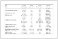


 下载:
下载:


 下载:
下载:

