College of Chemistry and Materials, Key Laboratory of Fluorine and Silicon for Energy Materials and Chemistry of Ministry of Education, Jiangxi Normal University, Nanchang 330022, China
* Corresponding authors. E-mail addresses: wusu.qin@163.com (S. Wu)
guiming@jxnu.edu.cn (G. Peng). 1 These authors contributed equally to this work.
Received Date:
18 January 2026 Accepted Date:
06 March 2026 Revised Date:
03 March 2026 Available Online:
15 December 2026
Abstract:
Photoelectrochemical cell (PEC) represents a sustainable technology that could convert solar energy into solar fuels. Synthesis of porous carbon nitride (CN) photoanode with large active surface is crucial for efficient PEC water splitting, however, remains challenging. This work reported a porous CN photoanode with large active surface enabled by melamine-urea comonomer film assembly followed with in-situ thermal condensation. It imparts large surface area, broadened light harvesting, facilitated charge separation, and significantly enhanced electrochemically active surface area. The as-synthesized CN photoanode delivered impressive PEC water splitting performance with photocurrent (at 1.23 V) up to 190 µA/cm2 in KOH solution, 2.2 times higher as that of compact CN photoanode. After addition of sacrificial agent in electrolyte, the photocurrent is boosted to 420 µA/cm2. Their IPCEs at 400 nm are 13% and 32%, respectively. The improved PEC activity was also visually evidenced by scanning electrochemical microscope measurement. The concept of comonomer film assembly-initiated porous CN film synthesis in this work provides a reliable approach to tailor the photophysical properties of in-situ synthesized CN film, which paves a pathway to enhance/broaden the applications of CN in electronic devices, not just limited to photoelectrochemical water splitting.
Photoelectrochemical cells (PECs) represent a renewable energy conversion technology that can convert solar energy into storable chemical fuels, such as hydrogen production through water-splitting, which offers a sustainable approach to alleviate the future energy tension [1-5]. Polymeric carbon nitride (CN), as a low-cost artificial semiconductor with appropriate bandgap for water splitting and many other reactions, has attracted enormous interest in energy/environment photocatalysis [6-10]. However, its application in PECs receives considerably less attention [4,11-17]. The key component in an efficient CN PEC device is the CN photoanode which requires sufficient light harvesting, sophisticated charge separation and electron transfer, and large active surface to enable fast reaction kinetics [12,15,18-24].
Unlike the easy modulation of CN powder material’s electronic properties via various tools such as cocatalyst engineering [25-29], doping [30-36], heterojunction construction [37-43], implementing these strategies in direct synthesis of CN photoanode usually sacrifices the CN/substrate adhesion due to the surface mismatch, leading to failure in synthesis of CN photoanode. To avoid hybridizing CN with other materials, monomer copolymerization usually results to uniform CN with tailored electronic properties and catalytic activity [44-47]. Previously, the monomer film assembling initiated CN photoanode synthesis has been validated as powerful methodology and showing successful applications in PEC water splitting [48-51]. While the chemical composition of the as-synthesized CN photoanode can be tuned by changing the composition of monomers. Among this methodology category, fabricating monomer film by doctor-blade coating technique is a general approach [11,12,48,52-54]. Its prerequisite is the formation of processible monomer paste with suitable viscosity [48,55]. As is known, most single monomer of CN suffers from difficulty in preparation of viscous paste with good coating ability, such as melamine. Improving the viscosity of the paste by formation of supramolecular or addition of reinforcement material (such as graphene oxide) could overcome the above problem [11,55]. Considering there could be specific interaction between different monomers in their mixture [48], rational combination of monomers could shift the rheology properties of their paste, thus holds possibility to fabricate comonomer film via doctor-blade coating and ultimately suitable for synthesis of CN photoanode by thermal condensation.
In addition, tuning the active site density and surface area of in-situ synthesized CN photoanode is another challenge but an urgent task for high PEC performance. Due to the challenges in synthesis of CN composite photoanode, many porosity engineering options for CN powders cannot be referred for synthesis of porous CN photoanode. Previously, incorporation of urea with melamine has been found good for synthesis more porous CN structure with N-vacancies (acting as electron trapping sites) which boosts the photocatalytic hydrogen production efficiency [56,57]. Therefore, it is expected that the comonomer film assembly strategy could simultaneously achieve in-situ synthesis of CN films meanwhile with tunable porosity and high active site density.
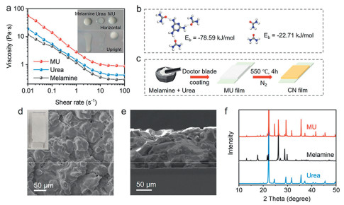
Herein, we reported the addition of urea into melamine paste significantly improved its casting ability which is good for doctor-blade coating to form a uniform comonomer film. After thermal polymerization, the obtained comonomer film is transformed into a porous CN photoanode with large active surface area. PEC water splitting investigation demonstrated impressive performance with photocurrent of 190 µA/cm2 in 0.1 mol/L KOH aqueous solution at 1.23 V upon 1 SUN illumination, which is 2.2-times higher than the melamine film derived CN photoanode. While in triethanolamine (TEOA)-contained KOH solution, the photocurrent reached 420 µA/cm2. Their IPCE values at 400 nm are up to 13% and 32%, respectively. The enhanced PEC performance is ascribed to the extended light absorption, facilitated charge separation and electron transfer, and high active surface area, thanks to the porous structure with defective surface. To search for processible monomer paste that could be doctor-blade coated onto a substrate prior to thermal condensation into CN photoanode, it was found that the mixture of melamine and urea (1:7) in ethylene glycol (EG) dramatically changes the rheology properties by increasing the viscosity of the paste (Fig. 1a), as well as visually evidenced by the reduced flowing ability (inset in Fig. 1a). The viscous melamine-urea (MU) paste remains stable without precipitation after 24 h-settling (Fig. S1 in Supporting information), while in contrast that melamine precipitates rapidly in EG (Fig. S1 in Supporting information) and urea shows too good solubility in EG to form film by coating (Figs. S2 and S3 in Supporting information). The molecular binding energy calculation proved the strong interaction between melamine and urea molecules (Eb = -78.59 kJ/mol) by preferentially forming three hydrogen bond connections around one melamine molecule (Fig. 1b), while the urea-urea interaction is much weaker (Eb = -22.71 kJ/mol). The well-constructed urea-melamine interconnection explains for the increased viscosity of MU paste. The increased viscosity of MU paste endows good casting processibility to form a unform MU film by doctor-blade coating (Figs. 1c and d). Scanning electronic microscopy (SEM) images witnessed the uniform merged morphology of MU film (Fig. 1d). Different from the particle morphology of melamine (Fig. S4 in Supporting information), the interstices between melamine particle are well filled with urea, ultimately forming a continuous MU composite layer on FTO (Fig. 1d). The thickness of the MU layer is ~125 µm (Fig. 1e). X-ray diffraction (XRD) pattern of the MU layer shows up the diffraction peaks of melamine and urea (Fig. 1f). The shifted intensities of XRD peaks when compared to the individual monomer indicate there is slight co-crystallization fashion because of the mutual interaction (Fig. 1f). Note that it is this mutual interaction changes the rheology properties of the MU paste and improves its casting ability. In consistence with XRD results, Fourier-transform infrared (FTIR) spectra of MU film showed combinative characteristic peaks of melamine and urea (Fig. S5 in Supporting information).
Figure 1
Figure 1.
(a) The relationship between viscosity and shear rate of melamine, urea, and MU pastes. Insets are photographs of melamine, urea, and MU pastes on horizontal and upright glass slides. (b) The molecular interaction configuration between melamine and urea, and their binding energies. (c) Schematic illustration of the synthesis of CN(mu) film. (d) Top-view SEM image of MU film. Inset is the photograph of MU film on FTO. (e) Cross-section SEM image of MU film. (f) XRD patterns of melamine, urea, and MU films.
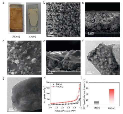
After thermal condensation of the MU film at 550 ℃ in N2 atmosphere for 4 h, uniform brown CN film (CN(mu)) with inherited MU film profile was obtained (Fig. 2a). Note that the thermal condensation of melamine film (Fig. S2 in Supporting information) resulted to an irregular shaped CN film (CN(m)) (Fig. 2a), probably because of the sublimation of melamine. The urea film cannot yield good CN film on FTO (Fig. S6 in Supporting information). These comparisons suggested the combination of melamine and urea into comonomer film could confine the synthesis of uniform CN film during thermal polymerization. Top-view SEM image of CN(mu) shows the open nanostructure arrays with their diameter of ~240 nm (Fig. 2b). The cross-section SEM shows the porous network structure within the CN(mu) film (Fig. 2c). The thickness is determined to be ~20 µm, significantly shrunk from the comonomer film because of the widely known monomer sublimation and the polycondensation process. EDS elemental mapping proved even distribution of C and N across the whole film (Fig. S7 in Supporting information), suggesting the formation of carbon nitride. Different from CN(mu), the CN(m) film has much compact structure with less porosity (Figs. 2d and e). The thickness of CN(m) film is ~30 µm (Fig. 2e). Note that due to the photoanode was illuminated from the backside (glass side) when performing PEC investigation, and the fact of limited light penetration depth and much smaller effective thickness (<< 20 µm) that allows electrons diffuse through without recombination [14], the thickness discrepancy between CN(mu) and CN(m) should have negligible contribution to their PEC performance difference. Transmission electron microscopy (TEM) image confirmed the highly holey structure of the CN(mu) nanostructure (Fig. 2f), different from the hole-free nanoflake structure of CN(m) (Fig. 2g) and wrinkled nanosheet obtained by calcination of urea powder (Fig. S8 in Supporting information). BET nitrogen adsorption-desorption isotherm tests demonstrated type-IV isotherms (Fig. 2h). In line with the porous and holey structure of CN(mu), the BET surface area of CN(mu) is 57.27 m2/g, almost four-folds higher as that of CN(m) (15.36 m2/g) (Fig. 2i). This porous and holey structure of CN(mu) with high surface area theoretically would benefit its photo/electrochemical application.
Figure 2
Figure 2.
(a) Photographs of CN(mu) and CN(m). (b) Top-view and (c) cross-section SEM images of CN(mu). (d) Top-view and (e) cross-section SEM images of CN(m). (f) TEM image of CN(mu). (g) TEM image of CN(m). (h) N2 adsorption–desorption isotherms of CN(m) and CN(mu). (i) BET surface area charts of CN(m) and CN(mu).
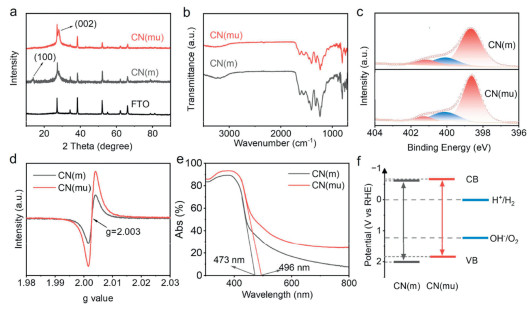
XRD characterizations showed the diffraction peak of (002) at 27° for both CN(mu) and CN(m) (Fig. 3a) [58]. The (100) diffraction peak at 13° appear in XRD pattern of CN(m) but did not show up for CN(mu) [59], implying the more disordered and defective in-plane structure led by copolymerization of melamine and urea. FTIR spectra demonstrated the stretching modes of C-N heterocycles between 1200 cm-1 and 1600 cm-1, while the breathing mode of the triazine units appears at about 810 cm-1 (Fig. 3b). The broad band in range of 3000-3400 cm-1 is indexed to the -NHx groups [60]. C 1s X-ray photoelectron spectroscopy (XPS) spectra demonstrate two main peaks at 284.8 and 288.2 eV, which are assigned to the C-C/C=C and C-N bonds (Fig. S9 in Supporting information), respectively. The N1s XPS spectrum of CN(mu) can be deconvoluted into three peaks at 398.8, 400.2, and 401.2 eV, assigned to C=N-C, N-C3, and C-NH-C/C-NH2 (Fig. 3c), respectively [61]. It is worthy to point out that the peak ratio of C=N-C/N-C3 for CN(mu) (3.66) is significantly lower than CN(m) (5.03) (Fig. 3c). This suggests the presence of N-vacancies in CN(mu), in agreement with its enhanced electron paramagnetic resonance (EPR) intensity (Fig. 3d). The structure disorder could be aroused by the different thermal polymerization rates and degrees of two different monomers (melamine and urea) during synthesis of CN(mu). In consistence with the dark brown color of CN(mu), it demonstrated improved UV-vis absorption with extended light absorption edge to 496 nm, while that for CN(m) is at 473 nm (Fig. 3e). Correspondingly, their bandgaps are 2.50 and 2.62 eV, respectively. Mott-Schottky measurements indicate their conduction band positions are at -0.61 and -0.66 eV for CN(m) and CN(mu) (Fig. S10 in Supporting information), respectively. Then the bandgap diagrams of both materials were obtained, which are found to straddle over the redox potential of water (Fig. 3f), highlighting their suitability for PEC water splitting.
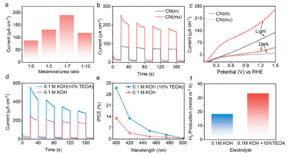
The photoelectrochemical (PEC) performance was evaluated in 0.1 mol/L KOH aqueous solution using a standard three-electrode system coupled with a solar simulator at the light intensity of 100 mW/cm2. It was found that CN(mu) photoanode derived from urea incorporated monomer film delivered significantly improved water oxidation photocurrent. Compared to the photocurrent of 87 µA/cm2 generated by CN(m), CN(mu) synthesized by thermal polymerization of MU film composed of melamine-urea comonomer film at the ratio of 1:5 generated photocurrent up to 130 µA/cm2 (Fig. 4a and Fig. S11 in Supporting information). Increasing the urea ratio to 1:7 maximized the PEC performance with photocurrent reaching 190 µA/cm2 (Figs. 4a and b, Fig. S11 in Supporting information). However, the photocurrent decreases when further introduce more urea (>7:1) into the monomer film (Fig. 4a), probably because of the too loose structure of the CN film which would deteriorate the charge separation and electron transfer (Fig. S12 in Supporting information). Linear sweeping voltammogram (LSV) curves under on/off 1-SUN illumination showed the low onset potential of 0.21 V vs. RHE for water splitting by the CN(mu) photoanode, lower than that of CN(m) (0.37 V) (Fig. 4c). Besides tested in 0.1 mol/L KOH, it delivered a photocurrent of 90 µA/cm2 in neutral 0.1 mol/L Na2SO4 solution. While in acidic solutions (0.5 mol/L H2SO4), the photocurrent reached an impressive value of 150 µA/cm2 (Fig. S13 in Supporting information). The observed photocurrent decay should be ascribed to the charge recombination because of the sluggish water oxidation kinetics since there is no cocatalyst used in this study. These all-pH PEC performance evaluations proved the good adaptability of the CN(mu) in various electrolytes. XRD and FTIR analysis confirmed the good chemical structure stability of CN(mu) after PEC test (Fig. S14 in Supporting information), while SEM observation proved the retained porous morphology (Fig. S15 in Supporting information).
Figure 4
Figure 4.
(a) The photocurrents of CN(mu) photoanodes synthesized using different mass ratios of melamine/urea as monomer. (b) The photocurrents of CN(m) and CN(mu) photoanodes under 1-SUN illumination. (c) LSV curves of CN(m) and CN(mu) under on/off 1-SUN illumination in 0.1 mol/L KOH aqueous solution. (d) Photocurrents, (e) IPCE at different wavelengths, and (f) H2 production of CN(mu) photoanode in 0.1 mol/L KOH aqueous solution with and without 10% TEOA.
Furthermore, in the presence of hole sacrificial agent of TEOA in 0.1 mol/L KOH solution, the photocurrent density was boosted to 420 µA/cm2 (Fig. 4d). Note that both the performances in KOH solution with and without TEOA by this porous CN photoanode are acceptable and comparative to other reported CN-based photoanodes (Fig. S16 and Table S1 in Supporting information). Taking the photocurrent ratio of that in 0.1 mol/L KOH solution to the one in presence of TEOA (IKOH/IKOH+TEOA) as the charge transfer efficiency, it is observed that the charge transfer efficiency of CN(mu) reached 45.2% (Fig. 4d), higher than CN(m)’s 42.6% (Fig. S17 in Supporting information), further validating the advantageous charge separation and excellent surface reaction efficiency of the porous CN(mu). The incident photon-to-current conversion efficiency (IPCE) measurements showed the onset wavelength of up to 480 nm (Fig. 4e), in consistence with the UV-vis absorption spectrum (Fig. 3e). Specifically, in 0.1 mol/L KOH aqueous solution, the IPCE at 400 nm is 13%. While after adding 10% TEOA, the IPCE is apparently improved with values of 32%, 13%, 5% at 400, 420, and 450 nm (Fig. 4e), respectively. All these values are higher than CN(m), with its IPCE of 12% and 6.6% at 400 nm in 0.1 mol/L KOH without and with presence of TEOA (Fig. S18 in Supporting information), respectively. Besides, since the efficiently separated photoelectrons are transported to the counter electrode, the generated higher value H2via proton reduction by photogenerated electrons at the counter electrode surface was tested by gas chromatography (GC). Quantitative analysis showed the H2 generation rate of 18.3 mmol m-2 h-1and 33.1 mmol m-2 h-1 in 0.1 mol/L KOH without and with addition of TEOA (Fig. 4f), respectively.
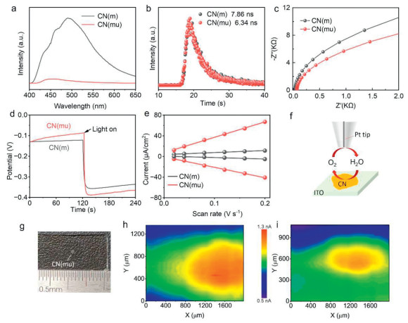
To better understand the improved PEC performance of CN(mu), the charge carrier dynamics were investigated. Photoluminescence (PL) spectra and its decay plots show that CN(mu) has lower PL intensity and shorter carrier lifetime than CN(m) (Figs. 5a and b) [62], suggesting the superior charge separation and electron transfer within CN(mu) probably because of more defects and exposed edges. This was further supported by electrochemical impedance spectroscopy (EIS) measurements which showed reduced charge transfer resistance (Rct) of CN(mu) (Fig. 5c) [63]. Furthermore, the open-circuit voltage (Voc) change upon on/off 1-SUN illumination was measured to evaluate the charge separation driving force developed across the photoanode [49,64]. Results showed that both CN(mu) and CN(m) responds immediately upon light illumination and established stable surface potential thereafter. CN(mu) has higher Voc change (0.29 V) than CN(m) (0.23 V) (Fig. 5d), indicating the improved charge separation ability within CN(mu). Electrochemically active surface area (ECSA) measurement demonstrates that CN(mu) has 7.4-times higher ECSA than CN(m) (Fig. 5e), which is in good accordance with its enhanced photoelectrochemical performance. The higher enhancement degree in ECSA (7.4-fold) than in BET surface area (3.73-fold) indicates the good PEC performance of CN(mu) is not just originated from the higher surface area but also from the more N-defective active sites. Moreover, scanning electrochemical microscope (SECM) test of CN(mu) on ITO glass in substrate-generation/tip collection mode demonstrated visually enhanced water oxidation current with respect to that of CN(m) (Figs. 5f-i), which strongly confirms the more active surface of CN(mu) towards water splitting.
Figure 5
Figure 5.
(a) PL spectra, (b) PL decay plots, (c) Nyquist plots tested at 1.23 V vs. RHE, (d) potential responses upon 1-SUN illumination in circuit condition, (e) cathodic and anodic charging currents at 0.1 V vs. Ag/AgCl of CN(mu) and CN(m) photoanodes. (f) Scheme of SECM test. (g) CN(mu) drop-cast on ITO glass for SECM test. (h) The current color contour image of CN(mu) and (i) the current color contour image of CN(m) at 1.85 V vs. RHE.
Correlating the material characterizations and electronic study, it can be concluded the excellent PEC performance of CN(mu) is a synergistical result of defective porous structure with high active surface area, extended light absorption, and improved charge separation.
In summary, to achieve efficient PEC water splitting by CN material, this work reported a porous CN photoanode with active surface derived from melamine-urea comonomer film. It was found that the addition of urea into the melamine paste (in ethylene glycol) improved its casting ability to form a uniform comonomer film. While after in-situ thermal polymerization, the obtained CN(mu) photoanode showed extended light absorption, favorable charge separation and electron transfer, and highly porous structure with large active surface. PEC investigations demonstrated improved water splitting performance with photocurrent of 190 µA/cm2 in 0.1 mol/L KOH aqueous solution at 1.23 V under 1 SUN illumination, 2.2 times higher as that of CN(m) derived from melamine layer. While in TEOA presented solution, the photocurrent is up to 420 µA/cm2. IPCE tests showed impressive values of 13% and 32% at 400 nm in KOH without and addition of TEOA, respectively. Overall, the melamine-urea comonomer polymerization strategy was innovatively implemented in direct growth of porous CN film on conducting substrate for PEC water splitting via comonomer film assembly, which enables favorable electronic properties modulation ranging from enhanced light harvesting, accelerated charge separation, and large active surface. The concept in this work is expected to pave a way for designing many other efficient CN-based electronic devices as well.
This work is supported by Natural Science Foundation of China (No. 22462012), Natural Science Foundation of Jiangxi for Distinguished Young Scholars (No. 20224ACB213003), Natural Science Foundation of Jiangxi (No. 20252BAC250026), “Double Thousand Plan” of Jiangxi province (No. jxsq2023101109), and Jiangxi Normal University.
Supplementary materials
Supplementary material associated with this article can be found, in the online version, at doi:10.1016/j.cclet.2026.112595.
Q. Ruan, M.K. Bayazit, V. Kiran, et al., Chem. Commun. 55 (2019) 7191-7194. doi: 10.1039/c9cc03084k
Figure 1
(a) The relationship between viscosity and shear rate of melamine, urea, and MU pastes. Insets are photographs of melamine, urea, and MU pastes on horizontal and upright glass slides. (b) The molecular interaction configuration between melamine and urea, and their binding energies. (c) Schematic illustration of the synthesis of CN(mu) film. (d) Top-view SEM image of MU film. Inset is the photograph of MU film on FTO. (e) Cross-section SEM image of MU film. (f) XRD patterns of melamine, urea, and MU films.
Figure 2
(a) Photographs of CN(mu) and CN(m). (b) Top-view and (c) cross-section SEM images of CN(mu). (d) Top-view and (e) cross-section SEM images of CN(m). (f) TEM image of CN(mu). (g) TEM image of CN(m). (h) N2 adsorption–desorption isotherms of CN(m) and CN(mu). (i) BET surface area charts of CN(m) and CN(mu).
Figure 4
(a) The photocurrents of CN(mu) photoanodes synthesized using different mass ratios of melamine/urea as monomer. (b) The photocurrents of CN(m) and CN(mu) photoanodes under 1-SUN illumination. (c) LSV curves of CN(m) and CN(mu) under on/off 1-SUN illumination in 0.1 mol/L KOH aqueous solution. (d) Photocurrents, (e) IPCE at different wavelengths, and (f) H2 production of CN(mu) photoanode in 0.1 mol/L KOH aqueous solution with and without 10% TEOA.
Figure 5
(a) PL spectra, (b) PL decay plots, (c) Nyquist plots tested at 1.23 V vs. RHE, (d) potential responses upon 1-SUN illumination in circuit condition, (e) cathodic and anodic charging currents at 0.1 V vs. Ag/AgCl of CN(mu) and CN(m) photoanodes. (f) Scheme of SECM test. (g) CN(mu) drop-cast on ITO glass for SECM test. (h) The current color contour image of CN(mu) and (i) the current color contour image of CN(m) at 1.85 V vs. RHE.


 DownLoad:

 下载:


 下载:

