Citation:
Feng Xu, Ziqi Ning, Donghua Zhang, Chunlong Dai, Qinxue Wen, Fengxia Deng, Bo Lai, Zhiqiang Chen. Mechanism and pathway for the electrocatalytic degradation of an organic phosphine scale inhibitor by a novel Ti/IrO2-RuO2(Bi+[Emim]BF4) electrode[J]. Chinese Chemical Letters,
2026, 37(10): 112435.
doi:
10.1016/j.cclet.2026.112435
Mechanism and pathway for the electrocatalytic degradation of an organic phosphine scale inhibitor by a novel Ti/IrO2-RuO2(Bi+[Emim]BF4) electrode
English
Mechanism and pathway for the electrocatalytic degradation of an organic phosphine scale inhibitor by a novel Ti/IrO2-RuO2(Bi+[Emim]BF4) electrode
Received Date:
17 September 2025 Accepted Date:
19 January 2026 Revised Date:
23 November 2025 Available Online:
15 October 2026
Abstract:
Organic phosphine scale inhibitors are widely used chemical additives in industrial water treatment. Due to its high stability, high solubility and anti-biodegradability, it can persist in water bodies for a long time and is a potential long-term source of phosphorus pollution. This study developed a novel Ti/IrO2–RuO2 electrode co-modified with bismuth and ionic liquid [Emim]BF4via thermal decomposition for electrocatalytic degradation of hydroxyethylene-1,1-diphosphate (HEDP) in reverse osmosis concentrate (ROC). Analyses with scanning electron microscopy (SEM), energy-dispersive spectroscopy (EDS), X-ray diffraction (XRD) revealed that adding (Bi+[Emim]BF4) to the electrode reduced the crystal grain size by 33%, enhancing compactness while maintained the typical oxide crystals rutile crystal structure. Electrochemical tests demonstrated that the Ti/IrO2-RuO2(Bi+[Emim]BF4) electrode significantly outperformed its Ti/IrO2-RuO2 counterpart and had a lifespan 1.2 times longer. Then, at optimal conditions, current density of 30 mA/cm2, initial pH of 3, 0.25 mol/L NaCl electrolyte, and a reaction time of 120 min, the removal of HEDP reached 84.22%. Mechanistic studies indicated that indirect oxidation by active chlorine dominated. Ultimately, the Ti/IrO2-RuO2(Bi+[Emim]BF4) electrode system removed 82.77% of HEDP, 83.16% of COD, and 49.73% of UV254 from actual ROC within 60 min, albeit with a limited TOC removal rate of 30.23%. Notably, it achieved a 91.55% removal rate for fluorescent substances within 10 min. This research provides valuable insights for enhancing the performance of iridium-ruthenium electrode and designing efficient electrocatalytic oxidation systems for treating phosphorus-containing wastewater.
Hydroxyethylene-1,1-diphosphate (HEDP) is a widely used and cost-effective organic phosphonate scale inhibitor, employed in industrial circulating cooling water, reverse osmosis systems, and oilfield reinjection water [1–5]. Despite its good scale inhibition properties, HEDP is highly stable, resistant to hydrolysis, and biologically toxic [5,6]. The direct discharge of reverse osmosis concentrate (ROC) containing HEDP can elevate phosphorus levels in water bodies, potentially causing eutrophication [7]. Conventional methods such as biological oxidation, adsorption, and coagulation are often ineffective at removing HEDP [5,8–13]. Thus, developing an efficient treatment for HEDP is crucial to mitigate environmental risks and enhance wastewater management.
Electrochemical advanced oxidation processes (EAOPs) are a promising technology for industrial wastewater treatment, using electrons as the primary reagent without chemical additives [14]. Among EAOPs, anodic oxidation (AO) is the simplest method, where efficiency depends on pollutant mass transfer to the anode surface [15]. The ions in the ROC with high salinity act as natural electrolytes, which can enhance the electrical conductivity of the AO system and promote the degradation of pollutants HEDP [16]. Since anode performance dictates active species generation and oxidation efficiency [17], developing stable, high-performance anodes is crucial for electrochemical treatment of high-salinity phosphorus-containing wastewater.
Currently, common anode materials in AO technology include Pt, boron-doped diamond (BDD), dimensionally stable anodes (DSA), and graphite. Among these, DSA electrodes stand out due to their cost-effectiveness and simple preparation, making them a focus in wastewater treatment research [18,19]. For instance, a Ti/IrO2+MnO2+CeO2 composite DSA anode demonstrated superior electrocatalytic performance over graphite in terms of cell voltage, current efficiency, and energy consumption [20]. Imidazolium ionic liquids are a class of molten salts composed entirely of ions that remain liquid at relatively low temperatures. Known for their easy synthesis, excellent stability, good conductivity, and wide electrochemical window, they have gained increasing attention in electrochemical applications. Researchers have enhanced PbO2 electrodes by incorporating these ionic liquids into electrodeposition solutions, with [Emim]BF4-modified electrodes showing higher electrocatalytic activity [21,22]. Additionally, doping electrode coatings with metals like Bi, Ce, or Ni can further improve oxygen evolution potential (OEP) and electron transfer, boosting electrocatalytic performance [23,24].
This study modified the active layer of iridium-ruthenium electrodes by doping ionic liquid [Emim]BF4 and bismuth nitrate catalyst to enhance their electrocatalytic activity and service life in the AO process. With HEDP as the target pollutant, the optimal modified electrode was first selected based on electrode characterization, electrochemical performance, stability tests, and degradation efficiency. Subsequently, the effects of current density, initial pH, and reaction time on the HEDP removal rate were investigated using a single-factor approach, and the degradation mechanisms and pathways were explored. Finally, the performance of the modified electrode was evaluated for treating high-salinity ROC. The findings provide new insights into enhancing the performance of iridium-ruthenium electrodes and designing efficient electrocatalysts, contributing to water environmental protection and sustainable resource utilization.
The experimental reaction device was described in Fig. S1 (Supporting information). Modified electrodes with varying amounts of ionic liquid [Emim]BF4 were prepared by adding 0, 2.5, 5, 7.5, and 10 µL to the coating solution. The influence of different amounts of ionic liquid on the degradation effect of HEDP was analyzed in Supporting information. As can be seen from Fig. S2 (Supporting information), the optimal addition dosage of [Emim]BF4 was 5 µL, which was the volume ratio to n-butanol of 1:2760.
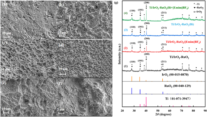
Fig. 1a is the morphology diagram of pure titanium. A comparison between Figs. 1b–e and the titanium substrate morphology in Fig. 1a indicates that no titanium base was exposed on the surfaces of the four iridium-ruthenium electrodes. Fig. 1b shows the typical thermal decomposition cracking structure of the iridium-ruthenium electrode. At this stage, the coating exhibited a relatively loose structure, allowing gases generated during electrochemical reactions to accumulate stress on both sides of cracks, ultimately causing coating delamination. Consequently, this structural characteristic could potentially accelerate electrode failure [25]. In contrast, Fig. 1e demonstrates that the [Emim]BF4 and Bi co-doped electrode possessed smaller crystalline particles with a more compact arrangement. This denser microstructure more effectively shielded the substrate from corrosive media, thereby significantly improving the corrosion resistance of the titanium base material [26].
Figure 1
Figure 1.
(a) SEM of Ti (1 K). (b) SEM of Ti/IrO2-RuO2 (1 K). (c) SEM of Ti/IrO2-RuO2([Emim]BF4) (1 K). (d) SEM of Ti/IrO2-RuO2 (Bi) (1 K). (e) SEM of Ti/IrO2-RuO2(Bi+[Emim]BF4) (1 K). (f) SEM of Ti/IrO2-RuO2(Bi+[Emim]BF4) (5 K). (g) XRD pattern of iridium ruthenium electrode.
As shown in Fig. 1f, the SEM image of the Ti/IrO2-RuO2(Bi+[Emim]BF4) electrode at 5000 times magnification reveals that the coating consisted of spherical, cookie-like particles stacked on top of each other without visible cracks. The enhanced surface roughness and improved coating-substrate interfacial bonding significantly increase the electrode’s mechanical stability, effectively preventing coating delamination and extending its service life. Furthermore, this unique microstructure with its spherical particle stacking creates a larger electrochemical active surface area compared to conventional flat electrodes, providing more active sites and consequently enhancing the electrode’s catalytic activity.
The EDS analysis depicted in Fig. S3 (Supporting information) clearly presents the presence of the corresponding Ir and Ru spectral peaks in both the Ti/IrO2-RuO2(Bi) and Ti/IrO2-RuO2(Bi+[Emim]BF4) electrodes. This confirms that the main constituents of the iridium-ruthenium electrodes’ active layer had been successfully integrated into the electrode coatings. As shown in Fig. S3, the total atomic percentages of Ir and Ru on the surface of the Ti/IrO2-RuO2(Bi) electrode was 19.53%, whereas on the surface of the Ti/IrO2-RuO2(Bi+[Emim]BF4) electrode, this value was elevated to 25.69%. It manifests that the inclusion of the ionic liquid [Emim]BF4 significantly enhanced the formation of the iridium-ruthenium active layer. The Bi peak in Fig. S3 was faint due to its low concentration, below the detection limit. Inductively Coupled Plasma Optical Emission Spectrometer (ICP-OES) analysis confirmed successful Bi doping in the coatings, with contents of 2312.13 mg/kg in Ti/IrO2-RuO2(Bi) and 4168.01 mg/kg in Ti/IrO2-RuO2(Bi+[Emim]BF4). The experimental results indicate that the ionic liquid [Emim]BF4 effectively promoted Bi incorporation within the active coating. As observed in Fig. 1g, XRD patterns of the four electrodes exhibited 10 distinct diffraction peaks at identical 2θ values, confirming that [Emim]BF4 and Bi doping did not change the rutile crystal structure. The peaks matched IrO2 (110, 101, 200, 211) and RuO2 (110, 101, 200, 211), but slight shifts occurred compared to standard PDF cards (#40-1290 for RuO2, #15-0870 for IrO2). These shifts suggest lattice distortion from Ru4+, Ir4+, and Bi3+ substitution, forming a stable trimetallic oxide solid solution during electrolysis [27].
By employing MDI Jade XRD analysis software and applying the Scherrer formula [28], we calculated that the grain size of the Ti/IrO2-RuO2(Bi+[Emim]BF4) coating was 42.7 nm, which was significantly smaller than that of unmodified the Ti/IrO2-RuO2 electrode (63.2 nm). This reduction in grain size indicates that the co-doped modified electrode possesses a finer microstructure. Notably, smaller crystallites on the electrode surface contribute to a larger specific surface area and a more compact structure, thereby increasing the number of active sites and ultimately enhancing the electrode’s catalytic performance [29]. What is more, as shown in Fig. 1g, the diffraction peak of the Ti/IrO2-RuO2(Bi+[Emim]BF4) electrode coating was sharper and more intense than that of the unmodified electrode, while the diffraction peak corresponding to the Ti substrate was significantly weakened. These findings prove the increased activity of the co-doped iridium ruthenium electrode and suggest that its coating was compact and resistant to detachment. However, no diffraction peaks corresponding to crystalline phases such as Bi2O3 were detected in the XRD pattern. This absence may be attributed to the low doping concentration of Bi in the electrode coating, which falls below the detection limit of the instrument—a conclusion consistent with the EDS analysis results.
The better the chlorine evolution performance of an electrode, the more free chlorine it produces, and the higher its oxidation efficiency [30]. Obviously, an anode with a lower chlorine evolution potential favors active chlorine formation, thereby enhancing its electrocatalytic oxidation capacity for pollutant degradation. Hence, an anode with a lower chlorine evolution potential exhibits higher active chlorine generation, resulting in enhanced electrocatalytic oxidation efficiency for pollutant removal.
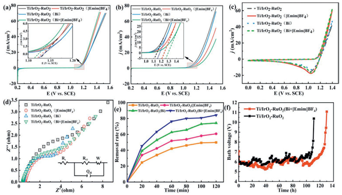
In Fig. 2a, the Ti/IrO2-RuO2(Bi+[Emim]BF4) electrode displayed the lowest chlorine evolution potential, exerting superior chlorine evolution performance. This enhancement originated from the co-doping of Bi and [Emim]BF4, which significantly improved the electrocatalytic activity of the Ti/IrO2-RuO2 electrode. Nevertheless, during electrocatalytic oxidation, the oxygen evolution reaction (OER) at the anode competes with pollutant degradation, accordingly reducing current efficiency. Furthermore, gas evolution may induce coating defects such as pores and cracks, potentially accelerating electrode coating degradation [31]. Noticeably, the higher OEP more effectively suppresses OER, consequently enhancing catalytic pollutant oxidation [32]. As shown in Fig. 2b, the Ti/IrO2-RuO2(Bi+[Emim]BF4) electrode presented the highest OEP among all modified electrodes. This result clearly indicate that the incorporation of Bi and [Emim]BF4 effectively inhibited OER [33].
Figure 2
Figure 2.
Properties of iridium-ruthenium-titanium electrodes. (a) Chlorine evolution curve. (b) Oxygen evolution curve. (c) Cyclic voltammetry (CV) curve. (d) Electrochemical impedance spectroscopy (EIS) curve. (e) Oxidation performance test. (f) Acceleration life test. Reaction condition (a-d): Ti/IrO2-RuO2, Ti/IrO2-RuO2([Emim]BF4), Ti/IrO2-RuO2(Bi), Ti/IrO2-RuO2(Bi+[Emim]BF4) electrodes were used as working electrodes, platinum plates were used as auxiliary electrodes, and Ag/AgCl electrodes were used as reference electrodes. Reaction condition (e): [HEDP] = 50 mg/L, electrolyte: [NaCl] = 0.25 mol/L, current density = 30 mA/cm2. Reaction condition (f): electrolyte: [H2SO4] = 1 mol/L, current density = 1 A/cm2.
Fig. 2c shows that the four electrodes exhibited similar cyclic voltammetric (CV) profiles, suggesting comparable electrochemical characteristics. The current densities followed this order: Ti/IrO2-RuO2([Emim]BF4) (17.61 mA/cm2) > Ti/IrO2-RuO2(Bi+[Emim]BF4) (17.11 mA/cm2) > Ti/IrO2-RuO2 (15.66 mA/cm2) > Ti/IrO2-RuO2(Bi) (12.97 mA/cm2). This trend clearly confirms that [Emim]BF4 doping substantially enhanced the current response [33]. Especially, the [Emim]BF4-modified electrodes showed significantly larger CV curve areas compared to the undoped and Bi-only doped electrodes. These findings indicate that [Emim]BF4 incorporation not only improved electrode activity but also increased capacitance, accordingly facilitating electrocatalytic oxidation reactions [33].
Electrochemical impedance spectroscopy (EIS) was employed to investigate the charge transfer characteristics of electrodes with different doping compositions. Generally, a smaller arc diameter corresponds to lower charge transfer resistance, which consequently indicates more facile electrochemical reactions and reduced energy consumption [34]. Fig. 2d, the Nyquist plot exposed distinct differences among the electrodes. The unmodified Ti/IrO2-RuO2 electrode exhibited the largest arc diameter, in contrast, all modified electrodes showed varying degrees of diameter reduction. Obviously, the Ti/IrO2-RuO2(Bi+[Emim]BF4) co-doped electrode demonstrated the smallest arc diameter. As a consequence, the co-doped electrode possessed lower electrochemical reaction resistance, a more rapid interfacial charge transfer rate, and superior electrochemical catalytic performance [35].
HEDP was chosen as the target pollutant with an initial concentration of 50 mg/L to evaluate the electrode electrocatalytic performance. As shown in Fig. 2e, the HEDP removal efficiency increased progressively with reaction time during the electrocatalytic oxidation process. After 120 min of treatment, the Ti/IrO2-RuO2(Bi+[Emim]BF4) co-doped electrode certified superior performance with 84.22% removal efficiency, representing a 35.37% improvement over the unmodified Ti/IrO2-RuO2 electrode (49.85%). While, the removal efficiencies of Ti/IrO2-RuO2([Emim]BF4) and Ti/IrO2-RuO2(Bi) electrodes were 60.74% and 74.29%, respectively. In addition, the bismuth-only doped electrode showed 13.55% higher efficiency than the [Emim]BF4-doped counterpart, attributable to the enhanced catalytic activity of ternary metal oxide crystals formed in the bismuth-modified electrode coating.
To assess electrode stability, accelerated lifetime tests were conducted under standardized conditions [32]. As illustrated in Fig. 2f, both electrode initially sustained a stable cell potential of approximately 6 V. Noteworthily, the Ti/IrO2-RuO2 electrode experienced a significant potential increase after 111 h of continuous operation, while the Ti/IrO2-RuO2(Bi+[Emim]BF4) electrode exhibited increased significantly after continuous operation for 130 h. These experimental results directly reflect the accelerated lifetime characteristics of the electrodes [36]. Based on the empirical correlation between the actual lifetime and the accelerated lifetime established by Correa-Lozano et al. [37], it was estimated that the service life of the Ti/IrO2-RuO2(Bi+[Emim]BF4) electrode could reach 13,000 h (542 d), which was 1.2 times that of the unmodified electrode. As a consequence, the enhanced stability can be attributed to the improved mechanical integrity and electrochemical stability of the electrode coating through Bi and [Emim]BF4 co-doping [38]. This is consistent with the SEM characterization results, namely that the Ti/IrO2-RuO2(Bi+[Emim]BF4) electrode has a refined microstructure, reduced grain size and dense surface morphology, which helps to improve its stability.
The incorporation of Bi and [Emim]BF4 significantly extended the service life of Ti/IrO2-RuO2 electrodes. The optimized Ti/IrO2-RuO2(Bi+[Emim]BF4) electrode demonstrated superior performance in three aspects: (1) enhanced electrochemical activity, (2) improved electrocatalytic oxidation capacity, and (3) exceptional stability. These superior properties make it a promising anode material for wastewater treatment applications. Therefore, the Ti/IrO2-RuO2(Bi+[Emim]BF4) electrode was selected for further experimental investigations.
The device utilized in electrocatalytic oxidation degradation experiment was shown in Fig. S4 (Supporting information). The effects of current density, initial pH and reaction time on the degradation of HEDP within the electrocatalytic system were studied and shown in Figs. S5–S7 (Supporting information). Under conditions where HEDP concentration was 50 mg/L and NaCl electrolyte concentration was 0.25 mol/L, the removal efficiency, reaction kinetics, energy consumption, and temperature of the catalytic system were analyzed under varying reaction conditions. Comprehensive analysis demonstrated that the system achieved minimal energy consumption and maximum MIT degradation efficiency at 30 mA/cm2 current density, pH 3, and 120 min. Subsequent experiments were conducted under these optimal conditions.
Electrocatalytic oxidation of organics proceeds through two pathways: Direct oxidation via anode electron transfer and indirect oxidation involving electrogenerated oxidants like •OH or active chlorine.
Direct oxidation primarily relies on electron transfer from pollutants to the anode to degrade pollutants in the electrocatalytic system (Eq. 1) [39]. Initially, pollutants migrate from the bulk solution and adsorb onto the anode surface. Subsequently, electron transfer from the adsorbed pollutants to the anode occurs, leading to the oxidation of pollutants on the anode surface.
where R is a targeted contaminant, M is an active site on the anode surface.
To elucidate the degradation mechanism of HEDP in the electrocatalytic system, sodium sulfate was employed as the electrolyte to eliminate interference from active chlorine species. The electrolyte concentrations were carefully controlled to ensure equal charge transfer across all experiments. Since methanol (MeOH) can effectively quench hydroxyl radicals (•OH) and sulfate radicals (SO4•‒), its addition effectively suppresses the indirect oxidation pathway [40]. Therefore, under these experimental conditions, the degradation of HEDP can be entirely attributed to direct electron transfer at the electrode surface.
As depicted in Fig. S8a (Supporting information), after adding MeOH, the removal rate of HEDP was 22.88% by electrocatalytic oxidation for 120 min. This value represents the contribution of direct electron transfer at the electrode surface. At the same time, the removal rate further confirms sustained electrode activity throughout the reaction period. Fig. S8b (Supporting information) displays that the rate constant decreased to 0.00221 min-1 with MeOH addition, corresponding to an 87.11% reduction compared to the system without MeOH. The results demonstrate that radical-mediated pathways account for 87.11% of the total degradation efficiency.
Indirect oxidation is a process where pollutants are degraded by reactive species generated within the electrocatalytic system.
The electrochemical oxidation of water at the electrode surface generates hydroxyl radicals (•OH) (Eq. 2) [41]. These radicals subsequently adsorb onto the anode surface, enabling indirect oxidation of target contaminants (Eq. 3) [42]. And yet, the competing OER (Eq. 4) reduces the oxidation efficiency by consuming available reactive sites [43]. Consequently, electrode material properties significantly influence the indirect oxidation mechanism through their effects on both •OH generation and OER competition.
Tert-butanol (TBA) serves as an efficient •OH quenching agent due to its strong radical scavenging capability [44]. By comparing HEDP removal efficiency with and without TBA addition (Fig. S8c in Supporting information), the contribution of •OH was evaluated quantitatively to the oxidation process [45]. The removal rate decreased from 82.18% to 66.86% after 120 min upon TBA addition, revealing a 15.32% contribution from •OH-mediated oxidation. Although HEDP degradation still followed pseudo-first-order kinetics with TBA addition (Fig. S8d), the rate constant decreased by 38.83% (to 0.01049 min-1), indicating that •OH was involved in the oxidative decomposition.
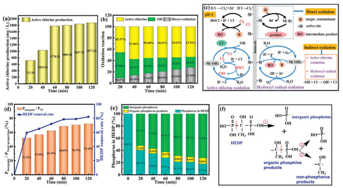
Chloride ions were electrochemically oxidized to active chlorine species at the anode surface, exhibiting strong oxidative capacity for HEDP degradation. As depicted in Fig. 3a, the Ti/IrO2-RuO2(Bi+[Emim]BF4) electrode generated 1877.23 mg/L active chlorine after 120 min of electrocatalysis, a 25-fold increase compared to the Ti/RuO2-IrO2-TiO2 electrode [46]. This significant difference highlights the critical influence of electrode composition on active chlorine generation efficiency.
Figure 3
Figure 3.
(a) Active chlorine production during electrocatalytic oxidation. (b) Contribution ratio of different oxidation modes in electrocatalytic reaction process. (c) Diagram of degradation mechanism of target pollutants in electrocatalytic system. (d) HEDP removal rate and inorganic phosphorus proportion in total phosphorus during electrocatalytic oxidation. (e) Phosphorus content proportion of each component during electrocatalytic oxidatio. (f) HEDP electrocatalytic oxidation degradation transformation pathway.
However, the speciation of active chlorine depends critically on solution pH. The dominant forms include Cl2 (pH ≤ 3), HClO (3 < pH < 8), and ClO- (pH > 8) [14]. Since HClO and Cl2 possess higher redox potentials than ClO−, the oxidation of HEDP must be faster in an acidic media than in an alkaline media [14,47]. In this electrocatalytic oxidation system (initial pH 3), the following electrochemical reactions occurred on the anode (Eqs. 5–8) [48–50].
The Ti/IrO2-RuO2(Bi+[Emim]BF4) electrode appeared a low chlorine evolution potential (E0 = 1.107 V vs. SHE), promoting active chlorine generation through Eq. 5. But, the active chlorine production rate progressively declined during the reaction. This decrease resulted from accelerated active chlorine decomposition and volatilization at elevated temperatures, which eventually exceeded the generation rate.
As shown in Fig. 3b, under optimal operating conditions of Ti/IrO2-RuO2(Bi+[Emim]BF4) electrode electrocatalytic system, indirect oxidation played a major role in the catalytic oxidation of HEDP, in which active chlorine species contributed the most in the degradation of HEDP. Direct oxidation showed steady growth with reaction time, while •OH concentration gradually decreased due to its consumption through reaction with Cl− to form active chlorine radicals (Eq. 9). The active chlorine-mediated oxidation exhibited rapid initial growth, followed by progressive deceleration and eventual slight decline. At pH < 3.3, Cl2 formation and subsequent volatilization from the reactor reduced active species utilization (Eq. 8). The pollutant degradation mechanism is comprehensively illustrated in Fig. 3c.
Fig. 3d demonstrates that the removal rate of HEDP after 120 min reaction was 82.18%, while the concentration of inorganic phosphorus represented 72.40% of the total phosphorus concentration. The results confirm cleavage of the C-P bond in HEDP through electrocatalytic oxidation, leading to phosphonyl group removal and inorganic phosphorus formation. During HEDP electrocatalytic oxidation, phosphorus species were emerged among three forms: (ⅰ) Residual HEDP, (ⅱ) organic phosphorus intermediates, and (ⅲ) inorganic phosphorus products. The dynamic evolution of these phosphorus components is quantitatively shown in Fig. 3e. The proposed degradation pathway (Fig. 3f) involves two consecutive reactions. Primary oxidation (Reaction ①), cleavage of one C-P bond in HEDP generates organic phosphorus intermediates and inorganic phosphate. Secondary oxidation (Reaction ②), further breakdown of intermediates through additional C-P bond cleavage yields inorganic phosphate and non-phosphorus end products.
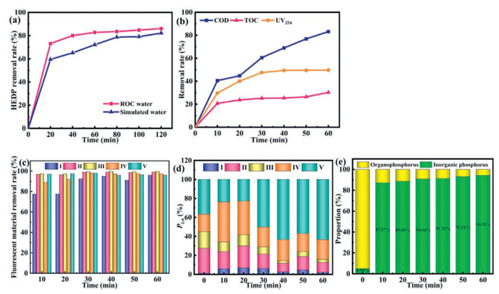
As shown in Fig. 4a, the process verified high efficiency in removing HEDP from ROC, achieving a removal rate of 82.77% after 60 min and further increasing to 86.09% after 120 min. In contrast, under identical conditions, the simulated water system achieved only an 82.18% HEDP removal rate after 120 min. Noticeably, the actual ROC system consistently manifested superior removal efficiency compared to the simulated water system. It is attributed to the conductivity in the ROC medium being as high as 84.4 µS/cm (Table S1 in Supporting information). These ions improve the conductivity of the system, therefore accelerating the electrocatalytic oxidation reaction. Based on these results, a reaction time of 60 min was selected for subsequent experiments in actual ROC.
Figure 4
Figure 4.
(a) Removal rate of HEDP electrocatalytic oxidation in real ROC. (b) The removal rate of COD, TOC and UV254 during electrocatalytic oxidation of actual ROC. (c) The removal rate of fluorescent substances in electrocatalytic oxidation of actual ROC. (d) The proportion of the contents of fluorescent substances in the electrocatalytic oxidation of the actual ROC. (e) The proportion of the contents phosphorus in the electrocatalytic oxidation of the actual ROC. Reaction condition (a-e): [HEDP] = 50 mg/L, electrolyte [NaCl] = 0.25 mol/L, current density = 30 mA/cm2, pH 3, 60 min. Ⅰ-Ⅴ: representing tyrosine aromatic proteins (Ⅰ), tryptophan aromatic proteins (Ⅱ), fulvic acid organic compounds (Ⅲ), dissolved microbial metabolites (Ⅳ) and humic acids (Ⅴ), respectively.
The electrocatalytic system has achieved the decrement of organic matter in ROC, as shown in Fig. 4b, COD levels decreased from 760 mg/L to 128 mg/L (83.16% removal). Simultaneously, TOC reduction reached 30.23% (239 mg/L to 166.75 mg/L). The results certify that the Ti/IrO2-RuO2(Bi+[Emim]BF4) electrode exhibits strong oxidative capability for organic matter, though with limited mineralization efficiency. Besides, the 49.73% reduction in UV254 absorbance (9.21 cm-1 to 4.63 cm-1) suggests effective degradation of unsaturated organic compounds in this electrocatalytic system.
Three-dimensional excitation-emission matrix (EEM) fluorescence spectroscopy analysis revealed the composition and transformation of fluorescent organic matter in ROC. The EEM spectra were categorized into five distinct regions (Ⅰ-Ⅴ) corresponding to specific organic components: tyrosine aromatic proteins (Ⅰ), tryptophan aromatic proteins (Ⅱ), fulvic acid organic compounds (Ⅲ), dissolved microbial metabolites (Ⅳ) and humic acids (Ⅴ), respectively in Fig. 4c. During the initial 10 min of electrocatalytic oxidation, the fluorescence intensity of the fluorescent substances decreased rapidly, followed by a gradual slowdown and stabilization of the decline rate. This degradation pattern illustrates the superior removal efficiency of the Ti/IrO2-RuO2(Bi+[Emim]BF4) electrode system, achieving 97.74% overall elimination of fluorescent substances within 60 min. Moreover, differential removal efficiencies were observed among specific components. Tryptophan aromatic proteins (Ⅱ) and fulvic acid compounds (Ⅲ) displayed exceptional removal rates exceeding 99%, while humic acids (Ⅴ) demonstrated 96.1% elimination. Comparatively, tyrosine aromatic proteins (Ⅰ) and dissolved microbial metabolites (Ⅳ) showed slightly lower but still substantial removal efficiencies of 96.05% and 97.41%, respectively.
From Fig. 4d, in the untreated ROC, the fluorescence intensities of regions Ⅰ-Ⅴ accounted for 1.26%, 26.24%, 17.57%, 18.25% and 36.67% of the total fluorescence intensity, respectively. This suggests that humic acids (Ⅴ) constituted the largest proportion of the fluorescent substances in the actual ROC. As electrocatalytic oxidation progressed, tryptophan aromatic proteins (Ⅱ) and fulvic acid organic compounds (Ⅲ) were effectively removed. However, tyrosine-type aromatic proteins (Ⅰ), dissolved microbial metabolites (IV) and humic acids (Ⅴ) all exhibited an accumulation of intermediate products resulting from the conversion of substance. Particularly, the conversion to humic acids (Ⅴ) increased to 26.73%, raising the proportion of humic acids (Ⅴ) in the system as high as 63.40%.
Fig. 4e shows that inorganic phosphorus accounted for merely 4.90% of total phosphorus in untreated ROC. As electrocatalytic oxidation progressed, inorganic phosphorus concentration increased progressively, as well as organophosphorus levels declined correspondingly. At the end of the reaction, the concentration of inorganic phosphorus accounted for 94.34% of total phosphorus. These results confirm that the electrocatalytic oxidation efficiently transforms organic phosphorus into inorganic species in real ROC.
In summary, this study successfully fabricated a Ti/IrO2-RuO2(Bi+[Emim]BF4) electrode through synergistic modification with the ionic liquid [Emim]BF4 and bismuth nitrate. Compared to conventional Ti/IrO2-RuO2 electrodes, the electrode exhibits superior electrochemical performance, enhanced catalytic oxidation efficiency, and prolonged service lifetime. Through a predominant active chlorine-mediated indirect oxidation mechanism, the system achieved 86.09% HEDP removal efficiency in ROC. To speak of, the electrocatalytic system enabled targeted cleavage of C-P bonds, realizing 94.34% conversion of organophosphates to inorganic phosphorus. These findings provide a theoretical basis for the treatment strategies of phosphorus-containing wastewater in a high-salt environment.
The authors declare that they have no known competing financial interests or personal relationships that could have appeared to influence the work reported in this paper.
Acknowledgments
This study is funded by the National Natural Science Foundation of China (No. U25A20365), the National Key Research and Development Program of China (No. 2023YFC3905603), the Key R&D Program of Heilongjiang Province (No. 2024ZX03C04) and the National Engineering Research Center for Sludge Safe Disposal (No. Z2024A002).
Supplementary materials
Supplementary material associated with this article can be found, in the online version, at doi:10.1016/j.cclet.2026.112435.
[1]
H.J. Lee, M.A. Halali, T. Baker, S. Sarathy, C.F. de Lannoy, Sep. Purif. Technol. 240 (2020) 116549. doi: 10.1016/j.seppur.2020.116549
[2]
C. Li, Q.F. Yang, D.K. Liu, H.F. Nie, Y.Q. Liu, J. Environ. Chem. Eng. 9 (6) (2021) 106895. doi: 10.1016/j.jece.2021.106895
[3]
C. Li, Q. Yang, S. Lu, Y. Liu, J. Inorg. Mater. 36 (2021) 841–846. doi: 10.15541/jim20200512
[4]
X.A.M. Mutke, K. Tavichaiyuth, F. Drees, H.V. Lutze, T.C. Schmidt, Water Res. 233 (2023) 119571. doi: 10.1016/j.watres.2023.119571
[5]
R. Ketrane, B. Saidani, O. Gil, L. Leleyter, F. Baraud, Desalination 249 (2009) 1397–1404. doi: 10.1016/j.desal.2009.06.013
Figure 1
(a) SEM of Ti (1 K). (b) SEM of Ti/IrO2-RuO2 (1 K). (c) SEM of Ti/IrO2-RuO2([Emim]BF4) (1 K). (d) SEM of Ti/IrO2-RuO2 (Bi) (1 K). (e) SEM of Ti/IrO2-RuO2(Bi+[Emim]BF4) (1 K). (f) SEM of Ti/IrO2-RuO2(Bi+[Emim]BF4) (5 K). (g) XRD pattern of iridium ruthenium electrode.
Figure 3
(a) Active chlorine production during electrocatalytic oxidation. (b) Contribution ratio of different oxidation modes in electrocatalytic reaction process. (c) Diagram of degradation mechanism of target pollutants in electrocatalytic system. (d) HEDP removal rate and inorganic phosphorus proportion in total phosphorus during electrocatalytic oxidation. (e) Phosphorus content proportion of each component during electrocatalytic oxidatio. (f) HEDP electrocatalytic oxidation degradation transformation pathway.
Figure 4
(a) Removal rate of HEDP electrocatalytic oxidation in real ROC. (b) The removal rate of COD, TOC and UV254 during electrocatalytic oxidation of actual ROC. (c) The removal rate of fluorescent substances in electrocatalytic oxidation of actual ROC. (d) The proportion of the contents of fluorescent substances in the electrocatalytic oxidation of the actual ROC. (e) The proportion of the contents phosphorus in the electrocatalytic oxidation of the actual ROC. Reaction condition (a-e): [HEDP] = 50 mg/L, electrolyte [NaCl] = 0.25 mol/L, current density = 30 mA/cm2, pH 3, 60 min. Ⅰ-Ⅴ: representing tyrosine aromatic proteins (Ⅰ), tryptophan aromatic proteins (Ⅱ), fulvic acid organic compounds (Ⅲ), dissolved microbial metabolites (Ⅳ) and humic acids (Ⅴ), respectively.


 DownLoad:

 下载:
下载:


 下载:
下载:

