Construction of stabilizing solid electrolyte interphase with rapid Na+ transport kinetics via flame retardant for safe and high-performance sodium-ion batteries
Citation:
Yan Meng, Yuanheng Wang, Qingjiang Liu, Xingyu Chen, Hongji Pan, Jinghao Zhao, Lin Han, Xin Li, Jia-Yan Liang. Construction of stabilizing solid electrolyte interphase with rapid Na+ transport kinetics via flame retardant for safe and high-performance sodium-ion batteries[J]. Chinese Chemical Letters,
2026, 37(5): 112348.
doi:
10.1016/j.cclet.2025.112348
Construction of stabilizing solid electrolyte interphase with rapid Na+ transport kinetics via flame retardant for safe and high-performance sodium-ion batteries
English
Construction of stabilizing solid electrolyte interphase with rapid Na+ transport kinetics via flame retardant for safe and high-performance sodium-ion batteries
State Key Laboratory of Space Power-Sources, MOE Engineering Research Center for Electrochemical Energy Storage and Carbon Neutrality in Cold Regions, School of Chemistry and Chemical Engineering, Harbin Institute of Technology (HIT), Harbin 150001, China
Received Date:
25 November 2025 Accepted Date:
30 December 2025 Revised Date:
29 December 2025 Available Online:
15 May 2026
Abstract:
The unstable solid electrolyte interphase (SEI) characterized by sluggish ion transport kinetics and consecutive side reactions poses a major challenge to the commercialization of sodium-ion batteries (SIBs). Here, ethoxy (pentafluoro) cyclotriphosphazene (PFPN) as a multifunctional electrolyte additive is reported to construct stable and highly ion-conductive SEI. PFPN decomposes preferentially to form the NaF, Na3N-rich SEI with fast Na+ migration kinetics due to its low lowest unoccupied molecular orbital energy and strong adsorption on hard carbon (HC) anode. Meanwhile, the incorporation of PFPN effectively suppresses exothermic reactions at the electrode/electrolyte interface, thereby reducing the risk of thermal runaway. As expected, the HCNa cell with PFPN additive demonstrates homogeneous sodium deposition on HC anode and delivers a high reversible capacity of 248.5 mAh/g with negligible capacity decay after 1000 cycles at 0.1 A/g. The NaNi0.33Fe0.33Mn0.33O2 (NFM)HC full cell also yields enhanced cycling stability under -20 ℃. This study proposes a simple and effective SEI regulation strategy for high-performance and safe SIBs.
The booming development of sodium-ion batteries (SIBs) has been witnessed in recent years, driven largely by the advantages on resource abundance, enhanced kinetic properties and high safety [1,2]. Nevertheless, it is still a great challenge to meet the energy market that requires continued improvement in long-term performance and sustained high energy density at all-weather conditions for SIBs [3-5]. In addition to the modification of electrode materials [6-8], the development of electrolyte systems is imperative and efficient avenue for improving battery performance, including the reversible capacity, long-life operation and safety, which has important research significance [9-11]. The conventional carbonate electrolytes usually are flammable and will derive undesired electrode/electrolyte interface. The organic-rich solid electrolyte interphases (SEIs) are electrochemical instability, which cannot withstand electron leakage and could occur dissolution and reconfiguration, leading to continuous electrolytes decomposition and active Na+ depletion [12,13]. Furthermore, compared with the Li-based SEI, the degradation and regeneration of SEI components of SIBs are more obvious, such as NaRCO3 (R = alkyl group) [2]. More importantly, the SEI will trigger uneven ionic diffusion and cause tough Na+ transport kinetics through SEI, exacerbating interfacial concentration polarization and dendritic and "dead Na" growth on anode. This limits the fast charging performance and all-weather adaptability of SIBs [14,15].
Compared with high concentration electrolytes (HCEs) and weakly solvating electrolytes (WSEs), additive engineering represents a straightforward and efficient approach for regulating the formation of SEI. Specific additives characterized by low lowest unoccupied molecular orbital (LUMO) or high highest occupied molecular orbital (HOMO) energy level can undergo preferential decomposition to form beneficial inorganic interface components on the electrode surface [9,10]. Examples include sodium-difluoro(oxalato)borate (NaDFOB) [16] and tris(trimethylsilyl)phosphite(TMSPi) [17]. Additives with other functional characteristics can also contribute to superior interfacial properties. For instance, tris(2,2,2-trifluoroethyl)phosphate (TFEP), which exhibits high adsorption energy on hard carbon (HC) and strong anion binding energy, can reconstruct the inner Helmholtz plane and facilitate the formation of a fluorine-rich SEI film [18]. Similarly, trifluoroacetate (TFA−) anion with high Gutmann donor number induces the anion-derived robust SEI [19]. However, typical inorganic composition Na2CO3 and NaF are highly ionically insulating with the high ion migration barriers (Na+ ion diffusivities of ~6 × 10⁻³⁴ and ~2 × 10−49 cm2/s, respectively) [2,20]. Most film-forming additives facilitate the formation of inorganic-rich interphases, which primarily enhance interfacial mechanical stability, but often insufficiently accelerate Na+ diffusion kinetics within SEI or regulate uniform Na deposition. To address these limitations, some studies have adopted additive combination strategies to complement the deficiencies of single-component additives. For instance, the synergistic effect of fluoroethylene carbonate (FEC) and tris(trimethylsilyl)phosphite (TMSPi) optimized interfacial formation, leading to improved ion transport capability and enhanced structural stability [17]. Lai's group proposed a compound additive strategy containing fluoroethylene carbonate (FEC), hexadecyl trimethylammonium chloride (CTAC), and tri(pentafluorophenyl)borane (TPFPB), which constructed stable interfacial films on both anode and cathode and enhanced ionic conduction through SEI [21]. However, the inadequate understanding of the film-forming and interaction mechanisms among different components hinders the further precise regulation and optimization of electrolyte performance and SEI structure. Moreover, the additive combination strategy significantly elevates electrolyte costs and introduces considerable complexity into the formulation and preparation processes. Accordingly, it is urgent to explore a multifunctional additive that could simultaneously form stable SEI and enhance Na+ transport kinetics.
Ethoxy(pentafluoro)cyclotriphosphazene (PFPN) has garnered considerable interest as an effective flame-retardant additive for electrolytes [22-24]. Furthermore, PFPN and its in situ derivatives, owing to their appropriate energy levels, could contribute to stabilizing electrode/electrolyte interfaces and have been extensively employed in both lithium metal batteries (LMBs) and sodium metal batteries (SMBs) to enable long-term cycling stability [25-27]. More notably, with its high nitrogen and fluorine content, PFPN might be a promising candidate for enhancing Na+ transport kinetics through SEI by constructing a robust, N and F-rich SEI on HC anode to achieve high performance SIBs, which has received limited attention.
In this work, ethoxy (pentafluoro) cyclotriphosphazene (PFPN) is introduced as a multifunctional additive, enabling the design of a safe electrolyte and facilitating the construction of a stable and highly conductive SEI. PFPN with low LUMO energy level and strong adsorption toward the HC anode preferentially decomposes to participate in SEI formation. The constructed thin and uniform SEI is enriched with NaF and Na3N. NaF with high Young's modulus and excellent electronic insulation ability effectively enhances the mechanical and electrochemical stability of SEI. Meanwhile, Na3N and NaNxOy exhibit high ionic conductivity, which promote efficient Na+ transport across the interface and homogeneous Na deposition on HC anode. Furthermore, the electrolyte involving PFPN reduces the thermal release from reactions at the electrolyte/electrode and electrolyte decomposition, thereby alleviating the risk of thermal runaway. Consequently, the carbonate electrolyte with PFPN additive significantly improves the reversible specific capacity and cycling performance of the HC electrode. The HC||Na cell demonstrates a high reversible capacity of 248.5 mAh/g with negligible capacity decay after 1000 cycles at 0.1 A/g. The NaNi0.33Fe0.33Mn0.33O2 (NFM)||HC full cell also displays enhanced cycling stability and achieves a capacity retention rate of 81.69% after 200 cycles under −20 ℃.
Here, 1 mol/L sodium hexafluorophosphate (NaPF6) in ethylene carbonate (EC)/ diethyl carbonate (DEC) (1:1, v/v) (denoted as EC/DEC) is used as the blank electrolyte. PFPN as a flame-retardant additive was introduced to EC/DEC electrolyte. And the electrolyte mixing 5 vol% PFPN (denoted as 5% PFPN) exhibits outstanding flame retardancy (Fig. S1 in Supporting information). The electrolyte self-extinguishing time (SET) is measured by filling a coin cell cap with 500 µL electrolyte and igniting it. The 5% PFPN electrolyte is completely non-ignitable, resulting in a SET of 0 s/g (Fig. S2 in Supporting information). This inherent non-flammability effectively mitigates the risk of fire or explosion induced by battery thermal runaway. In contrast, the EC/DEC electrolyte shows a significantly higher SET of 168.7 s/g. PFPN derived phosphorus radicals can quench hydrogen radicals from the carbonate solvent upon thermal decomposition, thereby terminating chain reactions. And a large amount of non-flammable gas (NH3 and N2) originated from the decomposition of PFPN further suppresses combustion [28-30].
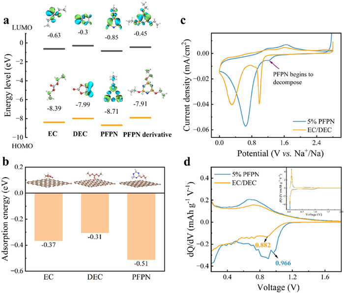
HOMO and LUMO of PFPN and solvent molecules were calculated by density-functional theory (DFT) to evaluate the electrochemical reduction and oxidation priority of molecules. As shown in the calculation results in Fig. 1a, PFPN exhibits the lowest LUMO energy level (−0.85 eV) among the molecules studied. This lower energy level indicates a greater propensity to accept electrons, facilitating its preferential reduction and subsequent participation in SEI formation. The lowest HOMO energy level of PFPN confers enhanced resistance to oxidative decomposition under high-voltage conditions [2,17,31]. Furthermore, the adsorption energy of PFPN on HC (−0.51 eV) is obviously larger than that of EC (−0.37 eV) and DEC (−0.31 eV), suggesting that PFPN predominantly resides in the inner Helmholtz layer of HC surface and preferentially accept electron to reduce (Fig. 1b and Fig. S3 in Supporting information) [32,33]. The decomposition behavior of electrolyte was revealed by cyclic voltammetry (CV) curves in Fig. 1c. The energy barrier for the ring-opening decomposition of PFPN, determined via DFT (Fig. S4 in Supporting information), indicates that the P-N bond (the phosphorus atom substituted with a fluorine atom and an ethoxy group) is the most vulnerable site for nucleophilic attack and reduction. The cleavage of this bond exhibits a lower energy barrier compared to other bonds. Under about 1.3 V, this bond undergoes reductive cleavage facilitated by Na+, leading to the formation of phosphorus-centered radicals. These radicals subsequently participate in polymerization reactions. The resulting polymers then react with sodium alkyl carbonates, ultimately generating NaF. These intermediates further decompose under the attack of Na+, yielding the final SEI components, which include NaF and nitrogen-rich species such as Na3N (Fig. S5 in Supporting information) [34-36]. As shown in Fig. S6 (Supporting information), the initial Coulombic efficiencies (ICEs) and corresponding dQ/dV curves of Na||HC half-cells (Fig. 1d) manifest the 5% PFPN electrolyte consumes some Na+ to decompose and participates in SEI formation in sodiation process, which leads to the significantly reduced ICE [37].
Figure 1
Figure 1.
(a) HOMO and LUMO energy levels of PFPN and solvent molecules. (b) The adsorption energy of PFPN and solvent molecules on the surface of HC. (c) First cycle voltammogram of Na||Cu cells with EC/DEC and 5% PFPN electrolytes at a scan rate of 0.2 mV/s between 0 and 2.8 V. (d) First cycle dQ/dV curves of Na||HC half-cells employing EC/DEC and 5% PFPN electrolytes at the current density of 0.02 A/g.
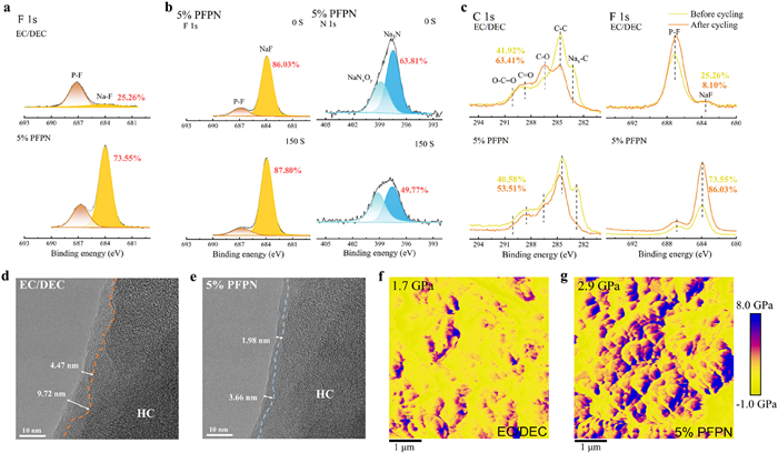
To further probe the effect of PFPN on the composition and spatial distribution characteristics of SEI, X-ray photoelectron spectroscopy (XPS) was performed. Fig. 2a and Fig. S7 (Supporting information) are the surface XPS spectra of SEI formed on HC before cycling. The C 1s peaks at 286.3 eV (C–O), 288.3 eV (C=O) and 289.8 eV (O=C-O) are mainly originated from some organic compounds, such as RONa and RCOCO2Na. The C–C peak represents the carbon base materials. The O=C-O and Na-O or CO32- peaks at 532.6 and 531.2 eV in O 1s spectrum belong to NaCO3R or Na2O. The C and O spectra contained species are mainly derived from the decomposition of carbonate solvents. The F 1s peak at 684.4 eV (NaF) and the peak at 133.3 eV (NaxPOy) of P 2p spectrum are regarded as the reduction products of NaPF6 salt. The NaxPOyFz (137.2 eV) peak in P 2p XPS spectrum is the hydrolysis decomposition products of NaPF6 [37-39]. The HC cycled in the 5% PFPN electrolyte reveals a significantly higher peak area ratio of NaF in F 1s spectrum (73.55%) compared to that in the EC/DEC electrolyte (25.26%) (Fig. S8 in Supporting information). The NaF component, characterized by a high LUMO energy level and a large band gap, endows SEI with reducing driving force of electron transfer and good electronic insulation ability, which effectively mitigates electron tunneling through the SEI, thereby improving interfacial stability [37]. Moreover, the increased NaF content can enhance the mechanical strength of SEI due to its intrinsically high Young's modulus [40,41]. And a greater proportion of NaxPOy inorganic content in the SEI generated in the 5% PFPN electrolyte compared to EC/DEC. Crucially, Na3N (397.4 eV) and NaNxOy (398.8 eV) components are detected in the SEI formed in the 5% PFPN electrolyte from N 1s spectrum. Na3N, possessing superior ionic conductivity and excellent mechanical properties, facilitates the formation of a robust and ionically conductive SEI, ultimately enhancing Na+ diffusion kinetics [35]. However, more organic compounds and NaxPOyFz are detected in the SEI formed in the EC/DEC electrolyte. The surface and 150 s sputtered depth spectra of SEI formed on HC after 200 cycles (Fig. 2b, Figs. S9 and S10 in Supporting information). For EC/DEC electrolytes, the relative abundances of C 1s and O 1s spectra containing organic species decrease with sputtering time, while the inorganic NaF and NaxPOy components increase significantly. This compositional gradient indicates an organic-rich outer layer and an inorganic-rich inner SEI structure. Nevertheless, the SEI in 5% PFPN electrolyte exhibits consistently higher peak area ratios for NaF and NaxPOy with etching, signifying elevated inorganic content from surface to the inner SEI. The Na₃N component shows a slight decrease in relative abundance from 63.81% at the surface to 49.77% in the bulk. Collectively, these results demonstrate that the 5% PFPN-derived SEI possesses a higher concentration of inorganic components (such as NaF, NaxPOy and Na3N) compared to the EC/DEC-derived SEI, consistently observed from the surface to the inner layer (Fig. S11 in Supporting information). The surface XPS spectra of the SEIs formed on HC before (after 3 cycles activation) and after 200 cycles cycling (Fig. 2c and Fig. S12 in Supporting information) reveal distinct compositional evolution. As shown in Fig. 2c, the intensity of the organic SEI species obviously increase after 200 cycles cycling (from 41.92% to 63.41%) and the content of NaF significantly decreases from 25.26% (after activation) to only 8.10% (after 200 cycles), which are attributed to the pronounced solvent decomposition during cycling in EC/DEC electrolyte. Notably, the SEI formed in 5% PFPN electrolyte shows significantly low growth degree of organic species (from 40.58% to 53.51%). The content of NaF increases from 73.55% to 86.03%, and the content of Na3N increases from 56.36% to 63.81% after cycling. This demonstrates the electrochemical stability of the PFPN-derived inorganic dominated SEI [42,43]. The abundant NaF and Na3N components within this SEI effectively mitigate severe parasitic reactions arising from continuous electrolyte decomposition and suppress SEI reconfiguration and uncontrolled thickening.
Figure 2
Figure 2.
(a) F 1s XPS spectra of SEI surface on HC anodes before cycling. (b) F 1s and N 1s XPS spectra of SEI surface and 30 nm depth (sputtering 150 s) on HC anode after 200 cycles cycling at 0.1 A/g in 5% PFPN electrolyte. (c) C 1s and F 1s XPS spectra of SEI surface formed on HC before and after 200 cycles cycling. TEM images of HC electrodes after cycling in (d) EC/DEC and (e) 5% PFPN electrolytes. DMT modulus mappings form AFM on HC anodes after cycling in (f) EC/DEC and (g) 5% PFPN electrolytes.
High-resolution transmission electron microscopy (HRTEM) images (Figs. 2d and e) further revealed a thinner (2–4 nm) and more uniform SEI formed in the 5% PFPN electrolyte compared to the EC/DEC-derived SEI. The mechanical properties of the SEI were further characterized using atomic force microscopy (AFM). As depicted in Figs. 2f and g and Fig. S13 (Supporting information), the SEI derived from the 5% PFPN electrolyte exhibits a higher relative Young's modulus (2.9 GPa) and a significantly lower relative average dissipation energy (−0.9 keV) compared to the SEI derived from the EC/DEC electrolyte, which is attributed to the abundant inorganic components stemming from the decomposion of PFPN, particularly NaF with high Young's modulus (76 GPa) [44]. In contrast, the SEI derived from the EC/DEC electrolyte shows a higher relative average dissipation energy (4.7 keV) and a much larger relative average surface roughness (Figs. S13 and S14 in Supporting information).
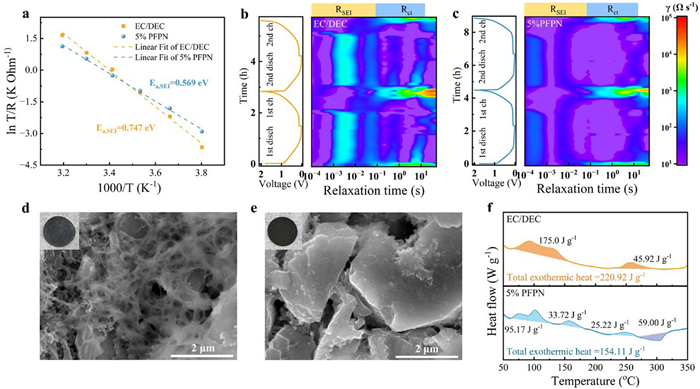
The kinetics of charge transfer within SEI was investigated via temperature-dependent electrochemical impedance spectroscopy (EIS) measurements. The activation energy of Na+ transport through SEI (Ea, SEI) is evaluated by the classic Arrhenius law. A significantly lower Ea, SEI value (0.569 eV) observed in 5% PFPN electrolyte versus the base electrolyte (0.747 eV) indicates markedly enhanced Na+ diffusion kinetics through the SEI (Fig. 3a, Fig. S15 and Table S1 in Supporting information). The inorganic-rich SEI featuring abundant phase boundaries and vacancy defects is conducive to Na+ diffusion in 5% PFPN electrolyte. And the Na3N compound, with high ionic conductivity, can accelerate ion migration through SEI [45,46]. Distribution of relaxation times (DRT) analysis employing in situ EIS was utilized to probe interfacial charge transfer processes (Figs. 3b and c, Fig. S16 in Supporting information). The peaks in the intermediate frequency region (10−4 s < τ < 10−1 s) are typically associated with the impedance change during SEI formation, including Na+ desolvation and subsequent Na+ transport through SEI (RSEI). Low frequency region (10−1 s < τ < 101 s) is commonly attributed to the faradaic charge transfer resistance (Rct) [35,47]. Significantly reduced RSEI and Rct values in the 5% PFPN system further reflect improved interfacial kinetics during sodiation/desodiation [48]. The highly ion-conductive, inorganic-rich SEI enables fast Na+ diffusion through the interphase and maintains a stable, low-impedance interface over cycling. Furthermore, ion transport kinetics within SEI is a critical determinant of sodium plating behavior. Non-uniform Na deposition arising from interfacial concentration polarization promotes dendrite formation and dead sodium accumulation during fast-charging, which not only degrades electrochemical performance but also poses significant safety hazards, including internal short circuit and thermal runaway [49,50]. Under fast-charging conditions (Fig. S24 in Supporting information), digital photos and scanning electron microscopy (SEM) analysis of HC anodes from Na||HC half-cells reveal distinct sodium deposition behavior (Figs. 3d and e). In EC/DEC electrolyte, HC surface exhibits extensive random sodium dendrite formation. Corresponding elemental mapping shows intense yet inhomogeneous sodium distribution after complete desodiation (Fig. S17 in Supporting information), indicating significant dead sodium accumulation. Conversely, the 5% PFPN electrolyte enables homogeneous and minimal sodium plating with faint surface deposition and dendrite-free morphology on HC surface (Fig. S18 in Supporting information). The SEI formed in the 5% PFPN electrolyte achieves enhanced interfacial kinetics through high ionic conductivity and accelerated Na+ flux. This enables obvious reduction of concentration polarization at the electrode interface, thereby effectively suppressing dendrite formation and dead sodium accumulation during fast-charging operation.
Figure 3
Figure 3.
(a) Arrhenius behavior of the resistance corresponding to Na+ transport through SEI. In-situ DRT data representing sodiation and desodiation process of Na||HC half-cells in (b) EC/DEC and (c) 5% PFPN electrolytes. Digital photos and SEM images of the HC anodes after 200 cycles cycling at 1 A/g in (d) EC/DEC and (e) 5% PFPN electrolytes, respectively. (f) DSC curves of fully discharged HC (after cycling 3 cycles at 0.02 A/g) mixing with relevant electrolyte at a scan rate of 10 ℃/min from 50 ℃ to 350 ℃.
Battery safety under operational conditions remains a critical concern. Charged (desodiated) cathodes and discharged (sodiated) anodes exhibit pronounced thermal vulnerability. At elevated temperatures, vigorous electrolyte/electrode reactions and accelerated electrolyte decomposition readily trigger thermal runaway, even fire and explosion [51]. Conventional SEIs further compromise safety due to their low thermal stability, decomposing at high temperatures and losing their passivating function on anode [52]. Differential scanning calorimetry (DSC) analysis of fully discharged HC anodes in respective electrolytes reveals the thermal behavior (Fig. 3f). All systems exhibit exothermic peaks near 67.5 ℃, with the EC/DEC electrolyte generating significantly higher exothermic heat (220.92 J/g) versus 5% PFPN system (154.11 J/g). Moreover, the 5% PFPN system displays a distinct endotherm at 267.8 ℃, deriving from decomposition of SEI inorganic components or electrolyte/SEI breakdown [53,54]. These findings further demonstrate the safety of 5% PFPN electrolyte, which can suppress thermal release reactions and mitigate the safety concerns associated with sodiated anode during the thermal-abuse scenarios through stable interfacial chemistry.
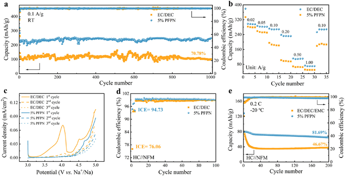
The specific impacts of 5% PFPN electrolyte on the electrochemical performance of HC anodes were investigated. As shown in Fig. S19, the introduction of 5 vol% PFPN does not cause a significant change in the ionic conductivity of the electrolyte. Fig. 4a presents the cycling performances of HC anode in both the EC/DEC and 5% PFPN electrolytes. Notably, the HC anode cycled in 5% PFPN electrolyte delivers a high reversible capacity of 248.5 mAh/g after 1000 cycles at 0.1 A/g, exhibiting negligible capacity attenuation. In contrast, using the EC/DEC electrolyte results in a significantly lower reversible capacity and a capacity retention of only 70.78% after 1000 cycles. This performance enhancement is attributed to the electrochemically stable SEI formed by PFPN-derived inorganic components. Critical species including NaF, Na3N and NaNxOy effectively suppress electron tunneling through the SEI while mitigating parasitic side reactions. Comparative experiments with classic single-function additives under identical conditions have been performed (Fig. S20 in Supporting information). The specific capacity achieved with the PFPN additive is higher than that obtained with FEC and TFEP additives. This results demonstrate the advantages of PFPN multifunctional additive. The rate performance of half cells was tested from the current density of 0.02 A/g to 1.0 A/g (Fig. 4b). The EC/DEC electrolyte exhibited a pronounced capacity drop at current densities exceeding 0.1 A/g. However, the 5% PFPN electrolyte emerges an obvious capacity decrease at the current density of 0.5 A/g. The galvanostatic charge/discharge curves of HC at different current density (Fig. S21 in Supporting information). The plateau capacity of HC in EC/DEC drops more than that in 5% PFPN electrolyte. Furthermore, it can be seen that the potential gap between the sodiation/desodiation peaks becomes progressively smaller when replacing EC/DEC electrolyte (73.1 mV) by 5% PFPN electrolyte (36.9 mV) at the current density of 0.1 A/g. The analysis of dQ/dV curves indicates that the 5% PFPN electrolyte significantly reduces electrode polarization, thereby contributing to the enhanced rate performance [55,56]. Linear sweep voltammetry (LSV) was employed to evaluate the anodic stability of electrolyte (Fig. 4c) [57]. The EC/DEC electrolyte undergoes vigorous oxidative decomposition at potentials exceeding 3.3 V (vs. Na+/Na), resulting in compromised NFM cathode performance. The 5% PFPN electrolyte demonstrates superior oxidation resistance, maintaining stability up to 4.25 V. As in previous studies [36,58]. PFPN can react with sodium alkyl carbonates to form alkoxyl groups-enriched PFPN derivatives. The PFPN derivatives characterized by high HOMO value are preferentially oxidized to produce inorganic compounds such as NaNxOy and NaxPOy at the cathode (Fig. 1a), which leads to the formation of a stable CEI and suppresses electrolyte continuous decomposition under high-voltage conditions. As evidenced by the LSV curves, the EC/DEC electrolyte exhibits an elevated current density during the second scan, indicating persistent oxidative decomposition due to inadequate CEI stability [59]. Conversely, the 5% PFPN electrolyte shows no significant current density increase in subsequent scans while demonstrating extended oxidation potential. The Na||NFM half-cell employing EC/DEC electrolyte displays a low capacity retention of 59.76% after 200 cycles, coupled with low ICE and average CE (Fig. S22a in Supporting information). In contrast, the incorporation of PFPN enables a higher capacity retention of 83.19% and an ICE of 91.99%, attributed to the formation of a stable CEI [60]. Furthermore, the Na||NFM cell utilizing the 5% PFPN electrolyte also demonstrates better rate capability (Fig. S22b in Supporting information).
Figure 4
Figure 4.
Electrochemical behaviors of EC/DEC and 5% PFPN electrolytes. (a) Long-term cycling performance of Na||HC half-cells at the current density of 0.1 A/g. (b) The rate performance of Na||HC half-cells at current densities of 0.02–1 A/g. (c) CV profiles of the two electrolytes at the scan rate of 0.2 mV/s for the oxidation process in Na||Al/Super P/PVDF cell (voltage range: 3.0–5.0 V vs. Na+/Na). (d) The CE of NFM||HC cells at a current density of 1 C. (e) Low-temperature long-term cycling performance of NFM||HC cells at a current density of 0.2 C under −20 ℃.
To evaluate the practical applicability of the 5% PFPN electrolyte, NFM||HC full cells were tested in different electrolytes. As shown in Fig. 4d and Fig. S23 (Supporting information), the cell employing 5% PFPN electrolyte demonstrates 73.26% capacity retention after 150 cycles with outstanding ICE of 94.73% and high average CE at a current density of 1 C (1 C = 130 mA/g), which strongly confirm the formation of effective PFPN-induced SEI and CEI. In contrast, the cell using the EC/DEC electrolyte shows a much lower ICE of only 76.06% and significantly reduced capacity retention. Remarkably, the NFM||HC cell assembled with 5% PFPN electrolyte achieves a high reversible specific capacity of 80.2 mAh/g at 0.2 C under −20 ℃, maintaining an impressive capacity retention of 81.69% after 200 cycles (Fig. 4e). The 5% PFPN electrolyte endows the HC||NFM full cell with competitive performance under −20 ℃ (Table S2 in Supporting information). In sharp contrast, the cell with the EC/DEC/EMC electrolyte (the baseline EC/DEC electrolyte was substituted with EC/DEC/EMC (2:4:4, v/v/v) electrolyte to improve low-temperature suitability) suffers from rapid capacity decay, retaining only 46.67%. The inorganic-rich SEI with high ionic conductivity ensures efficient Na+ transport across the SEI under low–temperature conditions, contributing substantially to the reduced activation energy for Na+ migration at −20 ℃. This mechanism is crucial for the observed markedly improved low–temperature performance. Therefore, 5% PFPN electrolyte demonstrates superior high-voltage performance and low-temperature operability.
In summary, this study demonstrates that the incorporation of PFPN as a multifunctional additive facilitates the establishment of a stable and highly conductive electrode/electrolyte interface, leading to significantly enhanced electrochemical performance in SIBs. The preferential decomposition of PFPN on HC anode, attributed to its low LUMO and strong adsorption, results in the formation of a robust SEI enriched with NaF and Na3N. NaF possesses high Young's modulus and good electronic insulation ability and Na3N is characterized by high ionic conductivity, which endow the SEI with superior structural/electrochemical stability and significantly low Ea, SEI (0.569 eV) and promote homogeneous Na deposition on HC anode. Especially, the use of PFPN enables nonflammable electrolyte and reduces the thermal release reactions at the electrode/electrolyte interface, thereby mitigating the concerns about thermal runaway risk. As a result, the HC||Na cell with PFPN additive delivers a high reversible capacity of 248.5 mAh/g with negligible capacity decay after 1000 cycles at 0.1 A/g. The NaNi0.33Fe0.33Mn0.33O2 (NFM)||HC full cell also demonstrates improved cycling stability and retains a capacity retention rate of 81.69% after 200 cycles under −20 ℃. This work offers an effective strategy for designing high-safety and high-performance electrolytes, thereby contributing to the advancement of the commercialization of SIBs.
Declaration of competing interest
The authors declare that they have no known competing financial interests or personal relationships that could have appeared to influence the work reported in this paper.
This work was supported by the National Natural Science Foundation of China (Nos. 22579041 and 22209187), the Natural Science Foundation of Heilongjiang Province (No. YQ2024B005), the State Key Laboratory of Urban Water Resource and Environment (Harbin Institute of Technology) (No. 2022TS19) and the Fundamental Research Funds for the Central Universities (No. HIT.OCEF.2024006). The authors extend their gratitude to the Theoretical and Computational Chemistry Team from Scientific Compass (www.shiyaniia.com) for providing invaluable assistance.
Supplementary materials
Supplementary material associated with this article can be found, in the online version, at doi:10.1016/j.cclet.2025.112348.
[1]
Z.N. Tian, Y. Zou, G. Liu, et al., Adv. Sci. 9 (2022) 2201207. doi: 10.1002/advs.202201207
[2]
E. Wang, Y. Niu, Y.X. Yin, Y.G. Guo, ACS Mater. Lett. 3 (2020) 18–41.
[3]
J. Chen, Z. Yang, X. Xu, et al., Adv. Mater. 36 (2024) 2400169. doi: 10.1002/adma.202400169
[4]
M. Li, S. Sui, X. Zhou, et al., Angew. Chem. Int. Ed. 64 (2025) e202515062. doi: 10.1002/anie.202515062
[5]
Y. Wan, X. Shi, Z. Zhou, et al., J. Am. Chem. Soc. 147 (2025) 29939–29948. doi: 10.1021/jacs.5c07004
[6]
J. Chen, J. Xiao, S. Liao, et al., Energy Storage Mater. 82 (2025) 104631. doi: 10.1016/j.ensm.2025.104631
M. Niu, L. Dong, X. Chen, et al., Natl. Sci. Rev. 12 (2025) nwaf065. doi: 10.1093/nsr/nwaf065
[55]
X.Y. Zheng, Z. Cao, W. Luo, et al., Adv. Mater. 35 (2023) 2210115. doi: 10.1002/adma.202210115
[56]
X.L. Yi, X. Li, J. Zhong, et al., Adv. Funct. Mater. 32 (2022) 2209523. doi: 10.1002/adfm.202209523
[57]
P.T. Xiao, Y. Zhao, Z. Piao, et al., Energy Environ. Sci. 15 (2022) 2435–2444. doi: 10.1039/D1EE02959B
[58]
E.M. Li, L. Liao, J. Huang, et al., Energy Storage Mater. 73 (2024) 103805. doi: 10.1016/j.ensm.2024.103805
[59]
Y.G. Zou, B. Zhang, H. Luo, et al., Adv. Mater. 36 (2024) 2410261. doi: 10.1002/adma.202410261
[60]
J.W. Chen, Y. Peng, Y. Yin, et al., Energy Environ. Sci. 15 (2022) 3360–3368. doi: 10.1039/D2EE01257J
Figure 1
(a) HOMO and LUMO energy levels of PFPN and solvent molecules. (b) The adsorption energy of PFPN and solvent molecules on the surface of HC. (c) First cycle voltammogram of Na||Cu cells with EC/DEC and 5% PFPN electrolytes at a scan rate of 0.2 mV/s between 0 and 2.8 V. (d) First cycle dQ/dV curves of Na||HC half-cells employing EC/DEC and 5% PFPN electrolytes at the current density of 0.02 A/g.
Figure 2
(a) F 1s XPS spectra of SEI surface on HC anodes before cycling. (b) F 1s and N 1s XPS spectra of SEI surface and 30 nm depth (sputtering 150 s) on HC anode after 200 cycles cycling at 0.1 A/g in 5% PFPN electrolyte. (c) C 1s and F 1s XPS spectra of SEI surface formed on HC before and after 200 cycles cycling. TEM images of HC electrodes after cycling in (d) EC/DEC and (e) 5% PFPN electrolytes. DMT modulus mappings form AFM on HC anodes after cycling in (f) EC/DEC and (g) 5% PFPN electrolytes.
Figure 3
(a) Arrhenius behavior of the resistance corresponding to Na+ transport through SEI. In-situ DRT data representing sodiation and desodiation process of Na||HC half-cells in (b) EC/DEC and (c) 5% PFPN electrolytes. Digital photos and SEM images of the HC anodes after 200 cycles cycling at 1 A/g in (d) EC/DEC and (e) 5% PFPN electrolytes, respectively. (f) DSC curves of fully discharged HC (after cycling 3 cycles at 0.02 A/g) mixing with relevant electrolyte at a scan rate of 10 ℃/min from 50 ℃ to 350 ℃.
Figure 4
Electrochemical behaviors of EC/DEC and 5% PFPN electrolytes. (a) Long-term cycling performance of Na||HC half-cells at the current density of 0.1 A/g. (b) The rate performance of Na||HC half-cells at current densities of 0.02–1 A/g. (c) CV profiles of the two electrolytes at the scan rate of 0.2 mV/s for the oxidation process in Na||Al/Super P/PVDF cell (voltage range: 3.0–5.0 V vs. Na+/Na). (d) The CE of NFM||HC cells at a current density of 1 C. (e) Low-temperature long-term cycling performance of NFM||HC cells at a current density of 0.2 C under −20 ℃.

 DownLoad:

 下载:
下载:


 下载:
下载:
