Citation:
Sili Qing, Yuxi Xu, Shuai Gao, Li-Ping Jiang, Xiaoge Wu, Wenlei Zhu. An efficient and sustainable hybrid electrochemical system for heterogeneous electro-Fenton degradation of phenolic pollutants[J]. Chinese Chemical Letters,
2026, 37(7): 112193.
doi:
10.1016/j.cclet.2025.112193
An efficient and sustainable hybrid electrochemical system for heterogeneous electro-Fenton degradation of phenolic pollutants
English
An efficient and sustainable hybrid electrochemical system for heterogeneous electro-Fenton degradation of phenolic pollutants
State Key Laboratory of Pollution Control and Resource Reuse, State Key Laboratory of Analytical Chemistry for Life Science, School of the Environment, School of Chemistry and Chemical Engineering, the Frontiers Science Center for Critical Earth Material Cycling, Nanjing University, Nanjing 210023, China
b.
Environment Science and Engineering College, Yangzhou University, Yangzhou 225009, China
c.
Biomass group, College of Engineering, Nanjing Agricultural University, Nanjing 210031, China
Received Date:
14 May 2025 Accepted Date:
26 November 2025 Revised Date:
11 November 2025 Available Online:
15 July 2026
Abstract:
The heterogeneous electro-Fenton (HEF) technology is a promising yet challenging approach for organic pollutant degradation. It is urgent to develop a catalyst for both highly efficient H2O2 and hydroxyl radical (•OH) generation with low energy consumption at neutral conditions. This study presents a bifunctional catalyst (CoPc/OCNTs/FeOF) synthesized by ultrasonic anchoring of FeOF onto cobalt phthalocyanine-modified oxidized carbon nanotubes. The catalyst demonstrated synergistic effects, achieving a 2.94-fold enhancement in H2O2 generation and a 3.85-fold increase in •OH yield compared to its individual components (CoPc/OCNTs and FeOF). At pH 6, the CoPc/OCNTs/FeOF cathode enabled nearly complete phenol removal within 90 min, with a high kinetic rate constant (k) of 0.04848 min-1, driven by cooperative oxidation from singlet oxygen (1O2) and •OH. The system exhibited exceptional stability, inorganic ion tolerance, and broad applicability to real wastewaters, achieving 82.0% total organic carbon (TOC) removal for phenol wastewater at a low energy consumption of 21.9 kWh kg-1 COD-1. Moreover, sodium alginate-immobilized microalgae hydrogel was integrated into the HEF system to supply O2in situ for the 2e- oxygen reduction reaction (ORR), eliminating energy-intensive mechanical aeration. Subsequent microalgal cultivation further removed 90.6% of total nitrogen and 82.8% of total phosphorus, showcasing a sustainable dual-function strategy for pollutant degradation and nutrient recovery. This work advances the design of efficient HEF catalysts and highlights the potential of microalgae-coupled systems for sustainable wastewater treatment.
Emerging organic pollutants (EOPs) in aquatic environments are toxic and resistant to conventional wastewater treatment processes, posing serious threats to the ecosystems and human health [1,2]. Advanced oxidation processes (AOPs) that produce reactive oxygen species (ROS) are considered a useful method for removing EOPs [3-5]. However, most traditional AOPs require large amounts of chemical inputs and additional post-processing, thereby increasing operational costs and hindering their practical application in wastewater treatment [6,7].
Recently, the heterogeneous electro-Fenton (HEF) system, which provides an eco-friendly and sustainable approach for H2O2 and hydroxyl radical (•OH) generation, has garnered considerable interest [8-10]. In the HEF system, the electrocatalytic oxygen reduction reaction (ORR) enables the in situ generation of H2O2 through a two-electron ORR pathway, followed by its stepwise activation into •OH (Eqs. 1-5). The high standard redox potential of •OH (2.8 V vs. SHE) allows it to oxidize and degrade most refractory organic pollutants in wastewater [11]. This process effectively overcomes several inherent limitations of conventional Fenton processes, including external H2O2 addition, strict pH dependence, iron sludge formation, and catalyst recycling issues [12].
Despite its advantages, the practical application of HEF faces two major challenges: (ⅰ) The need for efficient bifunctional catalysts that simultaneously promote high yield of H2O2 generation and •OH production, and (ⅱ) the energy-intensive aeration typically required for O2 supply in the 2e- ORR process. Recent studies have explored carbon-based materials (e.g., carbon nanotubes, nitrogen-doped carbon) as supports for Fenton-active metals to enhance electron transfer and catalytic stability [13,14]. However, most reported iron-containing HEF cathodes, such as FeOCl [15], zero-valent iron (Fe0) [16], and Fe3O4 [17], perform well only under acidic conditions but exhibit drastically reduced activity under neutral conditions. These heterogeneous catalysts suffer from slow Fe(Ⅱ)/Fe(Ⅲ) cycling kinetics (Eq. 4) and inefficient electron transfer (Eq. 5), resulting in ineffective H2O2 decomposition [18]. In addition, the Fenton reactive sites usually affect the H2O2 selectivity of carbon-based materials, resulting in low H2O2 yields and current efficiencies in practical applications [19]. The degradation capacity of HEF is predominantly governed by both the production and utilization efficiency of H2O2. Therefore, the rational design of advanced bifunctional catalysts capable of simultaneously driving H2O2 production and its activation to •OH is critically important.
Additionally, mechanical aeration remains a key energy bottleneck in HEF systems. For example, conventional mechanical aeration represents a major energy burden (≥50% of power costs in wastewater treatment plants) [20]. Introducing green algae (photosynthetic microorganism) into HEF systems is expected to solve this problem. Our previous work demonstrated that functionalized microalgae could effectively enhance 4e– ORR performance through in situ oxygen supply [21]. Moreover, microalgae have been applied for removing pollutants by coupling with photocatalysts (e.g., BiVO4, g-C3N4 and TiO2) under moderate reaction conditions [22-24]. Nevertheless, the removal efficiency remained unsatisfactory with slow kinetics (requiring at least 19 h for complete removal). The primary degradation mechanism was driven by the induced moderate oxidative stress in algae. In contrast, the role of ROS produced by photocatalysts was relatively minor, primarily due to microalgal cells' susceptibility to damage from high-concentration ROS [25]. Sodium alginate-immobilized microalgae (SA/algae) hydrogel has demonstrated dual functionality in biomass cultivation and wastewater remediation [26], while their application in electrochemical systems remains unreported. Therefore, we propose introducing SA/algae (Chlorella pyrenoidosa) hydrogel to protect cell viability in HEF system. This SA/algae hydrogel is expected to simultaneously provide O2 for the HEF system and recover nutrients (e.g., N and P) from real wastewater [27].
To address these limitations, we developed a CoPc/OCNTs/FeOF composite catalyst, where FeOF nanoparticles were anchored onto cobalt phthalocyanine-functionalized oxidized carbon nanotubes (CoPc/OCNTs) via ultrasonic synthesis (Fig. 1a). This design leveraged (i) The high ORR activity of CoPc/OCNTs for selective H2O2 production, and (ii) the superior Fenton-like reactivity of FeOF for •OH generation. Additionally, the degradation performance, stability and the influence of various operational parameters on removal efficiency were systematically studied. Furthermore, we introduced a novel microalgae-hydrogel system to replace energy-intensive mechanical aeration, enabling sustainable oxygen supply through algal photosynthesis while simultaneously facilitating nutrient removal (N/P) from treated wastewater. To the best of our knowledge, this is the first study to combine a high-efficiency HEF catalyst with a self-sustaining microalgal O2 supply system, offering a blueprint for energy-neutral wastewater treatment.
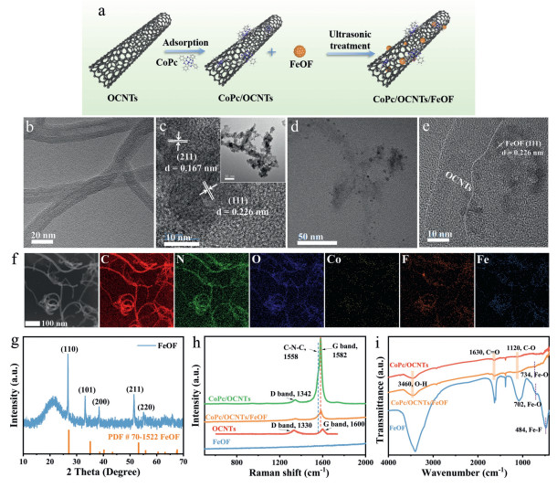
Figure 1
Figure 1.
(a) Scheme of preparation of CoPc/OCNTs/FeOF. HRTEM images of (b) CoPc/OCNTs and (c) FeOF (inset: its TEM image; scale bar, 50 nm). (d) CoPc/OCNTs/FeOF and (e) its enlarged image. (f) The STEM image of CoPc/OCNTs/FeOF and its EDS mapping images. (g) XRD patterns of FeOF. (h) Raman spectra. (i) FTIR spectra.
OCNTs were synthesized by oxidative treatment using concentrated nitric acid to create oxygen functional groups on the surface of pristine CNTs. CoPc/OCNTs catalysts were prepared by anchoring CoPc molecules onto the sidewalls of OCNTs via noncovalent π-π interactions in dimethylformamide [28]. Transmission electron microscopic (TEM) images (Figs. S1a and b in Supporting information) revealed that OCNTs exhibited rough tubular nanostructure compared to the smooth surfaces of pristine CNTs, resulting from the chemical oxidation and exfoliation in nitric acid. Besides, Raman spectra (Fig. S1c in Supporting information) of CNTs and OCNTs showed broad D and G bands at ~1327.4 and ~1585.7 cm-1, respectively [29]. The Raman intensity ratio of the D and G band (ID/IG) for OCNTs was significantly increased compared to that of pristine CNTs, indicating the introduction of more defects on OCNTs surfaces via oxidation processes [30]. X-ray diffraction (XRD) patterns of CoPc/OCNTs (Fig. S1d in Supporting information) displayed diffraction peaks at 26.0°, 42.9°, and 53.5°, corresponding to the (002), (100), and (004) planes of graphitic carbon, respectively, consistent with the structure of OCNTs [31]. The inductively coupled plasma atomic emission spectroscopy (ICP-AES) revealed a CoPc mass loading of 5.36 wt% on CoPc/OCNTs. High-resolution transmission electron microscopy (HRTEM) (Fig. 1b) showed that CoPc/OCNTs demonstrated an individual nanotube structure with the CoPc molecular-assembly.
The FeOF catalyst was prepared by obtaining FeSiF6·6H2O from dissolving iron powders in fluorosilicic acid (H2SiF6) aqueous solution, followed by a solvothermal reaction [32]. TEM images (Fig. 1c) showed that FeOF formed aggregated granular nanostructures, consistent with the scanning electron microscopy (SEM) image (Fig. S2a in Supporting information). A lattice finger distance of 0.226 nm and 0.167 nm could be observed in the HRTEM image (Fig. 1c), representing the (111) and (211) facets of FeOF, respectively [32]. The HRTEM image (Figs. 1d and e) demonstrated the uniform dispersion of FeOF nanoparticles on the surface of CoPc/OCNTs. Furthermore, scanning transmission electron microscopy (STEM) combined with energy dispersive X-ray spectroscopy (EDS) analysis (Fig. 1f) confirmed the homogeneous distribution of all elements (C, N, O, Co, Fe, and F) throughout the CoPc/OCNTs/FeOF composite. XRD patterns of FeSiF6·6H2O and FeOF (Fig. S2b in Supporting information and Fig. 1g) clearly well matched the standard cards PDF #26–0799 and PDF #70–1522, respectively [33], confirming the successful fabrication of catalysts. To further prove the successful anchoring of FeOF nanoparticles on CoPc/OCNTs, Raman spectroscopy, Fourier transform infrared spectroscopy (FTIR) and X-ray photoelectron spectroscopy (XPS) were measured. Raman spectra (Fig. 1h) exhibited two characteristic bands for CoPc/OCNTs at 1342 cm-1 and 1582 cm-1, corresponding to the D band and G bands of carbon materials, respectively. Notably, a peak at 1558 cm-1 appeared in both CoPc/OCNTs and CoPc/OCNTs/FeOF, attributed to the vibration of C–N–C bridge bonds between the isoindole units of CoPc molecules [34]. In addition, FTIR analysis (Fig. 1i) revealed multiple stretching vibrations of oxygen-containing groups at ~1120 cm-1 (C–O), ~1630 cm-1 (C = O), and ~3460 cm-1 (O–H) in OCNTs, CoPc/OCNTs and CoPc/OCNTs/FeOF [35]. The characteristic peaks of FeOF at 702 cm-1 and 484 cm-1 were assigned to the stretching vibration of Fe–O bonds and Fe–F bonds, respectively [36]. The F–O bond also appeared in the composite materials at a slightly higher wavenumber (734 cm-1), indicating that an interaction occurred between CoPc/OCNTs and FeOF.
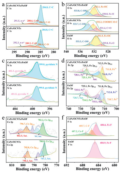
XPS spectra were used to acquire additional structural information of CoPc/OCNTs, FeOF and CoPc/OCNTs/FeOF (Fig. 2). The high-resolution C 1s spectrum (Fig. 2a) of CoPc/OCNTs/FeOF could be deconvolved into four components, corresponding to the C=C (284.8 eV), C–O (286.5 eV), C=O (288.6 eV), and π-π* transition (291.5 eV), respectively [37]. The O 1s spectrum (Fig. 2b) showed three deconvoluted peaks at 530.8, 532.1 and 533.8 eV, corresponding to Fe–O, Fe–OC and C–OH coordination compounds [38].
Figure 2
Figure 2.
(a-f) High-resolution C 1s, O 1s, N 1s, Fe 2p, Co 2p and F 1s XPS spectra of CoPc/OCNTs, FeOF and CoPc/OCNTs/FeOF.
The N 1s spectrum (Fig. 2c) of CoPc/OCNTs/FeOF showed peaks centered at 399 eV and 402.3 eV, corresponding to pyridinic N and pyrrolic N species, respectively [39]. The XPS spectrum of Fe 2p in CoPc/OCNTs/FeOF (Fig. 2d) exhibited two deconvoluted peaks at 725.3 eV and 712.3 eV, assigned to the Fe 2p1/2 and Fe 2p3/2, with a small shift to higher binding energy compared to that of FeOF [40]. Meanwhile, Fe2+peaks were centered at 711.8 eV and 725.1 eV, while Fe3+ peaks appeared at 714.8 eV and 728.1 eV, reflecting the coexistence of Fe(Ⅱ) and Fe(Ⅲ) on the surface of FeOF. Besides, two peaks appeared in the Co 2p XPS spectrum (Fig. 2e) at 782.2 eV and 796.7 eV, corresponding to the Co 2p3/2 and Co 2p1/2 signals, respectively [37]. The two shake-up satellites at 787 and 802.5 eV confirmed the existence of Co2+ in the composite materials [41]. The peak position of metallic Co shifted to a higher binding energy region after FeOF loading, suggesting electronics reconstruction during ultrasonication, likely due to fluorine's strong electronegativity [42]. The F 1s spectrum (Fig. 2f) revealed three peaks at 684.6, 685.7, and 687.2 eV, assigned to Fe–F, C–F and Co–F bonds, respectively [36,41,43]. These results supported the successful fabrication of the hybrid materials.
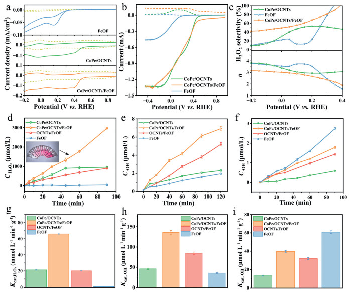
The electrochemical properties of FeOF, CoPc/OCNTs and CoPc/OCNTs/FeOF towards the ORR were evaluated by cyclic voltammetry (CV) in N2 and O2-saturated 0.1 mol/L Na2SO4 solutions (Fig. 3a). Typically, all the materials clearly exhibited reduction currents in O2-saturated solutions compared to N2 conditions. The onset potential of FeOF appeared at 0.30 V (vs. RHE), corresponding to a large overpotential for the 2e– ORR (theoretical E0 = 0.70 vs. RHE) [44], indicating poor ORR performance. In contrast, CoPc/OCNTs displayed a higher onset potential (0.48 V vs. RHE), suggesting that CoPc/OCNTs displayed a pronounced ORR activity. No obvious changes in the onset potential and limiting currents were observed in CoPc/OCNTs/FeOF composites.
Figure 3
Figure 3.
ORR performance of FeOF, CoPc/OCNTs and CoPc/OCNTs/FeOF. (a) CV curves of different catalysts in N2 or O2-saturated 0.1 mol/L Na2SO4 solutions (scan rate: 10 mV/s, pH 6). (b) LSV curves of catalysts obtained on RRDE at 1600 rpm (scan rate: 10 mV/s, pH 6). Solid lines: disk current density; dotted lines: ring current density. (c) H2O2 selectivity and number of transferred electrons (n). (d) H2O2 concentrations produced at −0.4 V (vs. Ag/AgCl) and (g) corresponding Kcat, H2O2 values within 90 min (catalyst loading: 0.5 mg; electrolyte: 15 mL). (e) •OH concentrations at −0.4 V (vs. Ag/AgCl) and (h) corresponding Kcat, •OH values within 90 min. (catalyst loading: 0.5 mg; electrolyte: 15 mL). (f) •OH concentrations produced from the activation of H2O2 in N2-saturated Na2SO4 electrolytes containing 5 mmol/L H2O2 and (i) corresponding Kcat, •OH values within 90 min.
Rotating ring-disk electrode (RRDE) was used to further estimate the ORR performance. The linear sweep voltammetry (LSV) curves in Fig. 3b revealed onset potentials of 0.19, 0.51, 0.51 V (vs. RHE) for FeOF, CoPc/OCNTs and CoPc/OCNTs/FeOF, respectively. The current density of FeOF, CoPc/OCNT and CoPc/OCNT/FeOF at −0.4 V (vs. Ag/AgCl) was 0.037, 0.78, and 0.78 mA, respectively. Moreover, CoPc/OCNTs/FeOF exhibited a H2O2 selectivity of 60.7% at −0.4 V (vs. Ag/AgCl), with an electron-transfer number of 2.79 (Fig. 3c). The H2O2 selectivity was higher than that of CoPc/OCNT (51.5%) and FeOF (13.4%). FeOF anchoring preserved the onset potential and limiting currents of CoPc/OCNTs, while the composite's higher H2O2 selectivity (60.7% vs. 51.5%) indicated that FeOF promoted the 2e- ORR pathway. It is speculated that fluorine coordination in FeOF may redistribute charge within the carbon framework of CoPc/OCNTs, thereby improving 2e– ORR selectivity [30].
The conductivity of catalysts was evaluated by electrochemical impedance spectroscopy (EIS). The charge transfer resistance (Rct) reflects the electron transfer resistance and a smaller arc radius size in the Nyquist plot means a smaller Rct [35]. The Nyquist plot in Fig. S3 (Supporting information) showed that the Rct values for CNTs, OCNTs, CoPc/OCNTs, CoPc/OCNTs/FeOF and FeOF were 26.99, 27.78, 31, 99, 50, 39 and 796.5 Ω, respectively. Notably, the Rct of CoPc/OCNTs/FeOF (50.39 Ω) was 15.8-fold lower than that of FeOF (796.5 Ω), confirming that OCNTs mitigated the insulating behavior of FeOF and facilitated the Fe(Ⅱ)/Fe(Ⅲ) redox cycling.
The H2O2 production was measured and the production rate was normalized by per unit mass of the catalysts (Kcat, H2O2) (Figs. 3d and g and Fig. S4 in Supporting information). The H2O2 concentration of CoPc/OCNTs/FeOF reached 2.971 mmol/L at 90 min, with a Kcat, H2O2 of 67.81 mmol L-1 min-1 g-1, which was 3.1, 2.94 and 28.5 times higher than that of OCNTs/FeOF (21.90 mmol L-1 min-1 g-1), CoPc/OCNTs (23.09 mmol L-1 min-1 g-1) and FeOF (2.38 mmol L-1 min-1 g-1), respectively. The synergistic effect between CoPc/OCNTs (primary H2O2 generation sites) and FeOF (a modulator of 2e- ORR selectivity) was critical to this performance. Additionally, cobalt phthalocyanine has been reported as a monometallic catalyst with high 2e– ORR activity and selectivity under neutral conditions, requiring a low overpotential [37]. Therefore, the H2O2 production of CoPc/OCNTs/FeOF was higher than that of OCNTs/FeOF. To probe the reaction intermediates over the catalysts, in situ FTIR measurements were performed in a custom-designed thin-layer electrochemical cell (Fig. S5 in Supporting information). An absorption band at 1254 cm-1 was observed on CoPc/OCNTs/FeOF, corresponding to the O–O stretching mode of surface-adsorbed *OOH [45], which confirmed the formation of *OOH intermediates during the HEF process. The band intensity increased as the potential decreased from −0.1 V to −0.6 V (vs. Ag/AgCl). Additionally, a weak absorption at 1254 cm-1 was detected on CoPc/OCNTs, while no obvious absorption was observed for FeOF. The result suggests a greater accumulation of *OOH intermediate on CoPc/OCNTs/FeOF compared to those on CoPc/OCNTs and FeOF, which is vital for H2O2 generation.
Quantitative analysis of •OH (Fig. 3e and Fig. S6 in Supporting information) revealed that CoPc/OCNTs/FeOF produced 6.12 μmol/L •OH at 90 min, surpassing CoPc/OCNTs (2.1 μmol/L), OCNTs/FeOF (3.80 μmol/L), and FeOF (1.59 μmol/L) by factors of 2.91, 1.61, and 3.85, respectively. Normalizing by the catalyst mass, the •OH production rate (Kcat, •OH) reached 136 μmol L-1 min-1 g-1, significantly higher than individual components (Fig. 3h), confirming efficient H2O2-to-•OH conversion at FeOF sites. Furthermore, a series of CoPc/OCNTs/FeOF (x:y) with different mass ratios (x:y = 4:2,4:3, 4:4, 3:4) were synthesized to investigate •OH production. As shown in Fig. S7 (Supporting information), the CoPc/OCNTs/FeOF (4:3) cathode displayed the highest •OH production, indicating that the synergistic effect for both high H2O2 and •OH yield was achieved only with the appropriate mass ratios. Decreasing the amount of CoPc/OCNTs may reduce H2O2 production, while decreasing the amount of FeOF may suppress the conversion of H2O2 to •OH.
Notably, the individual FeOF exhibited low electrocatalytic activity for both •OH and H2O2 production, likely due to its inferior 2e- ORR performance caused by slow electron transfer (Fig. S3). When it was anchored on CoPc/OCNTs, the sufficient H2O2 production and enhanced conductivity promoted FeOF-mediated H2O2 decomposition to •OH. Moreover, CoPc/OCNTs/FeOF achieved significantly higher H2O2 and •OH production rate than individual CoPc/OCNTs, demonstrating that FeOF sites were responsible for •OH generation and played a critical role in tuning the 2e– ORR selectivity. To probe the catalytic roles of individual components in H2O2 activation, we evaluated •OH generation in N2-saturated 0.1 mol/L Na2SO4 with 5 mmol/L H2O2 (to exclude O2 interference). As shown in Figs. 3f and i, FeOF and CoPc/OCNTs/FeOF exhibited higher Kcat, •OH values of 60.82 and 39.71 μmol L-1 min-1 g-1, respectively, compared to CoPc/OCNTs and OCNTs/FeOF. The highest H2O2 decomposition efficiency verified that FeOF was the main active site, consistent with its reported role in homogeneous Fenton reactions [32]. Therefore, we concluded that the efficient •OH electrogeneration arose from the cooperative catalysis between CoPc/OCNTs and FeOF: H2O2 was generated mainly at CoPc/OCNTs, while FeOF activated the in situ-formed H2O2 into •OH. The H2O2 and •OH production rates of CoPc/OCNTs/FeOF surpassed those of most reported HEF catalysts (Table S1 in Supporting information).
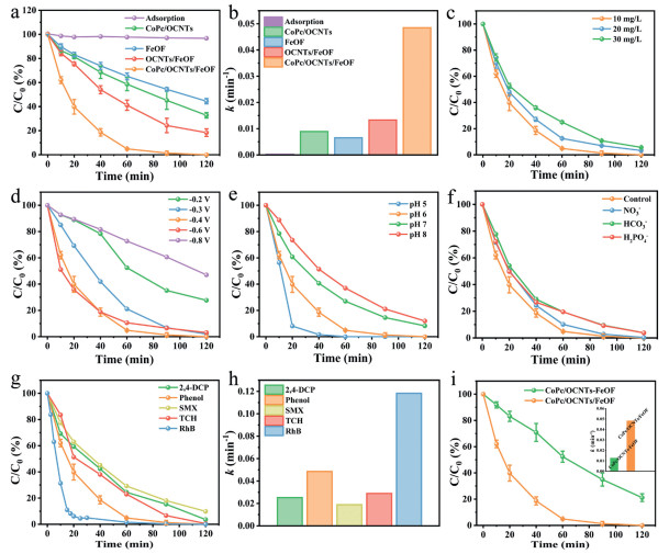
The degradation efficiency of CoPc/OCNTs/FeOF was evaluated via the HEF process using phenol—a persistent priority pollutant—as the model contaminant [46]. As shown in Fig. 4a, 98.7% phenol removal was achieved by CoPc/OCNTs/FeOF within 90 min, surpassing the performance of CoPc/OCNTs (54.8%), OCNTs/FeOF (75.7%) and FeOF (45.7%). Only 2.93% of phenol was removed by adsorption, indicating the HEF process as the dominant degradation mechanism. The degradation followed the pseudo-first-order kinetics and the kinetic rate constant (k) of CoPc/OCNTs/FeOF was calculated to be 0.04848 min-1 (mass-normalized rate constant = 48.48 min-1 g-1), representing 5.44, 3.64, and 7.45-fold enhancements over CoPc/OCNTs (0.00891 min-1), OCNTs/FeOF (0.01331 min-1), FeOF (0.00651 min-1), respectively (Fig. 4b). The phenol removal kinetics correlated well with their •OH electrogeneration activity discussed above. Even at elevated phenol concentrations (20–30 mg/L), the system maintained high removal efficiencies of 96.7% and 94.3% (Fig. 4c).
Figure 4
Figure 4.
(a) Phenol degradation curves and (b) corresponding k values. Influence of (c) phenol concentration, (d) cathode potential, (e) initial pH and (f) various inorganic ions (each at 5 mmol/L) on the degradation efficiency of CoPc/OCNTs/FeOF. (g) Degradation performance of CoPc/OCNTs/FeOF for various pollutants and (h) corresponding k values. (i) Comparison of CoPc/OCNTs/FeOF cathode and CoPc/OCNTs-FeOF solutions on the degradation of phenol (inset: corresponding k values). Pollutants: 10 mg/L; potential: −0.4 V (vs. Ag/AgCl); catalyst loading: 1 mg/cm2; O2: 100 mL/min; electrolyte: 20 mL, 0.1 mol/L Na2SO4 solution (pH 6).
Subsequently, the optimal cathode potential for phenol degradation was systematically explored in the CoPc/OCNTs/FeOF system (Fig. 4d). Phenol degradation efficiency exhibited strong potential dependence and reached its maximum at −0.4 V (vs. Ag/AgCl). The removal efficiency declined significantly above −0.3 V or below −0.6 V, as insufficient •OH accumulation occurred at lower potentials, while higher potentials resulted in the competitive hydrogen evolution reaction [47]. In addition, the influence of initial solution pH was evaluated as it affected both the iron leaching and the reactivity [48]. As depicted in Fig. 4e, the removal performance was optimal at pH 5, with a slight decrease to 88.1% when the pH increased to 8, demonstrating that CoPc/OCNTs/FeOF exhibited superior performance in acidic solutions and could effectively broaden the pH applicable ranges to 5–8 for pollutants degradation. To assess practical applicability, the system's tolerance to inorganic anions (common in wastewater) was tested. As presented in Fig. 4f, the phenol removal efficiencies were 99.7%, 96.2% and 96.1% in the presence of NO3–, H2PO4– and HCO3–, respectively. This result indicated the CoPc/OCNTs/FeOF exhibited a good resistance to interference from common inorganic anions.
Furthermore, a wide range of refractory organic pollutants was selected to evaluate the versatility of CoPc/OCNTs/FeOF HEF systems. As presented in Figs. 4g and h, satisfactory removal rates were achieved for 2,4-dichlorophenol (2,4-DCP, 96.4%), sulfamethoxazole (SMX, 90.1%), tetracycline hydrochloride (TCH, 99.5%), and Rhodamine B (RhB, 100%) within 120 min with k values of 0.0252, 0.01885, 0.0289 and 0.1182 min-1, respectively. Additionally, we explored another heterogeneous electro-Fenton system composed of the CoPc/OCNTs cathode and FeOF (suspended solid Fenton-like catalysts) (CoPc/OCNTs-FeOF). As shown in Fig. 4i, CoPc/OCNTs-FeOF system achieved only 78.9% phenol removal within 120 min, with a k value of 0.01354 min-1, which was 3.58 times lower than that of CoPc/OCNTs/FeOF HEF system. Upon increasing the amount of FeOF nanoparticles to 2 mg, the removal rate raised up to 100% (Fig. S8 in Supporting information), verifying •OH generation as the bottleneck. The result suggests that the CoPc/OCNTs/FeOF possesses higher mass activity compared to the CoPc/OCNTs-FeOF.
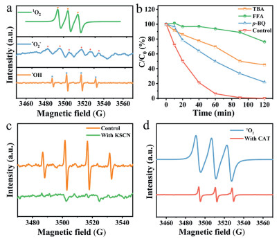
Electron paramagnetic resonance (EPR) spectroscopy was employed to identify reactive species in the CoPc/OCNTs/FeOF HEF system (Fig. 5a). 5, 5-Dimethyl-1-pyrroline N-oxide (DMPO) was used to trap •OH and a quartet of signals was observed, suggesting the formation of •OH. Besides, intense signals from 2, 2, 6, 6-tetramethylpiperidine (TEMP)-trapped singlet oxygen (1O2) and weak signals from DMPO-trapped superoxide radicals (•O2-) were also detected. The •O2- likely originated from the cathodic reduction of O2 through a one-electron transfer process [49]. Quenching experiments were conducted using tert-butanol (TBA), furfuryl alcohol (FFA) and p-benzoquinone (p-BQ) as scavengers for •OH, 1O2 and •O2-, respectively. Fig. 5b demonstrated that the phenol removal efficiencies decreased to 21.9%, 45.1% and 76.2% when FFA, TBA and p-BQ were added, respectively. The results indicated that the 1O2 played a dominant role in the pollutant degradation, followed by •OH, while the •O2- had a minimal impact in the HEF process. The relative contributions of 1O2, •OH, and •O2- to phenol removal were quantified as 53.2%, 31.5% and 15.3%, respectively, based on quenching experiment results and equations (Text S18 in Supporting information). Moreover, testing the CoPc/OCNTs/FeOF cathode in an air atmosphere resulted in a significant reduction in phenol removal rate to 19.3% (k = 0.00157 min-1), highlighting the crucial role of O2 concentration in the HEF performance (Fig. S9 in Supporting information).
Figure 5
Figure 5.
(a) DMPO-•OH, DMPO-methanol-•O2- and TEMP-1O2 signals in EPR spectra. (b) Effects of radical scavengers (TBA, FFA, p-BQ) on phenol removal in CoPc/OCNTs/FeOF HEF system. (c) EPR spectra of DMPO-•OH signal with the addition of KSCN. (d) EPR spectra of TEMP-1O2 signal with the excessive CAT.
To investigate the role of surface Fe(Ⅱ) species in •OH production, potassium thiocyanate (KSCN) was used as a chelating agent to shield the active surface Fe(Ⅱ) sites [50]. As expected in Fig. 5c, the DMPO-•OH signal was nearly undetectable, confirming that •OH primarily originated from the activation of surface Fe(Ⅱ) sites in CoPc/OCNTs/FeOF. The formation of 1O2 was largely dependent on •OH. In addition to the activation of H2O2, O2 could also capture activation energy from the cathode to generate 1O2 [13]. To identify the main pathway for 1O2 generation in the CoPc/OCNTs/FeOF system, excess catalase (CAT) was added to deplete H2O2 and inhibit 1O2 formation through H2O2 activation. As shown in Fig. 5d, TEMP-1O2 signal was significantly reduced at 10 min. This indicated that 1O2 was primarily generated through the generation and activation of H2O2 by CoPc/OCNTs/FeOF, with a minor contribution potentially arising from the direct reduction of O2. Overall, the HEF reaction can be deduced as follows: O2 accepts two electrons from the active sites of CoPc/OCNTs to form H2O2 ((1), (2)). Subsequently, H2O2 is mainly activated by Fe(Ⅱ) of FeOF to form •OH with Fe(Ⅱ) oxidized to Fe(Ⅲ) (Eq. 3). Fe(Ⅱ) is regenerated by H2O2 or by the active site of carbon materials ((4), (5)). •O2- can be produced through one-electron transfer from the electrode (Eq. 6), while •OH further reacts with •O2- and •HO2 to produce 1O2 ((7), (8)) [51]:
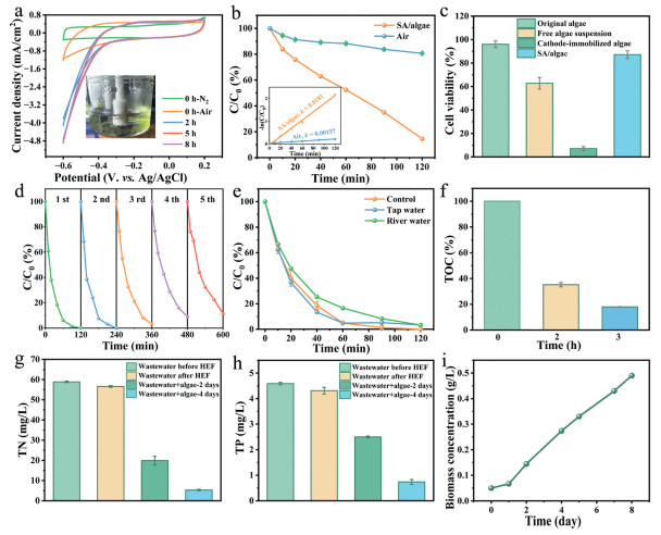
The electrochemical performance of the CoPc/OCNTs/FeOF cathode under SA/algae hydrogel solutions was evaluated. CV analysis revealed a significant increase in current density from 1.14 mA/cm2 to 4.88 mA/cm2 at −0.6 V (vs. Ag/AgCl) after 5 h illumination, stabilizing at 8 h (Fig. 6a). This enhancement demonstrated that sustained photosynthetic oxygen production by the microalgae facilitated the electrochemical reactions. Remarkably, when operated within the SA/algae hydrogel solutions compared to conventional air atmosphere, the CoPc/OCNTs/FeOF system exhibited dramatically improved phenol degradation performance. The removal efficiency increased from 19.3% to 85.4%, while the kinetic rate constant (k) increased from 0.00157 min-1 to 0.0181 min-1, representing an 11.5-fold enhancement in reaction kinetics (Fig. 6b). This substantial improvement highlighted the synergistic effect between the photocatalytic oxygen generation by microalgae and the electrocatalytic activity of CoPc/OCNTs/FeOF HEF system.
Figure 6
Figure 6.
(a) CV measurements of CoPc/OCNTs/FeOF cathode under SA/algae solutions (inset: the photograph of the three-electrode reactor at 5 h). (b) Phenol degradation under air atmosphere or SA/algae solutions (inset: corresponding kinetic fitting curves). (c) Cell viability. (d) Removal rate of phenol in different water qualities. (e) Cyclic tests of CoPc/OCNTs/FeOF HEF system. (f) TOC removal efficiency for phenol wastewater. (g) Residual TN concentrations. (h) Residual TP concentrations. (i) Microalgal biomass dry weight.
The protective effect of alginate encapsulation on microalgae viability was evaluated under HEF conditions (Fig. 6c and Fig. S10 in Supporting information). The original algae showed 96% viability prior to experiments, while free algal suspension showed reduced viability (62.8%), indicating partial cellular damage under HEF conditions. In contrast, SA/algae retained 87.2% viability after 2 h of HEF treatment, indicating effective protection against oxidative stress. Notably, cathode-immobilized algae suffered severe damage, with only 7.2% viability remaining, highlighting the detrimental effects of direct electrode exposure. The results demonstrated that alginate encapsulation protected microalgae from ROS damage while allowing oxygen to diffuse to the cathode.
The CoPc/OCNTs/FeOF cathode exhibited excellent reusability, maintaining 88.5% phenol removal efficiency after five consecutive cycles in Fig. 6d. The structural stability of CoPc/OCNTs/FeOF cathode was characterized post-reaction. TEM images (Figs. S11a and b in Supporting information) showed that the morphology of CoPc/OCNTs/FeOF kept nearly unchanged after 5 reaction cycles. The corresponding XRD patterns (Fig. S11c in Supporting information) retained phase purity consistent with standard FeOF (PDF #70–1522), though with a slightly decreased intensity compared to the pristine cathode. The amount of leaching total iron concentrations after 120 min of reaction was measured bellow 0.78 mg/L (Fig. S12 in Supporting information), lower than the permissible limits set by the European Union regulations (2.0 mg/L) and United States directives (1.3 mg/L) [12]. XPS analysis (Fig. S13 in Supporting information) were conducted on the CoPc/OCNTs/FeOF cathode after the catalytic reaction and the result revealed that the content ratio of Fe2+ and Fe3+ slightly decreased from 1.42 to 1.33, confirming the reusability of the HEF system. To evaluate environmental applicability, phenol degradation was tested in tap water and river water. As shown in Fig. 6e, due to the influence of natural organic matter and inorganic ions, the removal rate of phenol in real river water decreased slightly compared to ultrapure water and tap water, but the removal rate remained at a high level (96.8%).
More importantly, CoPc/OCNTs/FeOF based HEF exhibited outstanding mineralization ability. The total organic carbon (TOC) removal efficiency for phenol simulated wastewater (in river water) was about 82.0% in 3 h (Fig. 6f). Specific energy consumption for pollutants mineralization (SECkg, TOC) was calculated to be 21.9 kWh kg-1 TOC-1 according to the chronoamperometry (i-t) tests (Fig. S14 and Text S19 in Supporting information). The CoPc/OCNTs/FeOF cathode demonstrated superior degradation performance and low energy consumption compared to previously reported catalysts in HEF in the literature (Table S3 in Supporting information). The performance of CoPc/OCNTs/FeOF was further evaluated by treating secondary effluent of urban wastewater with initial TOC value of 32.47 mg/L. The TOC removal efficiency was 50.8% after 3 h (Table S2 in Supporting information), suggesting CoPc/OCNTs/FeOF based HEF was efficient for treating real wastewater. Additionally, actual wastewater typically contains abundant nutrients (e.g., N, P), while the electrochemical Fenton reaction showed limited capability for recovering inorganic nutrients from wastewater [52,53]. Therefore, the removal of total nitrogen (TN) and total dissolved phosphorus (TP) were further investigated and the fate of TN and TP during microalgae culture was presented in Figs. 6g and h and Table S2. In general, TN and TP had minimal elimination in HEF system within 2 h. Whereas, TN was depleted to 5.31 mg/L after 4 days of microalgal cultivation, achieving 90.6% removal efficiency with a removal rate of 12.8 mg L-1 d-1. The concentrations of TP decreased to 0.74 mg/L after 4 days of operation, corresponding to an uptake rate of 0.89 mg L-1 d-1 and a removal efficiency of 82.8%. The microalgae grew well in the treated urban wastewater within 8 days (Fig. 6i). The maximum biomass accumulation reached 0.49 mg/L, with a growth rate of 0.055 g L-1 d-1. The results indicated the Chlorella pyrenoidosa enabled efficient recover N and P nutrients in urban wastewater for carbohydrate production.
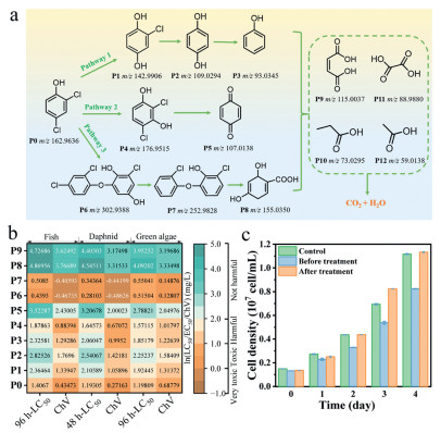
2,4-DCP, one of the phenolic compounds, is regarded as priority pollutants in China and it is much more toxic than phenol and harmful to microalgal cells [54]. Therefore, 2,4-DCP was selected as a model pollutant to explore the degradation pathway and toxicity changes during the CoPc/OCNTs/FeOF HEF reaction. The intermediate products of 2,4-DCP were detected by high-performance liquid chromatography-mass spectrometry (HPLC-MS) in negative ionization mode. Corresponding mass spectra of several intermediate products of 2,4-DCP were shown in Fig. S15 (Supporting information), and the possible oxidation pathways were depicted in Fig. 7a. The whole process primarily includes dechlorination, dehydrogenation, self-coupling, ring opening and mineralization.
Figure 7
Figure 7.
(a) Possible degradation pathways of 2,4-DCP. (b) Toxicity prediction of 2,4-DCP and its intermediates by ECOSAR. Hazardous chemicals could be classified as very toxic (LC50 ≤ 1 mg/L), toxic (1 < LC50 ≤ 10 mg/L), harmful (10 < LC50 ≤ 100 mg/L), or not harmful (LC50 > 100 mg/L) by the Globally Harmonized System of Classification and Labeling of Chemical. (c) Effects of different culture solutions on microalgae growth. Control group: culture medium, culture medium containing 2,4-DCP (40 mg/L) and culture medium containing treated 2,4-DCP.
In pathway 1, 2,4-DCP is attacked by •OH, and the chlorine at 4 positions is displaced by electrophilic hydroxyl groups to produce P1 (m/z 142.99). Then, it can be further oxidated to remove the Cl group to form P2 (m/z 109.03), and subsequently attacked to remove a hydroxyl group to form P3 (m/z 93.03) [55]. In pathway 2, 2,4-DCP is first converted by dehydrogenation to P4 (m/z 176.95) [56], which is further oxidated by dechlorination and hydroxylation into P5 (m/z 107.01) [57]. In pathway 3, 2,4-DCP can undergo a self-coupling reaction and transform to the dimer P6 (m/z 302.94) under the ROS system. Next, P6 and/or 2,4-DCP are further oxygenated for desaturation to form P7 (m/z 252.98) and P8 (m/z 155.04) [58]. Eventually, these intermediates above proceed to the ring opening to generate low molecular weight organic acids, e.g., maleic acid (P9, m/z 115.00), propionic acid (P10, m/z 73.03), oxalic acid (P11, m/z 88.99), and acetic acids (P12, m/z 59.01), which can be ultimately mineralized to H2O and CO2.
To assess the toxicity of 2,4-DCP and its reaction intermediates, we employed the Ecological Structure Activity Relationships (ECOSAR) program to predict the acute and chronic toxicity of these intermediates on fish, daphnia and green algae, as shown in Fig. 7b Compared to the parent 2,4-DCP, the intermediates in pathway 1 and 2 are less toxic to the three aquatic species and the acute toxicity of the late-stage products P5, P8 and P9 decrease to a "harmless" level. In contrast, the degradation products P6 and P7 in pathway 3 are highly toxic to three aquatic species. Fortunately, these two species can be transformed to P8, which poses a lower risk to aquatic environmental safety. To evaluate the detoxification efficiency of 2,4-DCP in CoPc/OCNTs/FeOF HEF system, Chlorella pyrenoidosa was employed as a model organism. The algae were co-cultured with solutions collected before and after treatment, and their growth curves were monitored (Fig. 7c). The results showed that after treatment, the microalgal cell density was slightly higher than that in the control group, while before treatment, 2,4-DCP significantly inhibited cell growth. The finding demonstrated that the treated 2,4-DCP was nontoxic to algal activity and even stimulated cell proliferation. We hypothesized that this growth enhancement resulted from the utilization of small organic acids generated during HEF degradation as additional carbon sources.
In summary, this study developed a bifunctional heterogeneous electro-Fenton catalyst, CoPc/OCNTs/FeOF, that enabled highly efficient pollutant removal under near-neutral pH conditions through simultaneous H2O2 and •OH generation. The CoPc/OCNTs/FeOF delivered high H2O2 production rate of 67.81 mmol L-1 min-1 g-1 and •OH production rate of 136 μmol L-1 min-1 g-1 due to the synergistic effect between CoPc/OCNTs and the FeOF. The CoPc/OCNTs/FeOF HEF system achieved phenol removal with a mass-normalized rate constant of 48.48 min-1 g-1 at pH 6. The system achieved 82% TOC removal efficiency for phenol wastewater with an energy consumption as low as 21.9 kWh kg-1 TOC-1. Notably, the catalyst maintained high degradation activity (> 95% pollutant removal) in tap water and river water, demonstrating robust resistance to complex water matrices. The system's sustainability was further enhanced by integrating alginate-encapsulated microalgae, which provided oxygen in situ for ORR and recovered nutrients (90.6% N and 82.8% P removal via cultivation). Furthermore, the significantly reduced ecotoxicity of 2,4-DCP degradation products was demonstrated by ECOSAR modeling and microalgae growth assays. This work proposes a novel strategy to design a HEF catalyst for cost-efficient and environmentally friendly wastewater treatment by coupling immobilized microalgae.
Declaration of competing interest
The authors declare that they have no known competing financial interests or personal relationships that could have appeared to influence the work reported in this paper.
W. Zhu would like to acknowledge the support from National Natural Science Foundation of China (No. 22176086), the Fundamental Research Funds for the Central Universities (Nos. 021114380222, 021114380214), Research Funds for Jiangsu Distinguished Professor, Carbon Peaking and Carbon Neutrality Technological Innovation Foundation of Jiangsu Province (No. BE2022861), the Research Funds from Frontiers Science Center for Critical Earth Material Cycling of Nanjing University, State Key laboratory of Pollution Control and Resource Reuse.
Supplementary materials
Supplementary material associated with this article can be found, in the online version, at doi:10.1016/j.cclet.2025.112193.
[1]
Preethi, S.P. Shanmugavel, G. Kumar, et al., Environ. Pollut. 341 (2024) 122842. doi: 10.1016/j.envpol.2023.122842
Figure 1
(a) Scheme of preparation of CoPc/OCNTs/FeOF. HRTEM images of (b) CoPc/OCNTs and (c) FeOF (inset: its TEM image; scale bar, 50 nm). (d) CoPc/OCNTs/FeOF and (e) its enlarged image. (f) The STEM image of CoPc/OCNTs/FeOF and its EDS mapping images. (g) XRD patterns of FeOF. (h) Raman spectra. (i) FTIR spectra.
Figure 3
ORR performance of FeOF, CoPc/OCNTs and CoPc/OCNTs/FeOF. (a) CV curves of different catalysts in N2 or O2-saturated 0.1 mol/L Na2SO4 solutions (scan rate: 10 mV/s, pH 6). (b) LSV curves of catalysts obtained on RRDE at 1600 rpm (scan rate: 10 mV/s, pH 6). Solid lines: disk current density; dotted lines: ring current density. (c) H2O2 selectivity and number of transferred electrons (n). (d) H2O2 concentrations produced at −0.4 V (vs. Ag/AgCl) and (g) corresponding Kcat, H2O2 values within 90 min (catalyst loading: 0.5 mg; electrolyte: 15 mL). (e) •OH concentrations at −0.4 V (vs. Ag/AgCl) and (h) corresponding Kcat, •OH values within 90 min. (catalyst loading: 0.5 mg; electrolyte: 15 mL). (f) •OH concentrations produced from the activation of H2O2 in N2-saturated Na2SO4 electrolytes containing 5 mmol/L H2O2 and (i) corresponding Kcat, •OH values within 90 min.
Figure 4
(a) Phenol degradation curves and (b) corresponding k values. Influence of (c) phenol concentration, (d) cathode potential, (e) initial pH and (f) various inorganic ions (each at 5 mmol/L) on the degradation efficiency of CoPc/OCNTs/FeOF. (g) Degradation performance of CoPc/OCNTs/FeOF for various pollutants and (h) corresponding k values. (i) Comparison of CoPc/OCNTs/FeOF cathode and CoPc/OCNTs-FeOF solutions on the degradation of phenol (inset: corresponding k values). Pollutants: 10 mg/L; potential: −0.4 V (vs. Ag/AgCl); catalyst loading: 1 mg/cm2; O2: 100 mL/min; electrolyte: 20 mL, 0.1 mol/L Na2SO4 solution (pH 6).
Figure 5
(a) DMPO-•OH, DMPO-methanol-•O2- and TEMP-1O2 signals in EPR spectra. (b) Effects of radical scavengers (TBA, FFA, p-BQ) on phenol removal in CoPc/OCNTs/FeOF HEF system. (c) EPR spectra of DMPO-•OH signal with the addition of KSCN. (d) EPR spectra of TEMP-1O2 signal with the excessive CAT.
Figure 6
(a) CV measurements of CoPc/OCNTs/FeOF cathode under SA/algae solutions (inset: the photograph of the three-electrode reactor at 5 h). (b) Phenol degradation under air atmosphere or SA/algae solutions (inset: corresponding kinetic fitting curves). (c) Cell viability. (d) Removal rate of phenol in different water qualities. (e) Cyclic tests of CoPc/OCNTs/FeOF HEF system. (f) TOC removal efficiency for phenol wastewater. (g) Residual TN concentrations. (h) Residual TP concentrations. (i) Microalgal biomass dry weight.
Figure 7
(a) Possible degradation pathways of 2,4-DCP. (b) Toxicity prediction of 2,4-DCP and its intermediates by ECOSAR. Hazardous chemicals could be classified as very toxic (LC50 ≤ 1 mg/L), toxic (1 < LC50 ≤ 10 mg/L), harmful (10 < LC50 ≤ 100 mg/L), or not harmful (LC50 > 100 mg/L) by the Globally Harmonized System of Classification and Labeling of Chemical. (c) Effects of different culture solutions on microalgae growth. Control group: culture medium, culture medium containing 2,4-DCP (40 mg/L) and culture medium containing treated 2,4-DCP.

 DownLoad:

 下载:
下载:


 下载:
下载:
