Figure 1.
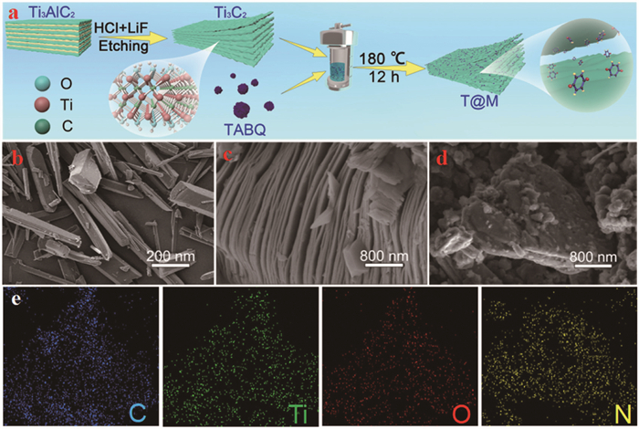
(a) Schematic illustration of the typical preparation procedure of T@M. SEM images of (b) TABQ, (c) Ti3C2, and (d) T@M. (e) Elemental mapping of C, Ti, O, and N of T@M material.
Small molecule quinone-based derivative anchored on Ti3C2Tx MXene framework as a cathode for lithium-organic batteries
Sibo Wang , Xin Xiong , Yun Li , Song Xue , Xueping Zong , Zhiqiang Luo

Lithium organic batteries (LOBs) are promising candidates for high-performance devices due to their advantages of high energy density, low production cost, and environmental friendliness [1-3]. A key challenge for LOBs is developing organic cathodes with high capacity, high electronic conductivity, and high insolubility in organic electrolytes [4-6]. While various quinone-based compounds show potential through quinone framework anchoring [7], polymerization [8], or salt formation [9], the introduction of inactive groups often leads to low practical capacity and reduced reduction potential [10]. Small quinone molecules, such as 1,4-benzoquinone (BQ), offer a high theoretical capacity of 496 mAh/g, an average discharge voltage of 2.7 V vs. Li+/Li, and a corresponding energy density of 1339 Wh/kg (based on BQ mass) [11,12]. However, BQ suffers from severe sublimation and poor electronic conductivity, resulting in rapid capacity decay and sluggish reaction kinetics.
Conductive carbon materials, such as graphene and carbon nanotubes (CNTs) [13-15], are often employed in composite electrodes to mitigate these shortcomings. However, these traditional substrates provide weak π-π physical interactions. Recently, transition metal carbides/nitrides (MXenes), particularly the emerging two-dimensional material Ti3C2Tx MXene, have drawn intense interest for energy-storage applications [16-19]. Their appeal stems from the large surface area, metallic conductivity, robust mechanical strength, and good dispersibility in aqueous and select organic solutions [20,21]. Crucially, the surface functional groups of MXene can interact with organic molecules to form organic-inorganic hybrid structures, influencing the surface electronic structure and enhancing electrochemical properties [22,23]. For example, Talapin et al. demonstrated that hybrid materials can be formed by reacting halogen-terminated MXenes with deprotonated organic amines, combining organic tunability with the superior electron transport of inorganic MXenes [24]. Inspired by this, we propose that such materials could also benefit organic small-molecule cathodes in LOBs.
Herein, we report a novel strategy utilizing 2D Ti3C2Tx MXene as a multifunctional host material to fabricate an MXene-anchored organic cathode for LOBs. In the resulting hybrid architecture, tetraaminobenzoquinone (TABQ) molecules are immobilized between MXene layers via coordination bonds, forming the organic−inorganic hybrid material TABQ@Ti3C2Tx MXene (T@M). This unique structure leverages the MXene layers to provide rapid ion and electron transport pathways while stabilizing the small quinone molecules, which is critical for high-performance electrodes. Consequently, T@M delivers a high capacity of 288 mAh/g at 0.1 A/g and retains 70% of its capacity after 3000 cycles. This excellent electrochemical performance demonstrates that the T@M hybrid material is a highly promising cathode for LOBs.
TABQ was synthesized via two simple steps, which have been illustrated in Supporting information. The corresponding NMR spectra are shown in Figs. S1 and S2 (Supporting information). In addition, the preparation of T@M is schematically illustrated in Fig. 1a. Initially, few-layered Ti3C2Tx MXene was prepared via selective etching of the Ti3AlC2 MAX phase using LiF/HCl [25,26]. Subsequently, the organic molecules of TABQ were anchored onto the surface of the two-dimensional Ti3C2Tx layers through a hydrothermal co-assembly approach. Further details of the synthesis procedure are provided in the Experimental Section (Supporting information). The morphologies of the as-prepared TABQ, Ti3C2Tx MXene, and the T@M hybrid material were characterized by scanning electron microscopy (SEM). As shown in Fig. 1b, the as-synthesized TABQ exhibits a micrometer-scale rod-like morphology, indicating its high crystallinity. Compared with the Ti3AlC2 with typical hierarchical stacking structure (SEM image, Fig. S3 in Supporting information), the Ti3C2Tx MXene showed an accordion-like two-dimensional layer structure after the etching of the Al layers (Fig. 1c). After coordination, the complex of TABQ@Ti3C2Tx showed a rough surface morphology. The few-layer structure coated with some micrometer scale particles for T@M can be detected as shown in Fig. 1d The multilayer structure of MXene was no longer revealed because the TABQ molecules delaminate the MXene layer and further prevent the self-stacking of MXene. Furthermore, the elemental mapping images (Fig. 1e) further indicate the homogeneous distribution of C, Ti, O and N elements in the T@M, suggesting the successfully incorporated TABQ molecules into the layer of Ti3C2Tx.
X-ray diffraction (XRD) was measured to identify the components and structures of the as-prepared materials. As shown in Fig. 2a, the disappearance of the (104) peak at 38.6° and the downshift of the (002) peak from 9.3° to 8.7° in the Ti3C2Tx pattern confirm the successful etching of the Al layers [27]. In addition, TABQ exhibits two sharp crystalline peaks at 2θ ≈ 14°, indicative of its high crystallinity. Upon composite formation (T@M), these peaks are markedly attenuated, revealing that the TABQ lattice is disrupted under high-temperature/pressure conditions and converts into an amorphous structure. When TABQ molecules were anchored on the surface of Ti3C2Tx MXene via Ti···N coordinate bond, the characteristic peaks (002) of Ti3C2Tx MXene further decreases to 6.6°, indicating that the layer spacing of Ti3C2Tx MXene expands to 1.35 nm after the incorporation of TABQ molecules [28]. Consequently, the composite possesses a significantly larger specific surface area (SSA) than pristine MXene. The SSA is an important parameter for evaluating the changes in Ti3C2Tx MXene. Brunauer-Emmet-Teller (BET) result revealed that Ti3C2Tx presents a typical type Ⅲ adsorption/desorption isotherm, while T@M present a type Ⅳ (Fig. 2b). In addition, the SSA of MXene was calculated to be 3.02 cm2/g. After embedding the TABQ, the SSA of T@M is much larger than that of the original Ti3C2Tx, indicating that the addition of TABQ molecules expanded the interlayer spacing of MXene. Fig. 2c depicts the pore size distribution of the Ti3C2Tx MXene prior to and subsequent to the embedding of TABQ. The pore size distribution of MXene materials spans from 4 nm to 13 nm, demonstrating relatively disordered traits. In contrast, the pore size distribution of T@M is concentrated approximately at 3.5 nm, presenting a microporous structure. This outcome also affirmed that the embedding of TABQ, on the one hand, modified the interlayer spacing of MXene, hindering the self-stacking of the material, and on the other hand, enhanced the disordered pore structure of the material, providing a rapid channel for ion transport [29,30].
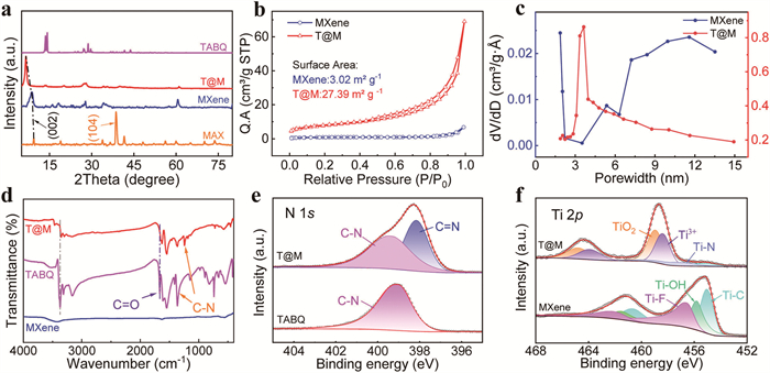
The functional group alterations of MXene before and after TABQ embedding were investigated by various spectroscopies to disclose their interactions. Fig. 2d depicts the Fourier transform infrared spectrometer (FTIR) spectra of MXene, TABQ, and T@M. In the TABQ monomer curve, the characteristic peak located at 1667 cm−1 corresponds to the stretching vibration of C=O bond [31], and the peaks near 3372 cm−1 correspond to the stretching vibration of –NH2 [32]. In comparison, characteristic peak of -NH2 was disappeared for T@M, and the C–N stretch presents obvious blue-shift from 1367 cm−1 (found in the TABQ monomer) to 1253 cm−1. Meanwhile, the strong characteristic peak at 3421 cm−1 attributed to the –OH stretching vibrations of MXene is significantly red-shift in comparison with the hybrid materials T@M. The FTIR results demonstrates the successful synthesis of the T@M composite as well as the coordination connection between MXene and TABQ. Likewise, the Raman spectrum depicted in Fig. S4 (Supporting information) reveals a novel peak at 972.5 cm−1 for T@M, corresponding to the Ti-N bond. This result further substantiates the presence of coordination between the -NH2 group and titanium.
To further investigate the bonding and chemical composition of the samples, we performed X-ray photoelectron spectroscopy (XPS) characterizations. In the wide-scan XPS spectrums (Fig. S5 in Supporting information), the complete disappearance of Al layers in MXene sample and the simultaneous presence of Ti, C, N, and O elements in T@M indicate that TABQ components are successfully incorporated into the etched MXene to become a hybrid composite material of T@M. As shown in Fig. 2e, a comparison of two high-resolution N 1s spectra shows an extra peak at 399.48 eV in T@M, corresponding to the quinoid imine (C=N), along with the benzoid amine (C—N) [32,33]. Fig. 2f presents the high-resolution Ti 2p of both T@M and MXene. In the spectrum of MXene, it can be well deconvoluted into three primary states of Ti-F (456.7 eV), Ti-OH (456.7 eV), and Ti-C (454.9 eV), respectively. It is worth noting that the Ti-F peak disappears, and the intensity of Ti-OH and Ti-C peaks rapidly decreases in the spectrum of T@M, indicating bond cooperation between TABQ and MXene material. More importantly, the fully oxidized TiO2 (459 eV) and Ti3+ (458.4 eV) appear in T@M, implying that MXene can provide a good conductive matrix for organic molecules. TABQ and T@M show the same characteristic peaks of O 1s (Fig. S6 in Supporting information), suggesting a good chemical stability of carbonyl groups during the coordination reaction process. Furthermore, thermogravimetric analysis (TGA) is further conducted to investigate the thermal stabilities for the samples, and the samples can be stable up to 230.5 ℃ with an approximate mass retention of 88% (Fig. S7 in Supporting information), suggesting that the coordination bonds interaction between Ti and -NH2 significantly enhance the stability of the hybrid material. Meanwhile, the loading amount of MXene onto TABQ was calculated to be approximately 30%.
In order to determine the anchoring mode of TABQ in MXene, we utilize the density functional theory (DFT) calculations to investigate the optimal coordination molecular model. As shown in Fig. S8a (Supporting information), the distance between any two nitrogen atoms in TABQ is <5.4 Å, which is significantly smaller than the pore size of MXene (1.02 nm). This suggests that TABQ ligands can only be anchored to the MXene monolayer but cannot bridge adjacent MXene lamellae (Fig. S8b in Supporting information). Meanwhile, the simulations are also conducted to study the stability of the molecular structure with coordinate bond. As shown in Fig. S9 (Supporting information), an amino group initially combines with two nitrogen atoms to form a -NHR structure with a binding energy of −1.26 eV. Upon forming two -NHR structures, the combined binding energy increases to −2.72 eV. After relaxation, the =NR structure exhibits a binding energy of −5.524 eV. These calculations clearly indicate that the imino bonds (=NR) are the most stable among the three structures. DFT calculations further elucidate the coordination of Ti2+ to TABQ in Ti-TABQ. The projected density of states (PDOS, Fig. S9) reveals pronounced overlap between Ti 3d and N 2p orbitals, evidencing robust d–p hybridization.
The redox properties of the T@M cahode material were first investigated using cyclic voltammetry (CV). As shown in Fig. 3a, the second cycle displays two typical redox peaks at 2.18/2.25 V and 2.63/2.97 V, which correspond to the insertion and extraction processes of Li+ in the TABQ molecule (Fig. S10 in Supporting information). The CV curves show highly overlapping redox peaks in subsequent cycles, confirming excellent electrochemical reversibility. Notably, the hydrothermally treated MXene exhibits only a minor pair of redox peaks at 1.68/1.75 V, unequivocally confirming that the primary redox reactions from the TABQ moiety (Fig. S11 in Supporting information). Moreover, the T@M electrode exhibits a negative shift in the oxidation potential and a positive shift in the reduction potential relative to pure TNBQ, which demonstrates reduced polarization in the organic/MXene heterostructure. This difference in CV behavior is a direct consequence of the conductive MXene network and its multifunctional groups, which facilitate Li+ transfer at the interface and thereby improve reaction kinetics. Fig. 3b shows the galvanostatic charge/discharge (GCD) profiles of the T@M cathode at a current density of 0.1 A/g over the voltage range of 1.5–3.5 V. As expected, an inclined linear region is observed, with an average discharge voltage of about 2.5 V, which is consistent with the CV curves (Fig. 3a). It delivers an initial discharge capacity of 299.4 mAh/g and a high reversible capacity of 284.4 mAh/g. It is noteworthy that the high capacity is attributed predominantly to the capacity contribution of TABQ, while the MXene framework plays a secondary role, as evidenced by the negligible capacity of the pure MXene control electrode (Fig. S12 in Supporting information). Fig. 3c depicts the excellent rate capability of T@M cathode. Its reversible capacities reach 316, 280, 225, 188, and 145 mAh/g at the current density from 0.05 to 0.1, 0.2, 0.5 and 1 A/g. Simultaneously, when the rates reverted to 0.5, 0.2, 0.1, and 0.05 A/g, the capacity of the T@M electrode was restored to its original corresponding level. In contrast, the capacities of pristine TABQ are inferior to T@M cathode under the same current density (Fig. S13 in Supporting information). High stable capacities of about 280.0 is maintained at 0.1 A/g for 3000 cycles with circa 100% Coulombic efficiencies in Fig. 3d. In contrast, the cycling behavior of TABQ without MXene delivers a low discharge capacity and poor cycle life. We further evaluated the cycling performance of MXene, we made a comparison between TABQ-carbon nanotube (CNT) and TABQ-MXene, which the later showed stable specific capacity (Fig. S14 in Supporting information). These results demonstrate that the addition of MXene significantly improves the electrical conductivity and insolubility of the TABQ materials (Fig. S15 in Supporting information). Furthermore, the cycled cell was disassembled to retrieve the electrode for SEM inspection. Fig. S16 (Supporting information) unambiguously shows that TABQ did not dissolve into the electrolyte, no bare carbon domains are observed. Consequently, we conclude that the material remains intrinsically stable under operating conditions, and the hybridized heterostructures effectively suppresses the dissolution of organic active species in the electrolyte. Such excellent electrochemical performances are attributed to the anchored coordination bond between the molecule structure of T@M. Electrochemical impedance spectroscopy (EIS) was performed on T@M with different cycles (Fig. 3e). The Nyquist plots showed a semicircle in the high and middle frequency regions and oblique lines in the lower frequency regions, corresponding to the charge-transfer resistance (Rct) and Warburg impedance [34,35], respectively. Compared with TABQ (800.1 Ω), T@M exhibited a smaller Rct of 180.3 Ω (Fig. S17), indicating the improved conductivity in the electrode. Additionally, the Rct value of T@M decreased as the number of cycles increased, implying a gradual activation process of the electrode during cycling.
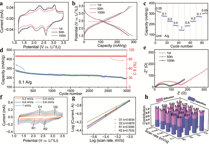
Owing to the excellent cycling performance of T@M, the relative lithium kinetics of the electrode were further measured, as shown in the Fig. 3f. The CV profiles of the T@M electrode revealed two pairs of oxidation peaks (O1and O2) and two pairs of reduction peaks (R1 and R2) at different scan rates from 0.2 mV/s to 1.0 mV/s, respectively. It was observed that the shape of the curve remained the same when the scan rates were raised. The lithium storage mechanism could be revealed in terms of the relationship on the CV profiles between the measured current (i) and the scan rate (v), based on the equations as follows [36,37]:
|
|
(1) |
|
|
(2) |
where v represents the scan rate, i represents the measured current, both a and b (at the range of 0.5–1.0) are constants. Values of b close to 0.5 indicate capacitance-controlled processes, and values close to 1 indicate diffusion-controlled behavior [38,39]. We found that the values of b for each peak were close to 1 in Fig. 3g, indicating that the charge storage process of T@M is preferred to be a capacitance-controlled redox process. Furthermore, the capacitive capacity was further calculated based on the equation [40]:
|
|
(3) |
where i(v) represents the measured current at a fixed potential (v), k1 and k2 are the adjustable constant parameters, v represents the scan rate [41]. As shown in Fig. 3h, the capacitive contribution of the T@M electrode increases markedly with increasing scan rate, indicating a dominant surface reaction mechanism and a copious amount of electrochemically active sites. The MXene provides a conductive network, promotes active sites for lithium reaction, accelerates the electrochemical activity, and enhances the stability of the electrode by coordinate bonds. These factors are jointly contributed to the fast charge transfer ability, high reversible capacity, and superior cyclability of the T@M electrode. Subsequently, the electrical conductivity of TABQ with or without MXene was further investigated by the first principles DFT calculations (Fig. S18 in Supporting information). The calculated energy gap (Eg) between the lowest unoccupied molecular orbital (LUMO) and the highest occupied molecular orbital (HOMO) is 2.95 and 0.78 eV for TABQ and T@M, respectively, indicating that the MXene is beneficial to enhance the electrochemical properties of TABQ.
To elucidate the electrochemical reaction mechanism of the T@M electrode, its structural variation and functional groups evolution were revealed by ex situ XRD, FTIR and XPS spectroscopic analyses. The corresponding samples of T@M cathodes at various charge and discharge states are recorded in Fig. 4a. As shown in Fig. 4b, the (002) diffraction peak at 6.7°, which corresponds to the interlayer spacing of MXene, shifts to lower angles during Li+ intercalation and reversibly returns to its original position upon Li+ extraction. This behavior demonstrates a highly stable and reversible cycling process for T@M electrode. In ex situ FTIR spectroscopy (Fig. 4c), the intensity of the C=O peak at 1634 cm−1 diminishes after discharging. Conversely, this characteristic peak increases as the voltage rises to 3.5 V. Simultaneously, the peak at 1059 cm−1, assigned to C—O-Li, intensifies during discharge and subsequently weakens, suggesting a reversible enolization reaction at the C=O site [41-43].
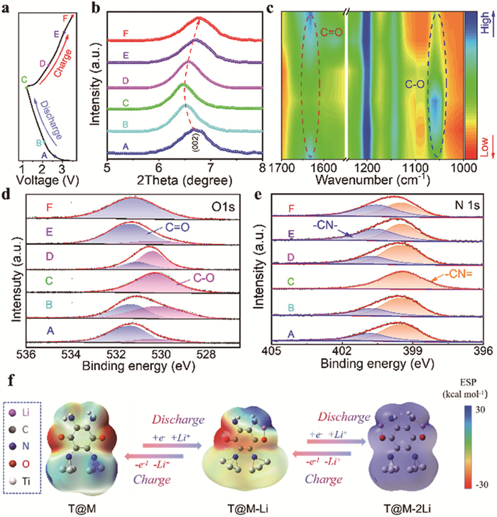
Furthermore, ex situ XPS analysis also provided additional evidence for the reversible Li+ storage mechanism. As shown in Fig. 4d, the O 1s spectra reveal that the C=O peak shifts to a lower binding energy upon lithiation and returns to its original state after delithiation (from A to F), indicating the involvement of C=O groups in reversible redox reactions with Li+. In Fig. 4e, the nitrogen species are observed to evolve from a mixed state (C–N and C=N) to a predominance of C=N, reflecting notable changes in the chemical environment of nitrogen, which are likely associated with charge transfer. In contrast, the Ti spectra of T@M exhibit no significant changes during cycling (Fig. S19 in Supporting information), suggesting that titanium is not an active redox center. Collectively, these XPS results confirm the reversible structural evolution involving both C=O and C–N groups in the cathode material during charge–discharge processes.
To further understand the sequential energy evolution of T@M accompanying multi-electron transfer, we performed DFT calculations to investigate the lithiation mechanism. Two optimized lithium-ion reaction pathways were identified (Fig. S20 in Supporting information). The calculated binding energies (−2.76 and −8.25 eV, respectively) suggest that lithium ions can more readily intercalate and deintercalated in the configuration where they are co-chelated by C=O and -NH₂ moieties. The lithiation mechanism was further elucidated through molecular electrostatic potential (MESP) analysis. As shown in Fig. 4f, the electrostatic potential (ESP) is most negative near the oxygen atom of the C=O group, implying a preferential binding site for lithium ions. Upon lithium-ion binding, the -C-O-Li structure forms preferentially, and the electrostatic potential around the oxygen atom becomes positive.
In conclusion, a quinone-derived small-molecule (TABQ) cathode for LOBs batteries was fabricated by coordinating TABQ to Ti sites on MXene through d–p hybridized coordination bonds, yielding a composite denoted T@M. The composite called T@M allows for facile electron conduction and stable anchoring effect on the MXene matrix. Both of the conjugated benzoid carbonyls and imines of T@M work as the redox centers for insertion and extraction of Li+ via a successive two-step reaction process. It delivers high capacities of about 288 mAh/g at 0.1 A/g with a capacity retention rate of 89.2% after 3000 cycles. This study provides insights into elucidating the charge storage mechanism and enhancing the efficacy of organic batteries.
The authors declare that they have no known competing financial interests or personal relationships that could have appeared to influence the work reported in this paper
Sibo Wang: Writing – original draft, Investigation. Xin Xiong: Formal analysis. Yun Li: Formal analysis. Song Xue: Formal analysis, Data curation. Xueping Zong: Writing – review & editing, Funding acquisition. Zhiqiang Luo: Writing – review & editing, Project administration, Funding acquisition.
We acknowledge the Tianjin Natural Science Foundation (Nos. 23JCYBJC00330 and 24JCYBJC00260) for financial support.
Supplementary material associated with this article can be found, in the online version, at doi:
J. Kim, Y. Kim, J. Yoo, et al., Nat. Rev. Mater. 8 (2022) 54–70. doi: 10.1038/s41578-022-00478-1
Z. Wang, H. Jiang, Y. Zhang, et al., Adv. Funct. Mater. 33 (2023) 2210184. doi: 10.1002/adfm.202210184
L. Li, S. Liu, J. Luo, et al., eScience 5 (2025) 100379. doi: 10.1016/j.esci.2025.100379
Q.M. Xu, Z.X. Liu, Y.C. Jin, et al., Energy Environ. Sci. 17 (2024) 5451–5460. doi: 10.1039/d4ee00520a
Y. Lu, Y. Cai, Q. Zhang, et al., Adv. Mater. 34 (2022) 2104150. doi: 10.1002/adma.202104150
M. Li, R.P. Hicks, Z. Chen, et al., Chem. Rev. 123 (2023) 1712–1773. doi: 10.1021/acs.chemrev.2c00374
Y. Shi, J. Yang, J. Yang, et al., Adv. Funct. Mater. 32 (2022) 2111307. doi: 10.1002/adfm.202111307
Y. Lu, J. Chen, Nat. Rev. Chem. 4 (2020) 127–142. doi: 10.1038/s41570-020-0160-9
H.G. Wang, Q. Li, Q. Wu, et al., Adv. Energy Mater. 11 (2021) 2100381. doi: 10.1002/aenm.202100381
M. Ge, X. Zhou, Y. Qin, et al., Chin. Chem. Lett. 33 (2022) 3894–3898. doi: 10.1016/j.cclet.2021.11.073
J. Yang, H. Su, Z. Wang, et al., ChemSusChem 13 (2020) 2436–2442. doi: 10.1002/cssc.201903227
Z. Song, Y. Qian, T. Zhang, et al., Adv. Sci. 2 (2015) 1500124. doi: 10.1002/advs.201500124
Y. Lu, X. Hou, L. Miao, et al., Angew. Chem. Int. Ed. 58 (2019) 7020–7024. doi: 10.1002/anie.201902185
H. Lyu, C.J. Jafta, I. Popovs, et al., J. Mater. Chem. A 7 (2019) 17888–17895. doi: 10.1039/c9ta04869c
Z. Luo, S. Zheng, S. Zhao, et al., J. Mater. Chem. A 9 (2021) 6131–6138. doi: 10.1039/d0ta12127d
Y. Gao, X. Chen, X. Jin, et al., eScience 4 (2024) 100292. doi: 10.1016/j.esci.2024.100292
J. Qiao, Z. Bao, L. Kong, et al., Chin. Chem. Lett. 34 (2023) 108318. doi: 10.1016/j.cclet.2023.108318
J. Geng, Y. Ni, Z. Zhu, et al., J. Am. Chem. Soc. 145 (2023) 1564–1571. doi: 10.1021/jacs.2c08273
C. Wei, H. Fei, Y. Tian, et al., Chin. Chem. Lett. 31 (2020) 980–983. doi: 10.1016/j.cclet.2019.12.033
J. Xie, X.-F. Cheng, X. Cao, et al., Small 15 (2019) 1903188. doi: 10.1002/smll.201903188
K. Li, J. Yu, Z. Si, et al., Chem. Eng. J. 450 (2022) 138052. doi: 10.1016/j.cej.2022.138052
F. Li, X. Qian, L. Jin, et al., ACS Sustain. Chem. Eng. 9 (2021) 15469–15477. doi: 10.1021/acssuschemeng.1c04636
Y. Luo, J. Liu, L. Zhang, Angew. Chem. Int. Ed. 61 (2022) e202209458. doi: 10.1002/anie.202209458
D. Zhao, Z. Li, D. Xu, et al., Adv. Funct. Mater. 34 (2024) 2316182. doi: 10.1002/adfm.202316182
N. Liu, L. Yu, B. Liu, et al., Adv. Sci. 10 (2023) 2204041. doi: 10.1002/advs.202204041
X. Cao, Z. Yin, H. Zhang, Energy Environ. Sci. 7 (2014) 1850–1865. doi: 10.1039/C4EE00050A
C. Guo, Y. Zhang, M. Yao, et al., ACS Appl. Mater. Interfaces 14 (2022) 29974–29985. doi: 10.1021/acsami.2c08366
S. Kajiyama, L. Szabova, K. Sodeyama, et al., ACS Nano 10 (2016) 3334–3341. doi: 10.1021/acsnano.5b06958
X. Tang, X. Guo, W. Wu, et al., Adv. Energy Mater. 8 (2018) 1801897. doi: 10.1002/aenm.201801897
C. Zhou, D. Wang, F. Lagunas, et al., Nat. Chem. 15 (2023) 1722–1729. doi: 10.1038/s41557-023-01288-w
J. Liu, Y. Yuan, H. Fang, et al., ACS Appl. Energy Mater. 5 (2022) 8112–8122. doi: 10.1021/acsaem.2c00627
K. Fan, J. Li, Y. Xu, et al., J. Am. Chem. Soc. 145 (2023) 12682–12690. doi: 10.1021/jacs.3c02378
L. Wang, Y. Ni, X. Hou, et al., Angew. Chem. Int. Ed. 59 (2020) 22126–22131. doi: 10.1002/anie.202008726
W. Zhang, T. Sun, W. Cheng, et al., Angew. Chem. Int. Ed. 64 (2025) e202505831. doi: 10.1002/anie.202505831
Z. Yu, Z. Gong, Z. Luo, et al., Rare Met. 43 (2024) 6351–6361. doi: 10.1007/s12598-024-02916-1
Z. Yu, L. Huang, Y. Wang, et al., Energy Storage Mater. 66 (2024) 103220. doi: 10.1016/j.ensm.2024.103220
Z. Yu, L. Huang, Z. Sun, et al., J. Power Sources 550 (2022) 232149. doi: 10.1016/j.jpowsour.2022.232149
D.C. Ferreira, J.R. Pires, M.L.A. Temperini, J. Phys. Chem. B 115 (2011) 1368–1375. doi: 10.1021/jp111065m
Y. Wang, X. Wei, Z. Luo, et al., Chem. Eng. J. 518 (2025) 164519. doi: 10.1016/j.cej.2025.164519
Y. Li, J. Zhang, Y. Cheng, et al., Chem. Eng. J. 433 (2022) 134578. doi: 10.1016/j.cej.2022.134578
L. Huang, Z. Yu, L. Wang, et al., J. Energy Chem. 83 (2023) 24–31. doi: 10.1016/j.jechem.2023.04.018
Q. Tang, Z. Luo, H. Yan, et al., Adv. Funct. Mater. 35 (2025) 2502885. doi: 10.1002/adfm.202502885
M. Wu, Y. Zhao, B. Sun, et al., Nano Energy 70 (2020) 104498. doi: 10.1016/j.nanoen.2020.104498

Figure 1 (a) Schematic illustration of the typical preparation procedure of T@M. SEM images of (b) TABQ, (c) Ti3C2, and (d) T@M. (e) Elemental mapping of C, Ti, O, and N of T@M material.

Figure 2 (a) XRD patterns of Ti3AlC2, Ti3C2, T@M, and TABQ. (b) The specific surface area of MXene and T@M. (c) Pore distribution of MXene and T@M. (d) FTIR spectra of MXene, TABQ, and T@M. (e) The high-resolution N 1s spectrum of TABQ and T@M. (f) The high-resolution Ti 2p spectrum of MXene and T@M.

Figure 3 (a) The CV curves of Li-T@M battery at 0.2 mV/s. (b) The charge and discharge curves of Li-T@M battery. (c) Rate capabilities (0.05–1 A/g) of Li-T@M battery. (d) Long-term cycle stability at 0.1 A/g. (e) Nyquist plots of Li-T@M battery. (f) CV curves at different scanning speeds (0.2–1 mV/s). (g) The linear relationship between the oxidation peak current (ip) and the square root (v1/2) of the scanning rate. (h) The contribution rate of capacitance under different scanning speeds.

Figure 4 (a) Discharge and charge profile of T@M at 0.2 A/g in the voltage range of 1.5–3.5 V. (b) Ex situ XRD patterns, (c) FTIR spectra, (d) O 1s and (e) N 1s XPS spectra of T@M electrode in the charging and discharging process, respectively. (f) Optimized configurations of T@M and its intermediate.

 扫一扫看文章

扫一扫关注我们
 DownLoad:
 下载:
下载:
 下载:
下载: