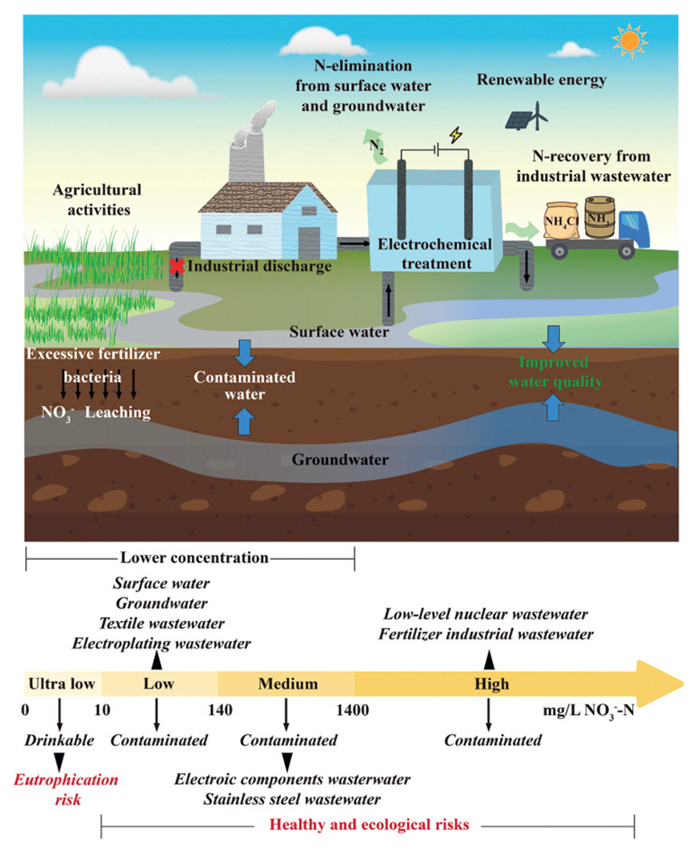
Figure 1.
Concentration ranges of nitrate-containing water samples and their possible treatment directions in practical applications.
Electro-chemical nitrate remediation at lower concentrations: Efforts toward practical environmental applications
Zhe Li , Jun Luo , Li Yao , Yonghai Gan , Zheng Wang , Hongcen Zheng , Minhui Cai , Chengcheng Ding , Xiao Luo , Yibin Cui , Yang Zhou , Wenlei Zhu

Nitrate contamination has become a critical challenge to water safety in countries worldwide [1–4]. The overuse of synthetic fertilizers, discharge of inadequately treated wastewater from industrial activities and municipal sewage, have collaboratively led to progressive accumulation of nitrate in aquatic ecosystems, which triggered imbalance in the nitrogen cycle and caused a series of environmental issues [5]. The World Health Organization (WHO) has recommended restrict criteria for nitrate-N (NO3–-N, 10 mg/L), nitrite-N (NO2–-N, 0.03 mg/L), and ammonium-N (NH4+-N, 0.4 mg/L) in drinking water [6]. Since nitrate exhibits high solubility and strong chemical stability in aquatic environments, achieving effective nitrate removal remains challenging by using conventional co-precipitation and adsorption methods.
Biological denitrification, ion exchange, and reverse osmosis methods have demonstrated efficient nitrate remediation across diverse application scenarios over the past decades. However, each technology has its limitations or potential environmental concerns [7–9]. The biological denitrification method is heavily reliant on external carbon sources to sustain metabolic activity of denitrifying bacteria, which may contribute to secondary pollution in the treated aquatic systems and exacerbate difficulty in treating sludge [10]. With regards to the ion exchange method, the anion exchange resins preferentially adsorb sulfate ions over nitrate ions [11]. Consequently, the adsorption-desorption cycles will be prolonged when nitrate-containing wastewater is coexisting with sulfates to ensure effective removal of nitrates, while additional treatment is also required for the displaced salty waste. For the reverse osmosis system, the high operational and maintenance costs constrain its large-scale implementation, further treatment processes are also necessary for the concentrated brine [12]. Accordingly, recent investigations have focused on the development of efficient and sustainable approaches for nitrate remediation that integrate ecological conservation with source recovery capabilities.
Among emerging technologies, the electrochemical nitrate reduction reaction (eNO3RR) method shows great potential for nitrate remediation through two entirely distinct pathways to produce ammonia (NH3) or nitrogen gas (N2) under ambient conditions [13,14]. The product selectivity, energy-saving attributes, and environmental sustainability of the eNO3RR method make it a disruptive technology, which is expected to be widespread in practical applications. With the deepening of the study, the near-industrial level conversion of nitrate to ammonia has been achieved at high-concentrations (≥0.1 mol/L, 1400 mg/L) [15–19]. Since the underlying mechanisms of eNO3RR have been effectively elucidated, current studies have shifted their focus to the remediation of lower concentration nitrates, to align with the requirements of the practical applications [20]. According to the descriptions in relevant studies (Table S1 in Supporting information), the concentrations of nitrate can be categorized into four ranges (Fig. 1): (1) Ultralow concentration (Cnitrate-N < 10 mg/L), (2) low concentration (10 mg/L ≤ Cnitrate-N < 140 mg/L), (3) medium concentration (140 mg/L ≤ Cnitrate-N < 1400 mg/L), and (4) high concentration (Cnitrate-N ≥ 1400 mg/L).
Theoretically, the eNO3RR undergoes two key processes, including the deoxidation of NOx and hydrogenation of active N-intermediates [12]. In addition to the valence state transitions of nitrogen, both deoxygenation and hydrogenation processes necessitate the involvement of reactive hydrogen species, while the generation of reactive hydrogen species is related to the adsorption and dissociation of H2O on the catalyst surface [19]. However, in the media containing lower concentration nitrates, the mass transfer limitation of nitrate impeded their adsorption and activation, making the hydrogen evolution reaction (HER) the dominant competing process [21]. Even for high concentration nitrates, the nitrate concentration will continuously decrease to a lower level during the electrocatalytic process. Therefore, regulating the surface adsorption of nitrate ions and reactive hydrogen species has become the key role to realize effective nitrate treatment at lower concentrations.
Notably, nitrate-containing wastewater at low concentration levels is more commonly encountered in industrial activities (Table S2 in Supporting information). Beyond the performance differences arising from the above two factors, the practical environmental applications of eNO3RR in these scenarios may also be influenced by multiple interrelated factors, including the coexistence of diverse wastewater constituents, the intrinsic activity of the catalyst, and the characteristics of the reactor system. Hence, the development and selection of suitable eNO3RR strategies should be tailored to the specific demands of distinct application contexts. In this review, recent advances of eNO3RR for treating lower concentration nitrates are summarized and discussed by focusing on their key strategies and underlying mechanisms. Taking into account the specific microenvironment of actual water samples, the challenges in practical applications are also evaluated. We hope this review can offer insights to inspire more substantial initiatives for treating nitrate contaminants at lower concentrations and advancing catalyst design.
eNO3RR can be categorized into direct reduction and indirect autocatalytic pathways based on the nitrate concentration and the acidity of electrolytes. When nitrate concentration is over 1 mol/L, a highly acidic (> 1 mol/ L) environment will promote an indirect nitrate reduction pathway in the presence of nitrite [22]. In this reaction pathway, nitrate does not participate in electron transfer; the system tends to generate NO2 and NO radicals through the Vetter and Schmid mechanisms, thereby promoting the autocatalytic cycle of nitrate [23].
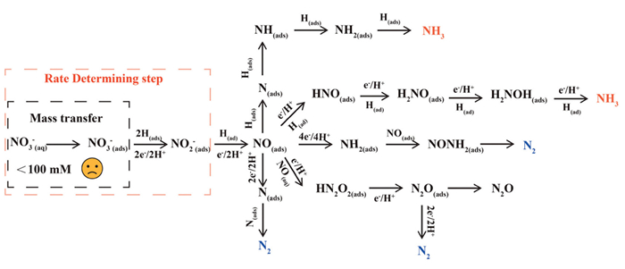
Conversely, when nitrate concentration is lower than 1 mol/L, the eNO3RR process tends to undergo a direct reduction pathway via the electron transfer or the atomic hydrogen pathway (Fig. 2) [12]. Regardless of which of the two mechanisms is involved, the adsorption of nitrate onto the cathode plays a crucial role in determining the rate and selectivity of the following reaction steps [24]. Based on Fick's law, the diffusion rate of nitrate is proportional to its concentration in the solution. At relatively higher concentrations, nitrate ions exhibit improved mass transfer toward the cathode, where the intrinsic reactivity of the active site becomes critical to the reaction rate. However, at low concentrations, the mass transfer limitation of nitrate significantly affects the overall performance of eNO3RR [23]. This is also one of the fundamental reasons why most systems suffer from a decline in performance at the middle-to-late stages of the reaction. Therefore, increasing the localized nitrate concentration on the cathode surface is one of the paramount priorities to address low-concentration nitrate treatment.
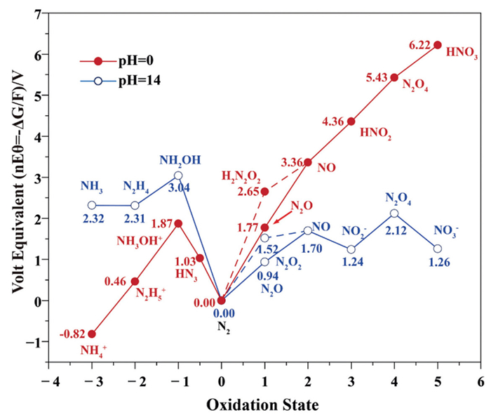
Considering that most eNO3RR systems are operated under neutral or alkaline conditions, NH3 and N2 are identified as major thermodynamic products according to the Frost-Ebsworth diagram (Fig. 3) [23], owing to their high thermodynamic stability among the possible intermediates and end-products [25,26]. Within this pH range, the influence of mass transfer on the thermodynamic stability of the products remains to be further investigated.
The equations for NH3 and N2 generation are listed as follows, where E0 denotes the potential relative to the standard hydrogen electrode (SHE) [26]:
|
|
(1) |
|
|
(2) |
After
The generation of NO(ads) from NO2 (ads)– is another key step, where the subsequent reactions of NO(ads) play a decisive role in directing the product distribution of the electron transfer pathway. Through a successive hydrogenation-coupled electron transfer process, the NO intermediate tends to gradually convert into HNO(ads), H2NO(ads), and H2NOH(ads), eventually forming NH3 as the product. On the other hand, three different pathways have been proposed for generating N2. In pathway Ⅰ, the NO(ads) reacts with desorbed NO(aq), one proton, and one electron to form HN2O2(ads) and further reduces to N2O(ads) and N2. Pathway Ⅱ involves a multi-step hydrogenation from NO(ads) to NH2(ads), where the generated NH2(ads) couples with NO(ads) to form NONH2(ads) that can decompose into N2 [23]. Moreover, the conversion of NO(ads) to N(ads) by proton-electron pairs offers another route to facilitate the N—N coupling process, which requires the simultaneous generation of two N(ads) atoms on adjacent active sites [28].
For the atomic hydrogen pathway, instead of receiving electrons from the electrode, the adsorbed nitrate undergoes a series of hydrogenation steps with H(ads) (produced through the Volmer process) on the electrode surface to generate NO(ads), N(ads), NH(ads), NH2(ads) intermediates. In the presence of H(ads), the generated N(ads) is more likely to react with H(ads) to form N—H bonds, making this pathway favorable for NH3 production [26].
As mentioned earlier, nitrate ions exhibit poor mass transfer capability toward the cathode surface under low concentrations. In the meantime, water dissociation may become the dominant cathodic reaction [29,30]. Once excessive hydrogen occupies the cathode surface, the performance of eNO3RR may be constrained by the competing HER [20]. It is reported that the concentrations between NO(ads) and H(ads) can determine the direction of hydrogenation steps for generating H2, NH3, or N2 [31]. Matching the relative concentration between H(ads) and NO(ads) is conducive to the formation of N2, while the mismatch between the concentration of H(ads) and NO(ads) induces the nitrate-to-ammonia pathway [31]. Therefore, regulating the surface adsorption of nitrate ions and reactive hydrogen species has become the key role to realize effective nitrate treatment at lower concentrations.
The advancement of in-situ characterization techniques has enabled a deeper understanding of the reaction pathways in the eNO3RR process and provided guidance for the further optimization of catalysts. Techniques are allowed for the detection of short-lived intermediates and the observation of dynamic transformations under actual operating conditions.
In-situ FTIR is a powerful tool for the rapid detection of adsorbed intermediates on the surface of catalysts during the catalytic reaction. Through the design and modification of electrolytic cells, the infrared laser can realize a total reflection at the interface of electrolyte, which is referred to as attenuated total reflection-FTIR (ATR-FTIR) [32]. In the eNO3RR process, ATR-FTIR is commonly employed to monitor the evolution of nitrate and nitrogen intermediates (Fig. S1a in Supporting information). It should be noted that the strong absorption band of hydroxyl groups in water can severely interfere with signal detection. Therefore, appropriate adjustments and instrumental optimization are necessary before measurement to minimize such interference.
In-situ Raman spectroscopy is another method for monitoring dynamic changes in catalyst structure, surface adsorbed intermediates, and the redox process of active sites by the frequency difference between inelastically scattered and the incident ray [32]. In comparison with the in-situ FTIR technique, in-situ Raman spectroscopy provides less information on nitrogen-containing intermediates, but it can serve as complementary evidence to support the deduction of the overall reaction pathway (Figs. S1b and c in Supporting information).
By using the DEMS method, the volatile gaseous products can be directly introduced into the mass spectrometer in real time and quantified based on their mass-to-charge ratios (Fig. S1d in Supporting information) [33]. The DEMS device primarily consists of an electrolytic cell, a membrane interface, and a quadrupole mass spectrometer, where the membrane interface is the most critical component of the DEMS system [32]. Volatile gaseous species generated at the electrode surface are required to cross the interface and be transferred into the vacuum chamber of the mass spectrometer under ambient pressure. Since the method is highly sensitive, the volatile intermediates from the eNO3RR system, such as NO (m/z 30), N2O (m/z 44), NH3 (m/z 17), H2 (m/z 2), can be detected by DEMS.
In-situ ESR is generally employed to quantify the existence and changes of H(ads), while 5,5-dimethyl-1-pyrroline N-oxide (DMPO) is always used as a standard trapping agent to extend the lifetime of H(ads). Once H(ads) is produced in the electrocatalytic system, a nine-peak ESR signal could be observed (Fig. S1e in Supporting information) [34]. This would serve as strong evidence in support of the atomic hydrogen pathway.
As shown in Table S3 (Supporting information), the advantages and disadvantages of the in-situ characterization methods are systematically summarized, revealing that no single characterization is sufficient to provide comprehensive insights or rational explanation for certain mechanisms. Therefore, the integration of multiple complementary characterization methods becomes necessary. For instance, Xiao et al. identified the potential intermediates over meso–i-AuCu3@ultra-Au during the electrocatalysis process by using ATR-FTIR spectroscopy. With shifting the applied potential from 0.25 to –0.55 V, the characteristic absorption peaks for NO3 (ads)–, NO2 (ads)–, NO(ads), NH2OH, and NH3 can be observed (Fig. S1a in Supporting information) [21]. According to the in-situ ESR results, H(ads) was effectively generated over meso–i-AuCu3@ultra-Au under 1 mol/L KOH. Nevertheless, through the introduction of 0.5 mol/L nitrate, the ESR signals corresponding to DMPO—H disappeared. This indicates that the eNO3RR system effectively consumes H(ads) during the reaction process (Fig. S1e in Supporting information). At open circuit potential (OCP), in-situ Raman spectra indicate a robust affinity of meso–i-AuCu3@ultra-Au for nitrate adsorption through the characteristic peak of NO3 (ads)– at near 1028 and 1372 cm–1 (Figs. S1b and c). On the other hand, the band at 1200 cm–1 in the time-resolved Raman spectra verified a strong adsorption of NO2 (ads)–, which further demonstrated the considerable performance for eNO3RR over meso–i-AuCu3@ultra-Au. Integrating experimental results with in-situ characterization data, the eNO3RR pathway was identified as: NO3– → NO3 (ads)– → NO2(ads) → NO(ads) → NOH(ads) → NH2OH(ads) → NH3(ads) → NH3.
To achieve high-performance nitrate reduction at lower concentrations, numerous strategies have been performed to improve the localized concentration of NO3–, and to regulate the generation and adsorption characteristics of H(ads). Focusing on the above features, the relevant strategies are categorized into NH3-selective and N2-selective pathways to discuss their advantages in treating nitrate at lower concentrations.
The negative charge of NO3– hinders its localized accumulation on the cathode catalyst surface. By creating positively charged regions on the catalyst surface, effective NO3– enrichment can be achieved via electrostatic attraction.
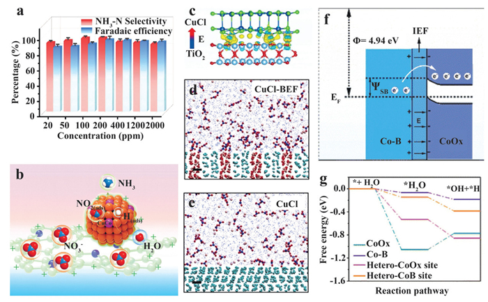
Sheng et al. proposed a CuCo bimetallic nanoparticle/nitrogen-doped carbon composite (CuCo/CN) for a wide range of nitrate conversion (20–2000 mg/L), where the CN matrix is derived from the carbonization of a positively charged 4,4′,4″,4′″-porphine-5,10,15,20-tetrayltetrakis benzoic acid (TCPP, Fig. 4a) [35]. In addition to the nitrate adsorption function given by the positively charged CN matrix, results indicate the incorporation of Co into Cu structure provides optimal sites for H(ads) generation and stabilization. Moreover, the activity of Cu sites is also preserved by regulating the binding strength of intermediates and the proton/electron transfer process (Fig. 4b).
The construction of built-in electric field is typically achieved by integrating two materials with distinct properties, while at least one material is a semiconductor [36]. Through the redistribution of charges at the interface, the Fermi level of two dissimilar materials tends to align and form a built-in electric field in the composite material.
In 2021, Sun et al. created a built-in electric field CuCl catalyst (CuCl-BEF) by linking CuCl with MXene-generated TiO2 through the formation of Cu-O chemical bond (Fig. 4c). With a built-in field strength of 8 × 10⁸ V/m, effective accumulation of K+ and NO3– ions was identified by molecular dynamics simulation at the solid-liquid interface (Figs. 4d and e) [36]. Benefiting from the built-in electric field and high release barrier given by CuCl-BEF, it is difficult for negatively charged NO2– to desorb from the catalyst surface. The electric field also raises the free energy of NO(ads), thus reducing the energy barrier for NO(ads) hydrogenation. Owing to the higher energy barrier for H2 formation on CuCl-BEF, a 98.6% ammonia selectivity was achieved in 100 mg/L NO3– (equal to 22.5 mg/L NO3–-N) with low NO2– production.
Similarly, Zhu et al. developed a Mott-Schottky electrocatalyst by constructing cobalt borides (Co-B)/cobalt oxides (CoOx) heterojunction [37]. The energy level discrepancy between two materials induces the electron transfer from Co-B to CoOx, thus forming an internal electric field in the heterojunction Co-B@CoOx and enhancing NO3– affinity at the Co-B site (Fig. 4f). Moreover, since Co-B barely has the capability to adsorb H2O, the optimal moderation of H2O adsorption capability on the electrophilic CoOx region further avoids the unwanted HER process. Meanwhile, the generated H(ads) is sufficient for the hydrogenation processes (Fig. 4g). As a result, 95% of nitrate can be eliminated from a 100 mg/L NO3–-N solution in 40 min at –0.90 V vs. RHE. Base on similar approaches, Cu1Ni1/NiFeP/Nickelfoam (NF) nanosheet [38], CuO/NiO heterojunction structure [39], CoCuOx@CuOx/copper foam (CF) core-shell catalyst [40], and Cu@CuCoO2 [41] are also performed effective nitrate mass transfer and H(ads) provision, which further verified the application prospects of built-in electric field strategy.
Both of "constructing matrix with positive charges" and "constructing built-in electric field" strategies rely on the formation of positively charged regions to accumulate NO3– through electrostatic attraction. However, their underlying mechanisms diverge significantly. In positively charged matrix, the charges are originated from the functional groups introduced by the precursors, while the matrix themselves does not act as catalytic sites [35]. In contrast, the positively charged regions in built-in electric field are generated from charge redistribution at the interface between two materials with distinct electronic structures. Moreover, the positively charged regions in built-in electric field not only facilitate nitrate accumulation but also can serve as active sites for NO3– deoxidation, thereby participating into the overall eNO3RR pathway [37]. Since NO3– can be effectively transported from positively charged matrix to adjacent catalytic sites, integrating positively charged matrix with optimal built-in electric field materials holds considerable promise for synergistically enhancing both nitrate enrichment and the overall eNO3RR performance.
In comparison with potentiostatic/galvanostatic methods, pulsed potential electrolysis can overcome certain difficulties during the electrocatalytic processes [42]. Therefore, the pulsed potential method has been widely employed in electrocatalysis for hydrogen peroxide production [43], organic synthesis [44], and CO2 reduction [45–47]. During the eNO3RR process, pulsed potential can realize periodic modulation of the local microenvironments at the catalyst's surface. When a positive voltage is applied to the system, NO3– is expected to be accumulated in the Nernst diffusion layer via electro-sorption, which significantly improves the mass transfer capability in nitrate solution with low concentrations. Subsequently, the enriched nitrates will be reduced to desired products after the applied potential is switched to a negative voltage (Fig. 5a).
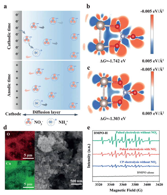
Huang et al. proposed a carbon-supported RuIn3 intermetallic compound (RuIn3/C) as the model catalyst for pulsed electrolysis of nitrate [42]. The results demonstrate that the pulsed potential method can effectively enhance the mass transfer efficiency of nitrates at lower concentrations. In addition to the positive voltage, they found the surface oxidation of low-coordinated indium atoms also provided positive effects on nitrate adsorption over the active Ru0 sites (Figs. 5b and c). By employing cathodic potential of –0.1 V and anodic potential of 0.6 V, higher Faradaic efficiency and NH3 partial current density were obtained by the pulsed system (97.6%, 27.3 mA/cm2) than potentiostatic system (65.8%, 8.9 mA/cm2) in 10 mmol/L nitrate (140 mg/L NO3–-N). To achieve complete removal of nitrate at low concentrations, Liu et al. provided an oxide-derived copper (CuO/Cu2O) as the model catalyst, which can induce redox reactions on Cu foil during the pulsed electrolysis [48]. The Cu foil can generate a rough surface through the dynamic oxidation/reduction of Cu, and provide more active sites for eNO3RR (Fig. 5d). In Raman spectra, the characteristic peak for NO3– appears and gradually increases at +0.2 V vs. RHE, which can be attributed to the accumulation of NO3– near the positively charged cathode. By using quenching agent and electron paramagnetic resonance (EPR) analyses, the authors also proved the existence and the key role of H(ads) in their proposed system (Fig. 5e). Based on the characterization results, they deduced that CuO facilitates the transformation of NO3– to NO2–, while Cu2O tends to produce H(ads) and accelerate the production of NH4+.
Besides the periodic replenishment of NO3– on the cathode surface, the pulsed potential method is capable of preventing the morphology or phase changes of catalysts under long-term cathodic potential and maintaining their intrinsic activities [49]. Consequently, an optimal regulation of applied anodic/cathodic time and voltages is crucial for realizing efficient nitrate conversion in different scenarios [50].
Improving the intrinsic properties of catalysts is a more attractive strategy for achieving effective nitrate remediation at lower concentrations. As the most widely used transition metal in eNO3RR process, Cu has performed capability for NO3– adsorption and conversion (NO3– to NO2–) [51]. However, due to the inferior adsorption of H(ads) on Cu active sites, the further reduction of NO2– was restricted and led to the accumulation of NO2– [52]. Combining the advantages of Cu with other functionalized metal structures is a promising way to overcome their respective drawbacks and improve the overall performance of the hybrid catalyst.
The key strategy to overcome this limiting step lies in reducing the energy barrier for the hydrogenation of nitrogen-oxygen intermediates [53–55]. Theoretically, Cobalt (Co) can effectively realize the hydrogenation process of NO2– to NH3. However, its poor capacity for NO3– adsorption limits the initial deoxidation process of NO3– to NO2–. On the other hand, the intrinsic adsorption capability of Cu species is insufficient to effectively enrich nitrate around the catalyst surface when nitrate is under low-concentration ranges. In this case, studies have emerged in constructing Cu-Co tandem catalysts for NO3– treatment at lower concentrations.
For the Co3O4/CuOx tandem catalyst proposed by Yu et al., metallic Cu was in situ generated during the electrocatalytic process and provided sites to adsorb/activate NO3–. The authors also found that the generated *NO2 on Cu sites will spillover to the Co3O4 site and perform subsequent reactions to form NH3 (Fig. 6a) [53]. As a result, the proposed catalyst performed a 93.77% FE for treating 5 mmol/L NO3–. Meanwhile, the alkaline environment in catholyte also induced an optimal working potential (–0.1 V vs. RHE) for the eNO3RR process (Fig. 6b). Similar synergistic effects are also verified on Cu-CoP [54], Cu@Fe1-NC [55], Cu/Co(OH)2 [15,56], VO-CuCo LDH/SrGO [57], and Cu3Co1-NC catalysts [58]. In addition to build a tandem catalysis system, the introduction of Cu species is also expected to improve the NO3– adsorption/activation activities on their surrounding hetero-atomic sites.
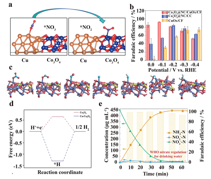
In addition to build a tandem catalysis system, the introduction of Cu species is also expected to improve the NO3– adsorption/activation activities on their surrounding hetero-atomic sites. In 2024, another Cu-Co3O4/nickel foam (NF) catalyst system was proposed by Hu et al. [59]. On Cu-Co3O4 catalyst, the energy barrier for H(ads) formation is deduced to –1.30 eV, which facilitates the eNO3RR process as well as inhibits the unwanted HER at neutral pH (Fig. 6d). Moreover, NO3– is favorable to adsorb and react on Co sites owing to the charge redistribution of Co by the introduction of Cu (Fig. 6c).
For another bimetallic catalyst proposed by Chen et al., the interactions between Ru and Cu favor the adsorption of NO3– on isolated Ru sites. Additionally, the generated *N atom prefers to restrict on Ru sites for further hydrogenation rather than proceed N—N coupling due to the higher reaction energy required for its migration from Ru-Cu to Cu-Cu sites [60]. With a higher NO2– desorption barrier and the inert HER activity on Cu sites, the Ru-CuNW catalyst displayed excellent performance for nitrate-to-ammonia conversion (Fig. 6e). As a result, the proposed system achieved efficient capability for converting nitrate from industrial wastewater level (451.61 mg/L NO3–-N) to a drinkable water level (WHO regulation, < 11.3 mg/L NO3–-N).
The porous structure can provide high surface area, enhanced mass transport, and enrichment effect for NO3–. Building upon this phenomenon, recent studies have demonstrated nitrate enrichment and the subsequent reduction process on the catalysts with porous structures. In 2022, Song et al. proposed a porous Cu@C catalyst for treating nitrate across a wide concentration range (70–1400 mg/L NO3–-N) [61]. By encapsulating Cu nanoparticles (50 nm) into the porous carbon framework (Fig. 7a), the porous Cu@C catalyst exhibits 27.5 times higher NO3– adsorption capacity than Cu nanoparticles, and facilitates the reduction of NO3– to NH3 (Fig. 7b).
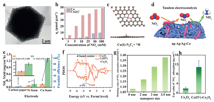
Structure engineering of micro-/mesoporous nitrogen-doped carbon is also feasible to improve the performance for ammonia production in the eNO3RR process. In comparison with the conventional Cu(Ⅱ)-N4 sites, Cu(Ⅰ)-N3C1 has been shown to reduce the activation energy of rate-determining steps (HNO3(ads) → NO2(ads), NH2(ads) → NH3(ads)) [62]. Since H(ads) and NO3(ads) are identified to be adsorbed on the C site and its adjacent Cu(Ⅰ) site with balanced adsorption energies (Fig. 7c), the hydrogenation process for N-species on Cu(Ⅰ)-N3C1 is strengthened, while the competitive HER process and unwanted desorption of intermediates are suppressed.
Beyond matrix engineering, the direct construction of catalysts with a porous structure is another strategy to enhance localized NO3– concentration at the active sites of tandem catalysts. By using a scalable alloying/dealloying method, Feng et al. synthesized a phased-segregated Ag/Ag-Co tandem catalyst with a hierarchical nanoporous structure [63]. In comparison with Ag/Ag-Co nanoparticles, the nanoporous Ag/Ag-Co tandem catalyst demonstrates superior eNO3RR performance, which can be attributed to the NO3– enrichment within nanopores and the accelerated mass transport of reactants and products by the large pores (Fig. 7d). As a result, the cascade catalysis of Ag (NO3– to NO2–) and Ag−Co phases (NO2– to NH3) on nanoporous Ag/Ag-Co tandem catalyst exhibits a 94% NH3 Faradaic efficiency in 10 mmol/L NO3– electrolyte.
Moreover, the inherent porosity of certain materials can also facilitate efficient surface enrichment of NO3–. Kim et al. reported a Cu foam electrode decorated with layered double hydroxides (LDHs) to evaluate the roles in H(ads) production/transportation by varying transition metal combinations in LDHs [64]. In the hybrid catalyst, Cu foam acts as the active site for eNO3RR process, and facilitates the adsorption of NO3– through its highly porous surface and the intrinsic NO3– affinity of Cu species. Meanwhile, LDHs served as an H(ads) supplier for Cu active sites and mitigated the poisoning effect of N-intermediates on Cu sites. With the high kinetic energy barrier for the Volmer reaction (H adsorption) and a rate-determining Heyrovsky reaction (H—H coupling) on Ni3Fe-CO3 LDHs, the composite catalyst exhibits an 8.5-fold higher NH3 yield than that of pristine Cu surface in the presence of 70 mg/L NO3–-N, which further highlights the critical role of H(ads) supplementation at Cu active surface for the eNO3RR process (Fig. 7e).
Oxygen vacancies (OVs) have demonstrated their ability to modulate the electronic structure of catalysts, thereby facilitating the adsorption and activation of reactants [65–67]. The combination of porous structures and oxygen vacancies holds great potential for further enhancing the adsorption capacity of reactants [68]. A Cu foam supported Ce(Ⅳ)-CO3O4 structure was proposed by Zhou et al., where the oxygen vacancies originate from the strong "oxytropism" of Ce(Ⅳ) in CO3O4. In Ce(Ⅳ)-CO3O4, the negatively charged Ov can promote the proton adsorption and lower the energy barrier for the Volmer step through the regulation of the d-band center (Fig. 7f) [69]. Combining the advantages of copious positively charged Ce-Co dual sites and the porous structure for NO3– enrichment (Figs. 7g and h), Ce(Ⅳ)-CO3O4 exhibits high performance in the remediation of practical wastewater over a wide nitrate concentration range.
At the current stage, studies have primarily focused on realizing effective N recovery by converting NO3– to valuable NH3. However, owing to the biological toxicity of NH3, the established water quality standards by China and other countries/authoritative organizations have limited the concentration of NH3-N to 0.5 mg/L in drinking water. Although NH3-N is expected to be completely removed from water by the chlorine disinfection method in waterworks, the rationality for transforming NO3– to NH3 in some scenarios remains debatable. For surface water and groundwater with low-level NO3– contamination, the reduction of NO3– to nitrogen gas (N2) by the electrocatalytic method is regarded as a preferable approach. In eNO3RR process, N2 is typically produced via two distinct pathways: the indirect generation pathway assisted by the addition of chloride ions (Cl–), and the direct generation pathway through the N—N coupling.
Generally, the three-electrode cell for the indirect transformation process is not equipped with an ion-exchange membrane. Two separate steps are involved in the indirect transformation process: the generation of NH4+ on the cathode and the oxidation of Cl– on the anode. By adding optimal concentrations of Cl– to the reaction system, active chlorine species will be generated and will react with NH4+(Eqs. 3–8) [70].
|
|
(3) |
|
|
(4) |
|
|
(5) |
|
|
(6) |
|
|
(7) |
|
|
(8) |
In 2018, Teng et al. proposed an ordered mesoporous carbon (nZVI@OMC) supported nanoscale zero-valent iron catalyst to evaluate the feasibility of the electrocatalytic denitrification process (Fig. 8a) [71]. Reaction parameters, including preparation temperatures, Fe contents (0%−45%), encapsulation effects, and the concentration of NO3– (3.29–32.9 mg/L NO3–-N) have been systematically investigated to reveal the conversion mechanism from NO3– to N2 in the presence of Cl–. The author inferred that H2 and Cl2 were produced at the cathode and anode, respectively. Benefiting from the advantages of large surface area, pore volume, and good conductivity of OMC, the encapsulated Fe(0) sites are inclined to maintain activity and react with NO3– and other N intermediates with the assistance of in-situ generated H2. Furthermore, the produced NH4+ undergoes an oxidation process to yield N2, in accordance with Eq. 6. However, the N2 selectivity is limited to 74% even in the presence of Cl–, suggesting that the nZVI@OMC catalyst has unsatisfactory electrocatalytic performance in NH4+ generation. Nonetheless, this work represents a successful attempt at the electrocatalytic NO3–-to-N2 pathway and provides valuable guidance for the research in this field.
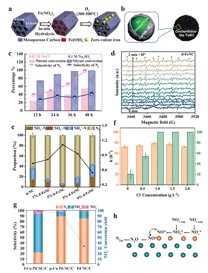
Su et al. hypothesized that increasing the dispersion and loading of iron nanoparticles within a carbon framework could further promote the efficiency of the electrochemical denitrification process [72]. By fabricating CL-Fe@C microspheres with ~74% Fe content, they declared a ~98% N2 selectivity and ~100% nitrate removal rate can be obtained (Fig. 8b). Although a higher N2 selectivity is observed in the presence of Cl–, the nitrate conversion capability is restricted (Fig. 8c). In 2024, Ma et al. proposed another Fe-doped porous catalyst named iron-doped zeolite imidazolium framework derived defective nitrogen-doped carbon (d-FeNC) to investigate the effect of ZIFs-derived porous nitrogen-doped carbon substrates on the electrocatalytic denitrification process [73]. In addition to optimizing the denitrification efficiency by adjusting basic parameters, the authors also investigated the generation and roles of H(ads) on the denitrification process by using in situ ESR analysis and chemical trapping agents (Fig. 8d). The results indicate H(ads) can be effectively generated and stored on the defective CN structure, which facilitates the NO2–-to-NH4+ pathway in the reduction process. By introducing Cl– into the electrolyte, a 97% NO3–-N removal and nearly 100% N2 selectivity are achieved by d-FeNC (3% Fe loading, Fig. 8e). Furthermore, the indirect pathway has been verified by utilizing multiple cathode catalysts, including self-supported Cu/CuO microspheres on Ni foam (Cu/CuOms/NF) [74], cubic Cu2O film with predominant (111) orientation [75], amorphous Cu0 nanorods [76], boron-iron nanochains (B-Fe NCs) [77], and Ni foam/CNTs/Cu composite electrode [78].
As previously mentioned, the indirect process involves the oxidation of Cl– to Cl2, which makes the anode reaction another crucial factor to influence the overall efficiency of the electrocatalytic NO3–to-N2 pathway. Based on the various issues encountered in using carbon nanotubes as the anode at the current stage, Zheng et al. developed titanium suboxides (TiSO) functionalized CNTs to extend the electrochemical window of CNTs and promote HClO generation for the oxidation of NH4+[79]. As a result, a 99.0% N2 selectivity is achieved by employing TiSO—CNT as the anode catalyst, whereas the Pt and pristine CNT anodes only exhibit 5.2% and 64.6% N2 selectivity, respectively.
In addition to the activity of the anode and cathode, the nitrate removal efficiency is also influenced by the concentration of Cl–. As investigated by Duan et al., the selectivity of N2 in their reaction system is gradually increased to 100% with the addition of Cl– from 0 to 2 g/L (Fig. 8f) [70]. Nevertheless, once the concentration of Cl– exceeds a certain threshold, a decline in the nitrate removal proportion will be induced by the side reaction between ClO– and NO2– (Eq. 8).
Since the chlorination process may induce the formation of harmful chlorinated by-products (e.g., per- and polyfluoroalkyl substances, PFAS) [80], the direct reduction process without the addition of Cl– is more eligible for nitrate management to ensure the security in some practical scenarios. Generally, the direct generation of N2 requires the dimerization step through the coupling of two N-intermediates, which were generated and adsorbed on adjacent active sites [81].
In previous studies, platinum group metals (Pt, Pd) were considered as efficient materials for N2 generation and inhibition of unwanted site poisoning caused by the excessive accumulation of N-intermediates [82,83]. Although Pd has intrinsic limitations in converting nitrate to nitrite, combining Pd with secondary promoter metals (Cu, Sn, In) is identified to be an efficient way to improve the overall performance for N2 generation [84]. To evaluate the roles of Pd and the promoter metal Cu in Pd-Cu bimetal catalysts, Lim et al. developed a Pd NC catalyst with tunable copper surface coverage [85]. By comparing the product distribution among the bare PdNC, partial Cu coated (p-Cu PdNC), and fully Cu coated PdNC (f-Cu PdNC), the authors deduced that Cu(100) is selective to ammonium production, while Pd(100) contributes to N2 production (Fig. 8g). In the p-Cu PdNC catalyst, NO3– prefers to be adsorbed onto Cu(100) domains and further reduced to *NO intermediate. Since the *NO adsorption energy on the Pd (100) surface is more exergonic than that on the Cu(100) surface, *NO tends to migrate to adjacent Pd(100) domains and is selectively converted to N2 through the N—N coupling between *N (from *NOH) and *NO (Fig. 8h).
However, the practical implementation of platinum group metals is hindered by two major limitations: (1) The significantly increased catalyst costs for using noble metals, and (2) undesirable byproducts (especially nitrite and ammonium) are inevitably generated during the reaction process, making N2 unavailable to achieve ~100% selectivity.
Generally, the cost of an element is determined by its crustal abundance and the complexity of its purification process. In this case, promising earth-abundant alternative elements for electrocatalytic nitrate reduction were investigated by quantifying their NO3– degradation rates and evaluating their selectivity for NO2–, NH4+, and N2 in 100 mg/L NO3–-N [86]. By considering the electron configurations of candidate elements, the authors selected first-row transition metals (e.g., Ti, Fe, Co, Ni, Cu, Zn), carbon, and tin (Sn) materials as the model catalysts. As a result, the Sn-based and boron-doped diamond electrodes show considerable N2 selectivity and nitrate degradation rates compared to the selected first row transition metals, which preliminarily validates the feasibility of earth-abundant elements in treating nitrate to N2.
In addition to element selection, macro structure, and crystal engineering, rational design of the reaction system is also crucial to achieve high N2 selectivity in the electrocatalytic denitrification process. For the conventional flow-cell, the flow-by mode fails to accumulate nitrate near the electrode due to mass transfer limitations, especially under ultra-low nitrate concentrations. To overcome this limitation, Wang and Wu et al. developed carbon nanotube (CNT) electrified membranes (EMs) incorporated with catalysts (Cu1NC and N-doped carbon black supported Sn catalyst) to achieve a permeate flow-through mode, thus improving mass transfer and the reaction kinetics of the eNO3RR process [31,87]. The CNT interwoven framework provides high conductivity, water permeability, and flexibility for the free-standing EM, which facilitates direct contact between nitrate ions and the active sites of incorporated catalysts to enhance the reaction rate and N2 selectivity (Figs. 9a and b). However, due to the inherent limitations of the proposed catalysts, achieving nearly 100% N2 selectivity remains challenging in the absence of additional chloride ions in the reaction system. Nonetheless, EMs are expected to provide additional electrochemical features for traditional membrane technologies, which may benefit the development of next-generation membrane technology/equipment for nitrate remediation at low concentrations.

For practical applications, the selection of indirect or direct pathway should be guided by the specific characteristics of the treatment scenario to ensure the rationality of the strategy. From the perspective of actual water environments, the indirect generation pathway is particularly suitable for wastewater containing a certain concentration of chloride ions, such as effluents from the fertilizer industry and municipal sewage [88,89]. In the case of nitrate polluted freshwater and groundwater that may serve as potential drinking water sources, as well as other scenarios requiring strict effluent quality standards, the direct generation pathway represents the more appropriate option.
In the context of electrochemical nitrate remediation, both NH3-selective and N2-selective pathways are of significant practical importance, each offering distinct advantages and potential application scenarios. As discussed above, an increasing number of catalysts and strategies have emerged for the treatment of nitrate at lower concentrations. Under this premise, it is necessary to evaluate the scalability and feasibility of these techniques in treating real wastewater. In this section, the practical applicability and technical challenges for electrochemical methods across four concentration ranges were further evaluated.
High or medium concentrations of nitrate are commonly found in fertilizer industry wastewater [88], low-level nuclear wastewater [90], and stainless steel wastewater [91]. Under these conditions, the NH3-selective pathway offers greater economic viability than the N2-selective pathway. However, it is important to carefully assess the cost-benefit balance in practical systems. In addition to achieving high NH3 yields, the further development of technologies for NO3– collection, NH3 separation, purification, and compression is essential to reduce the financial burden of NH3 recovery from wastewater.
The air stripping method is recognized as an efficient physical process for separating and recovering ammonia from ammonia-rich streams. Under alkaline conditions (10.8–11.5), NH4+ will react with hydroxide ions to produce NH3. With the continuous generation of NH3 in the eNO3RR system, the high vapor pressure of NH3 in the liquid phase promotes the migration of NH3 to the gas phase to equilibrate the saturated vapor pressure of ammonia at the gas/liquid interface. Air stripping can disrupt this equilibrium and separate NH3 from aqueous solution with high efficiency. Benefiting from these characteristics, the air stripping method has been successfully implemented in multiple application scenarios.
For instance, Chen et al. demonstrated that over 99.7% of the NH3 could be stripped from the effluent stream and subsequently collected via acid trap or cold condensation (Fig. 9c) [60]. In practical scenarios for wastewater treatment, the operation of this method is relatively simple and would not be affected by wastewater fluctuation and toxic loads [92]. One potential concern is the formation of calcium carbonate under alkaline conditions, which often leads to unwanted fouling in the packed beds. Moreover, in scale-up applications for ammonia recovery from eNO3RR systems, the floor space of packed towers and the techno-economic aspects still require further investigation and optimization. On the other hand, given that most of the ammonia from the Haber-Bosch process is utilized for synthesizing nitric acid, which in turn serves as the feedstock for nitrate synthesis, the direct nitrate separation and purification process from high-concentration nitrate-containing wastewater (e.g., fertilizer industrial wastewater, low-level nuclear wastewater) is also a rational strategy.
In a representative case for eNO3RR, Zhang et al. performed a systematic techno-economic assessments (TEA) of their proposed system [93]. According to the reported model [94], the cost of nitrate-containing wastewater treatment was comprehensively evaluated from multiple perspectives, including electrolyzer cost, balance of plant cost, electricity cost, maintenance cost, water cost, electrolyte cost, air stripping cost, materials cost, and electrodialysis cost (for concentrating nitrate). The results indicated that when the electricity price is $0.03/kWh (target announced by United States department of energy), the treatment cost of nitrate-containing wastewater is approximately $3.15 per kg N (Fig. S2 in Supporting information). In comparison with the treatment costs of $15.56 per kg N for the nitrification/denitrification process [95] and $14.60 per kg N for ion exchange [96], the well-established eNO3RR method offers a low-cost and efficient approach for the remediation of nitrate containing wastewater, while simultaneously enabling ammonia recovery as a value-added product. With the continuous advancement of renewable energy technologies, the associated decline in electricity prices is expected to further strengthen the economic competitiveness of eNO3RR.
Low concentration nitrate is commonly present in polluted surface water, groundwater [97], municipal wastewater [98], electroplating wastewater [51], Integrated circuit packaging wastewater [99], and textile wastewater [6]. The nitrate concentration in contaminated groundwater and surface water is close to the permissible limit of environmental quality standards. Consequently, although an efficient NH3-selective pathway can be achieved under these concentrations, the separation and recovery of NH3 at low concentrations would impose substantial cost burdens. Since groundwater and surface water are commonly used as drinking water sources, converting NO3– contaminants into environmentally benign N2 aligns with ensuring water safety in such scenarios. As a critical chemical additive, ammonia solution is employed in textile and electroplating industries to improve the mechanical properties of cotton textiles and the quality of electro-deposited layers, respectively [100,101]. In this case, nitrates in electroplating and textile wastewater may have the possibility for recovery and reuse in the form of ammonia.
The ultralow nitrate concentration falls within the safety limits set by WHO (Cnitrate-N < 11.3 mg/L) and China's national (Cnitrate-N < 10 mg/L) drinking water standards, which generally do not need further treatment for nitrate removal. However, nitrate can trigger unwanted eutrophication in aquatic systems even when the NO3–-N is as low as 2 mg/L [31]. Accordingly, in practical applications, the necessity for further nitrate treatment should be determined based on the functional classification of the water body. Under ultra-low nitrate concentrations, the N2-selective pathway is recommended to prevent secondary pollution of water bodies caused by ammonia.
Besides the NH3-selective and N2-selective pathways, innovative strategies are also expected to provide new insights into the treatment of nitrate-contaminated water samples. For instance, electrocatalytic C—N coupling has demonstrated its capability to produce diverse organonitrogen compounds by the co-reduction of CO2 and nitrogen species [102–106]. By integrating CO2 fixation with nitrate utilization, this strategy offers a promising alternative for nitrogen recovery from nitrate-contaminated wastewater. Meanwhile, the strategic integration of C—N coupling with the carbon capture, utilization, and storage (CCUS) technology could also provide carbon mitigation functionalities for the industrial activities that simultaneously emit nitrate and carbon dioxide [107]. However, considering the inherent toxicity and aqueous solubility of organonitrogen compounds, the C—N coupling strategy is not suitable for treating contaminated surface water or groundwater. So far, the studies on the electrocatalytic C—N coupling process remain at an early stage. The rational design of catalysts is urgently needed to improve the selectivity and reaction rates toward target organonitrogen compounds.
Taking urea synthesis as an example, Luo et al. reported a 3D Zn/Cu hybrid catalyst which have the capability for relay catalysis [108]. They found the key intermediate *CO2NO2 for C—N coupling preferentially formed on Zn sites, while the protonation steps occurred on the adjacent Cu sites. As a result, a 75% FEurea was achieved at 1000 ppm NO3–-N (wastewater concentration level). However, this system still suffers from relatively low current density under optimal working potentials, leading to an unsatisfactory overall urea yield (60 mmol h–1 gcat–1). Catalyst surface engineering has been demonstrated to further enhance urea yield and the stability of the catalyst. By incorporating amino ligand into copper phthalocyanine (CuPc), Li et al. optimized the electronic structure of CuPc-amino, which enabled more efficient adsorption and activation of CO2/NO3– and their intermediates [109]. Moreover, the amino substitution also strengthened the binding energy between Cu and N atoms in CuPc-amino, thus suppressing the electrochemically induced demetallation during the reaction process. Consequently, a 103.1 ± 5.3 mmol h–1 gcat–1 yield rate can be achieved in their proposed system. Despite the fact that the proposed system requires a relatively negative working potential (–1.6 V vs. RHE) and suffers from limited Faradaic efficiency (11.9% ± 0.6%), it provides a rational design concept that may guide the development of catalysts for urea synthesis in future studies. In addition to catalyst engineering, regulating the local reaction environment has also been recognized as an effective strategy to optimize the selectivity and activity of the C—N coupling process. Building on this concept, Hu et al. utilized pulsed potential electrolysis strategy for electrochemical urea synthesis [110]. They found the pulsed potential electrolysis can modulate transient mass transport dynamics and adjust the local pH of active sites, thereby suppressing by-product generation and enriching the coverage of C/N intermediates. In addition, they further validated the universality of pulsed potential electrolysis by employing it to previously reported ZnO and PdCu catalysts for urea synthesis. In comparison with conventional potentiostatic strategies, pulsed potential electrolysis demonstrates a remarkable reduction in energy consumption, thereby offering enhanced prospects for scalable applications.
In addition to urea, methylamine can also be synthesized through the electrocatalytic C—N coupling between CO2 and nitrate. Wu et al. proposed a cobalt β-tetraaminophthalocyanine (CoPc-NH2), which demonstrated the capability to simultaneously catalyze the reduction of CO2 and NO3– [105]. The generated HCHO and NH2OH intermediates tend to undergo a coupling process to form formaldoxime, which serves as the key intermediate for generating methylamine. The proposed system pioneered the direct electrosynthesis of methylamine by using CO2 and NO3–. However, competing reactions at the single active site hinder the concurrent formation of key intermediates, resulting in a Faradaic efficiency of only 13% for methylamine production.
The electrochemical synthesis of glycine is another way to realize nitrogen source recovery. By using oxalic acid as the carbon source, glyoxylic acid can be generated in acidic media and subsequently attacked by the NH2OH intermediate to form glyoxylic oxime [111]. To avoid competitive HER under highly acidic conditions, Kim et al. fabricated a Cu-Hg alloy electrode to enlarge the overpotential of HER. As a result, a FE of 43.1% for glycine was achieved with a current density up to 90 mA/cm2. Although a relatively high nitrate concentration (0.25 mol/L) is employed in this system, this method may serve as a potential strategy for nitrogen recovery from acidic wastewater under practical conditions.
It is worth noting that the vast majority of published studies are focused on demonstrating their catalysts or technologies under ideal conditions, namely, conducting lab-scale electrocatalytic reactions utilizing prepared nitrate-containing electrolytes with controlled concentrations. There is no doubt that these catalysts or technologies have demonstrated impressive conversion performance under ideal reaction conditions. However, once wastewater from practical scenarios is introduced into the reaction system, the conversion performance often declines due to the complex microenvironment in practical wastewater. Beyond the essential techno-economic assessments, several challenges still need to be addressed before the electrochemical nitrate remediation technologies can be applied in real-world scenarios.
For further applications of the eNO3RR strategy, the types, selectivity, and controllability of byproducts are pivotal factors determining its safety, environmental compatibility, and industrial viability. Firstly, the HER is the dominant competing pathway due to its intrinsic kinetic advantages under low nitrate concentrations. This competition will significantly undermine the electron utilization efficiency of the eNO3RR system. In addition, variations in the micro-environment of the active surface may trigger the generation of unwanted nitrogenous byproducts, thereby altering the product distribution. The excessive generation of H2 also introduces safety concerns in scaled-up systems, leading to increased maintenance costs. Viewed from the standpoint of environmental applications, the byproducts including NO2–, NH2OH, NO, and N2O act as secondary pollutants, posing risks to both aquatic and atmospheric systems. Moreover, the uncontrollable formation of these byproducts implies additional separation burdens, critically undermining the industrial viability. Accordingly, when designing eNO3RR systems for treating real-world low-concentration nitrate wastewater, a comprehensive consideration of catalyst design, electrolyzer modification, and the complex constituents of practical wastewater is strongly warranted.
The rational design of catalysts is crucial for the efficient removal and recovery of low-concentration nitrates. Further modification and optimization of the catalyst structure should be conducted under specific environmental conditions to meet the requirements of practical applications [112]. To this end, strategies like d-orbital electronic configuration modulation [113], coordination shell modification [114,115], interfacial polarization [34], intra-particle atomic arrangement modification, and spillover effects modification [116] from other electrocatalytic systems may offer valuable guidance.
Although most of the aforementioned studies do not have a direct connection with eNO3RR, these strategies still provide valuable insights that can be adapted to advance this field. As discussed above, regulating the adsorption of reactants and intermediates represents a common challenge encountered in most reaction systems. A deep understanding of the interactions between active sites and nitrate or nitrogen-containing intermediates is crucial for the rational modulation of catalyst properties and overall reaction performance.
Innovative technologies can be utilized to gain a thorough comprehension of these key parameters. In comparison with the conventional trial-and-error method and DFT calculations, the machine learning method provides a fast and efficient approach for multidimensional catalyst screening. Through the model training, material screening, experimental verification, and DFT calculations, numerous studies have demonstrated the feasibility of machine learning methods in designing optimal catalysts for specific application scenarios [117–119]. With the assistance of improved algorithms and high-throughput experimentation, ML is expected to be trained on practical wastewater models and provide reliable predictions for low-concentration nitrates treatment [120]. This necessitates a collaborative effort within the community to construct accurate and high-quality databases that can enhance the universality of machine learning models for catalyst design [121].
Advancing electrolyzer design is also essential for enabling eNO3RR to address practical environmental challenges. It is worth noting that most strategies for low-concentration nitrate remediation in the above sections have employed H-type cells as the electrolyzers, where the two-chamber configuration facilitates precise control over reaction conditions, thereby enabling more effective elucidation of the reaction mechanism. However, the mass transport limitation issue in H-cell makes it unsuitable for scale-up and continuous operation (Fig. S3a in Supporting information) [8]. Serving as a more viable solution, flow cells can effectively improve the performance of eNO3RR by offering enhanced mass transfer characteristics at the solid-liquid interface [122]. Given the high toxicity of ammonia, its direct release from the electrolyzer raises environmental concerns, thus hindering the practical applicability of such systems in environmental remediation. Therefore, real-time collection of the produced ammonia is critical for minimizing environmental impact and enhancing the sustainability of nitrate electroreduction systems. Mi et al. designed a "two-in-one" flow cell for eNO3RR and simultaneous ammonia capture. The two chambers were separated by a gas diffusion electrode (GDE, Fig. S3b in Supporting information) [123]. Unlike conventional flow cells, sulfuric acid was introduced into the opposite chamber of the "two-in-one" flow cell. Accordingly, most of the in-situ generated ammonia molecules tend to diffuse across the GDE, where they are subsequently trapped by sulfuric acid to form ammonium sulfate. By connecting the two chambers with an external gas tube, the overflowed ammonia gas can also be captured. Among flow cell configurations, the flow-through reaction mode can further enhance mass transfer while effectively mitigating catalyst degradation and deactivation during continuous operation [33,85]. Zhou et al. found that inter-electrode distance significantly affects the selectivity of reaction products under the flow-through reaction mode, where the 0.1 mm inter-electrode distance (zero-gap electrochemical reactor) favored N2 generation without the addition of external chloride ions (Fig. S3c in Supporting information) [124]. In-situ electrochemical characterizations revealed that the conversion of NO(ads) to N(ads), as well as N—N coupling, exhibited higher selectivity in the zero-gap electrochemical reactor, thereby promoting efficient N2 production. Once the pressure buildup issues caused by channel clogging and confined flow-through spaces are resolved, the zero-gap electrochemical reactor could serve as an effective route for nitrate-to-nitrogen conversion. Moreover, owing to the low ohmic resistance, high mass transfer efficiency, and high energy efficiency, the membrane electrode assembly (MEA) configuration holds great potential for industrial-scale applications (Fig. S3d in Supporting information) [125,126]. Although the MEA configuration is also referred to as a zero-gap cell, the anolyte and catholyte in the MEA system operate in a flow-by mode during the reaction. Through continuous advancements in cathode catalyst design, impressive eNO3RR performance has been achieved in MEA electrolyzers, thereby offering great potential for practical applications [93,127]. Technical parameters of aforementioned works are listed in Table S4. It can be observed that these technologies are capable of achieving nearly 100% nitrate removal efficiency along with a long-term stability for over 100 h. In terms of energy consumption, the zero-gap electrochemical reactor proposed by Zhou et al. exhibits a higher energy demand per kilogram of nitrogen removed, primarily due to its low-concentration nitrate application contexts [124]. Nevertheless, the efficient conversion of nitrate into dinitrogen endows flow-through reactors with greater environmental significance for treating natural surface and groundwater. For the flow cell and MEA configuration, the relatively lower energy consumption makes these systems more attractive for nitrate-to-ammonia conversion, thereby generating certain economic value [93,123,127]. Accordingly, the development of these reactors is expected to diversify technological pathways and expand practical solutions for the treatment of nitrate-containing wastewater in future applications.
To reduce the ionic resistance in electrocatalytic systems, high concentrations of salts are typically added to the electrolyte along with nitrate to prepare electrolytes. In practical applications, apart from the industrial wastewater and contaminated Salt Lake water, the salt concentration in surface and ground water rarely meets the conditions proposed in reported systems. It is impractical to add additional salts to surface water and groundwater that are already contaminated, as it would significantly increase salinity levels and threaten the existing aquatic ecosystem. Therefore, an optimized electrolyte is required to enhance the feasibility of eNO3RR system for the practical implementation. For instance, Chen et al. recently reported a porous solid electrolyte (PSE) reactor to promote eNO3RR performance, thus eliminating the need for recovery of high-salinity electrolytes (Figs. S3e and f) [128]. Unlike traditional membrane electrode assemblies (MEAs), the PSE reactor incorporates two cation exchange membranes. Moreover, an extra layer of polymer-based porous solid ion conductors is capable of preventing the HER reaction by tuning the ion flux through the CEM on the cathode side. With the assistance of the air stripping method, the generated NH3 can be removed from the alkaline Na+stream, while the remaining Na+stream is recirculated to the PSE layer to continuously supply Na+ across the cation exchange membrane (CEM) and maintain the ionic balance of the cathode chamber. This innovative approach enabled the electrocatalytic nitrate removal in an electrolyte solution-free system. In addition to its applications in N-recovery from industrial nitrate-containing wastewater, subsequent research on the PSE reactor could focus on the nitrate-to-N2 pathway to further enhance its environmental potential in treating surface and ground water.
In addition to the influence of electrolytes, the composition of real water samples (e.g., dissolved oxygen, biomacromolecules, metal ions, suspended solids) is far more complex than that of laboratory-prepared solutions, which may lead to undesirable treatment performance and unwanted byproducts in practical scenarios. In the traditional denitrification process, dissolved oxygen can suppress the activity of anaerobic bacteria and compete with nitrates for electron donors, thus inhibiting the overall performance of the denitrification process [129]. Similar phenomena were also observed in the eNO3RR system proposed by Ma et al. and Ni et al. [73,77]. In the presence of dissolved oxygen, both systems exhibited reduced efficiency in nitrate conversion, illustrating the detrimental role of dissolved oxygen in the reaction system. On the other hand, in electroplating wastewater, competitive adsorption between metal ions and nitrate can impede nitrate mass transfer to the cathode surface, while the deposition of metal ions on the cathodes may poison the intrinsic active sites and further reduce the conversion efficiency of nitrates. Therefore, utilizing metal ions from wastewater to construct efficient catalysts may offer a promising strategy for simultaneously achieving metal recovery and nitrate remediation. Wang et al. proposed a self-corrosion strategy to synthesize MFe-LDHs (M= Ni, Co, Zn, Mn) for nitrate remediation [130]. By immersing an Fe substrate into electroplating wastewater, surface corrosion induced an enlarged and turbulent region, which enhanced the contact between active sites and nitrate ions. As a result, electron transfer, H(ads) generation, and nitrate remediation performances were improved on the functional bimetallic active sites. The above cases highlight the pivotal role of catalyst design in the remediation of nitrate from real water samples. For practical applications, structural and functional optimization of catalysts should be tailored to the characteristics and components of target water samples, rather than focusing on maximizing conversion efficiency or selectivity.
Catalyst stability is another critical parameter for evaluating the overall performance of a catalytic system. Generally, catalyst stability is evaluated by two methods: One involves long-term operation under a fixed potential/current, and the other assesses the number of operation cycles under defined reaction conditions. From our perspective, the number of cycles serves as a more effective indicator of catalyst stability under defined conditions, since the rapid depletion of nitrates may occur under low-concentration conditions. In contrast, long-term operation under either a fixed potential or current is more appropriate for evaluating catalyst stability in high-concentration nitrate systems. Table S1 summarizes the stability profiles of various catalysts under different strategies. It can be observed that catalyst stability does not exhibit a consistent trend associated with a specific strategy. Although some eNO3RR systems have demonstrated promising reaction performance, their limited durability in terms of cycling or continuous operation remains a major obstacle to practical application. From the perspective of catalyst design, strategies for battery engineering may offer valuable insights to effectively enhance catalyst stability. For instance, inspired by the concentration gradient materials for lithium batteries, Chen et al. reported a gradient-doped Co-based catalyst (G-RuCo) to address the rapid deactivation of precious metal-doped Co-based materials during the reaction process [131]. By constructing the G-RuCo catalyst, a dynamic equilibrium between Co(OH)2 and metallic Co was established during the eNO3RR process. When the electrolyte comprised 1.0 mol/L and 2000 ppm NO3–, the proposed G-RuCo catalyst achieved 720 h stability at −300 mA/cm2 in a H-cell. More importantly, G-RuCo also maintained stable performance for over 100 h at 1.2 A/cm2 in a MEA device.
Moreover, catalyst self-corrosion should be taken into account during long-term operation [132]. Corrosion-induced metal ion leaching can lead to the loss of active sites and result in secondary contamination of the water samples. This risk is particularly significant when treating surface water and groundwater samples. Given that the existing standards impose strict limits on the concentrations of commonly used Cu, Zn, Fe, Mn, Al, Co, and Ni in surface water and groundwater, the leaching kinetics of these metal ions should be considered as a necessary indicator for evaluating the stability of proposed catalysts. Meanwhile, since the community has proposed various strategies to achieve efficient conversion capacity at lower nitrate concentrations, it is essential to establish a unified standard for evaluating catalyst stability to ensure consistency and comparability across these studies. However, due to the variability in instruments, reagents, and other experimental parameters, such standardization may be difficult to achieve in the short term.
Electrochemical nitrate remediation approaches have garnered increasing attention due to their high conversion efficiency as well as the potential for practical water treatment. With the further development of renewable energy, the feasibility of electrocatalytic methods for treating practical water samples is expected to become increasingly favorable. Consequently, recent studies have shifted their focus from converting high concentrations of nitrate to the remediation of nitrate at low concentrations, which is more relevant to real-world applications.
To enable the effective conversion of low-concentration nitrate in the eNO3RR system, various strategies have emerged to enhance nitrate mass transfer, modulate the reactive intermediates, and guide the reaction pathway. However, developing catalysts that simultaneously possess high electrochemical performance and long-term stability remains a significant challenge. On the other hand, most reported strategies have demonstrated favorable eNO3RR performance only under controlled laboratory conditions, lacking further validation in complex application scenarios. Therefore, the practical application of nitrate remediation at low concentrations is still in its early stage.
In addition to maximizing energy efficiency, nitrate conversion efficiency and product selectivity under laboratory conditions, it is necessary to select optimal eNO3RR pathways and anti-interference strategies according to the application scenarios (Fig. S4 in Supporting information), thereby enabling the translation of low-concentration nitrate eNO3RR from laboratory research to engineering applications. For instance, the fundamental principle of enrichment strategies (build localized electric field, pulsed potential electrolysis, porous structure) is to increase the local concentration of nitrate within the active region. Once certain impurities in actual water samples are preferentially adsorbed over nitrate, the efficiency of eNO3RR will be significantly reduced.
In bimetallic catalytic systems, particular concern lies in the accumulation of unwanted byproducts resulting from the poisoning of the active sites. With respect to flow-through strategies for N2 generation, attention should be paid to the influence of pressure variations on performance during long-term operation. Therefore, before practical applications, it is essential to evaluate the composition of water samples, followed by suitable pretreatment steps and system modifications to minimize the interference of complex constituents to active regions in real wastewater.
On the other hand, the practical application of various electrolyzer systems also relies on continued advancements in membrane science, where the stability and ionic conductivity of the membrane are crucial determinants of overall electrolyzer performance, directly influencing ion transport efficiency, selectivity, and long-term operational durability.
Upon achieving efficient and stable eNO3RR performance under defined reaction conditions, a developed separation technology is also essential for cost control, which necessitates substantial advancements driven by fundamental research. As long as the aforementioned issues and challenges are solved, the eNO3RR approach will become a revolutionary strategy to support the management of wastewater and contribute to environmental conservation.
The authors declare that they have no known competing financial interests or personal relationships that could have appeared to influence the work reported in this paper.
Zhe Li: Writing – original draft, Funding acquisition. Jun Luo: Writing – review & editing. Li Yao: Resources. Yonghai Gan: Writing – review & editing. Zheng Wang: Writing – review & editing. Hongcen Zheng: Resources. Minhui Cai: Resources. Chengcheng Ding: Writing – review & editing. Xiao Luo: Resources. Yibin Cui: Writing – review & editing, Supervision, Funding acquisition. Yang Zhou: Writing – review & editing. Wenlei Zhu: Writing – original draft, Supervision.
Y. Cui acknowledges support from National Key R&D Program of China (No. 2022YFC3204004). W. Zhu acknowledges support from the National Natural Science Foundation of China (No. 22176086), the Natural Science Foundation of Jiangsu Province (No. BK20210189), the Carbon Peaking and Carbon Neutrality Technological Innovation Foundation of Jiangsu Province (No. BE2022861), the State Key laboratory of Pollution Control and Resource Reuse (No. PCRR-ZZ-202106), the Fundamental Research Funds for the Central Universities (No. 021114380183), the Research Funds from Frontiers Science Center for Critical Earth Material Cycling of Nanjing University and Research Funds for Jiangsu Distinguished Professor. Z. Li acknowledges support from the China Postdoctoral Science Foundation (No. 2024M752166), Jiangsu Funding Program for excellent Postdoctoral Talent (No. 2024ZB314), and the Special Basic Research Service for the Central Level Public Welfare Research Institute (No. GYZX240503).
Supplementary material associated with this article can be found, in the online version, at doi:
B.N. He, J.T. He, L. Wang, X.W. Zhang, E.P. Bi, Water Res. 163 (2019) 114880. doi: 10.1016/j.watres.2019.114880
Z.W. Ma, K.Y. Guan, B. Peng, et al., Water Res. 229 (2023) 119468. doi: 10.1016/j.watres.2022.119468
R.K. Majumder, M.A. Hasnat, S. Hossain, K. Ikeue, M. Machida, J. Hazard. Mater. 159 (2008) 536–543. doi: 10.1016/j.jhazmat.2008.02.110
S. Suthar, P. Bishnoi, S. Singh, et al., J. Hazard. Mater. 171 (2009) 189–199. doi: 10.1016/j.jhazmat.2009.05.111
R. Chauhan, V.C. Srivastava, Chem. Eng. J. 386 (2020) 122065. doi: 10.1016/j.cej.2019.122065
H. Huang, K. Peramaiah, K.W. Huang, Energy Environ. Sci. 17 (2024) 2682–2685. doi: 10.1039/d4ee00222a
J. Ma, Q. Yang, S.Y. Wang, et al., J. Hazard. Mater. 175 (2010) 518–523. doi: 10.1016/j.jhazmat.2009.10.036
R.R. Jia, Y.T. Wang, C.H. Wang, et al., ACS Catal. 10 (2020) 3533–3540. doi: 10.1021/acscatal.9b05260
F. Zhao, J. Xin, M.J. Yuan, L.T. Wang, X.H. Wang, Water Res. 209 (2022) 117889. doi: 10.1016/j.watres.2021.117889
Y. Cao, S.B. Yuan, L.H. Meng, et al., ACS Sustainable Chem. Eng. 11 (2023) 7965–7985. doi: 10.1021/acssuschemeng.3c01084
J. Zhou, S.S. Gao, G.Z. Hu, Energy Fuels. 38 (2024) 6701–6722. doi: 10.1021/acs.energyfuels.4c00415
Y.T. Wang, C.H. Wang, M.Y. Li, Y.F. Yu, B. Zhang, Chem. Soc. Rev. 50 (2021) 6720–6733. doi: 10.1039/d1cs00116g
Q.K. Hu, K. Yang, O.W. Peng, et al., J. Am. Chem. Soc. 146 (2023) 668–676.
Z.L. Wu, Y.J. Shih, S.S.P. Rahardjo, C.P. Huang, ACS Sustainable Chem. Eng. 11 (2023) 11321–11332. doi: 10.1021/acssuschemeng.3c03302
W. Jang, D. Oh, J. Lee, et al., J. Am. Chem. Soc. 146 (2024) 27417–27428. doi: 10.1021/jacs.4c07061
Y.H. Wang, A.N. Xu, Z.Y. Wang, et al., J. Am. Chem. Soc. 142 (2020) 5702–5708. doi: 10.1021/jacs.9b13347
J.W. Li, W.Q. Yu, H.F. Yuan, et al., Nat. Commun. 15 (2024) 9499. doi: 10.24294/jipd9499
Y.Y. Zhou, R.Z. Duan, H. Li, et al., ACS Catal. 13 (2023) 10846–10854. doi: 10.1021/acscatal.3c02951
J. Zhang, T. Quast, B. Eid, et al., Nat. Commun. 15 (2024) 8583. doi: 10.1038/s41467-024-52780-x
K.E. Zhang, X.H. Zou, Y. Liu, X. Zhang, L. An, iScience 28 (2025) 111687. doi: 10.1016/j.isci.2024.111687
Y.H. Xiao, X.H. Tan, B.J. Du, et al., Angew. Chem. Int. Ed. 63 (2024) e202408758. doi: 10.1002/anie.202408758
M.T. de Groot, M.T.M. Koper, J. Electroanal. Chem. 562 (2004) 81–94. doi: 10.1016/j.jelechem.2003.08.011
Y.C. Zeng, C. Priest, G.F. Wang, G. Wu, Small Methods 4 (2020) 2000672. doi: 10.1002/smtd.202000672
S. Garcia-Segura, M. Lanzarini-Lopes, K. Hristovski, P. Westerhof, Appl. Catal. B: Environ. 236 (2018) 546–568. doi: 10.1016/j.apcatb.2018.05.041
B. Min, Q. Gao, Z.H. Yan, et al., Ind. Eng. Chem. Res. 60 (2021) 14635–14650. doi: 10.1021/acs.iecr.1c03072
S.Y. Yin, Z.X. Guan, Y.C. Zhu, et al., ACS. Nano 18 (2024) 27833–27852. doi: 10.1021/acsnano.4c09247
A.C.A. de Vooys, M.T.M. Koper, R.A. van Santen, J.A.R. van Veen, J. Electroanal. Chem. 506 (2001) 127–137. doi: 10.1016/S0022-0728(01)00491-0
I. Katsounaros, G. Kyriacou, Electrochim. Acta 53 (2008) 5477–5484. doi: 10.1016/j.electacta.2008.03.018
J.Q. Ni, J. Yan, F.H. Li, et al., Adv. Energy Mater. 14 (2024) 2400065. doi: 10.1002/aenm.202400065
M.C.O. Monteiro, A. Goyal, P. Moerland, M.T.M. Koper, ACS Catal. 11 (2021) 14328–14335. doi: 10.1021/acscatal.1c04268
X.X. Wang, X.H. Wu, W. Ma, et al., Proc. Natl. Acad. Sci. U. S. A. 120 (2023) e2217703120. doi: 10.1073/pnas.2217703120
C.H. Fu, J.L. Sun, Y.Y. Du, M.H. Zhou, ChemCatChem. 16 (2024) e202301545. doi: 10.1002/cctc.202301545
S. Bruckenstein, R.R. Gadde, J. Am. Chem. Soc. 93 (1971) 793–794. doi: 10.1021/ja00732a049
J. Li, G.M. Zhan, J.H. Yang, et al., J. Am. Chem. Soc. 142 (2020) 7036–7046. doi: 10.1021/jacs.0c00418
Y.W. Sheng, R.D. Yang, K.K. Shi, et al., Chem. Eng. J. 485 (2024) 149769. doi: 10.1016/j.cej.2024.149769
W.J. Sun, H.Q. Ji, L.X. Li, et al., Angew. Chem. Int. Ed. 60 (2021) 22933–22939. doi: 10.1002/anie.202109785
X.J. Zhu, C.Q. Ma, Y.C. Wang, et al., Energy Environ. Sci. 17 (2024) 2908–2920. doi: 10.1039/d4ee00715h
Y.Y. Li, T. Su, G.D. Chai, et al., J. Colloid Interf. Sci. 693 (2025) 137673. doi: 10.1016/j.jcis.2025.137673
Y. Chen, X.Y. Xia, L. Tian, et al., Chin. Chem. Lett. 35 (2024) 109789. doi: 10.1016/j.cclet.2024.109789
C.H. Xiao, Y.X. Guo, J.Y. Sun, et al., Nano Res. 17 (2024) 5087–5094. doi: 10.1007/s12274-024-6530-8
Y.H. Xue, Q.H. Yu, J.H. Fang, et al., Small 20 (2024) 2400505. doi: 10.1002/smll.202400505
Y.M. Huang, C.H. He, C.Q. Cheng, et al., Nat. Commun. 14 (2023) 7368. doi: 10.1038/s41467-023-43179-1
Y.N. Ding, W. Zhou, L. Xie, et al., J. Mater. Chem. A 9 (2021) 15948–15954. doi: 10.1039/d1ta03864h
D.E. Blanco, B. Lee, M.A. Modestino, Proc. Natl. Acad. Sci. U. S. A. 116 (2019) 17683–17689. doi: 10.1073/pnas.1909985116
H.S. Jeon, J. Timoshenko, C. Rettenmaier, et al., J. Am. Chem. Soc. 143 (2021) 7578–7587. doi: 10.1021/jacs.1c03443
Z.F. Li, L.Q. Wang, L.C. Sun, W.X. Yang, J. Am. Chem. Soc. 146 (2024) 23901–23908. doi: 10.1021/jacs.4c06404
C. Kim, L.C. Weng, A.T. Bell, ACS Catal. 10 (2020) 12403–12413. doi: 10.1021/acscatal.0c02915
F.Y. Liu, Z.H. Wu, D.S. Wang, et al., Chem. Eng. J. 507 (2025) 160652. doi: 10.1016/j.cej.2025.160652
F. Dou, F.C. Guo, B. Li, et al., J. Hazard. Mater. 472 (2024) 134522. doi: 10.1016/j.jhazmat.2024.134522
Y.R. Feng, X.C. Huang, Z.Y. Wu, et al., ACS EST Engg. 4 (2024) 928–937. doi: 10.1021/acsestengg.3c00507
Z. Li, L.L. Wang, Y.M. Cai, J.R. Zhang, W.L. Zhu, J. Hazard. Mater. 440 (2022) 129828. doi: 10.1016/j.jhazmat.2022.129828
M. Yuan, J. Sun, Y.L. Wu, et al., J. Environ. Chem. Eng. 12 (2024) 113031. doi: 10.1016/j.jece.2024.113031
J.C. Yu, Z.C. Xi, J.H. Su, et al., ACS Mater. Lett. 6 (2024) 2591–2598. doi: 10.1021/acsmaterialslett.4c00390
W.H. Yang, Z.W. Chang, X. Yu, et al., Adv. Sci. 12 (2025) 2416386. doi: 10.1002/advs.202416386
W.L. Zhang, Y.Z. Zhou, Y. Zhu, et al., Small. 20 (2024) 2404792. doi: 10.1002/smll.202404792
Z.H. Ren, K.G. Shi, Z. Meng, M.D. Willis, X.F. Feng, ACS. Energy Lett. 9 (2024) 3849–3858. doi: 10.1021/acsenergylett.4c01247
T. Zhao, K. Wang, S.Y. Zhang, et al., Appl. Catal. B: Environ. 361 (2025) 124693. doi: 10.1016/j.apcatb.2024.124693
S. Shu, Y.L. Chen, H.Y. Xiang, Y.H. Chu, Ind. Eng. Chem. Res. 64 (2025) 4342–4352. doi: 10.1021/acs.iecr.4c04465
X.R. Hu, M.M. Zhang, C. Lai, et al., Chem. Eng. J. 493 (2024) 152543. doi: 10.1016/j.cej.2024.152543
F.Y. Chen, Z.Y. Wu, S. Gupta, et al., Nat. Nanotechnol. 17 (2022) 759–767. doi: 10.1038/s41565-022-01121-4
Z.M. Song, Y. Liu, Y.Z. Zhong, et al., Adv. Mater. 34 (2022) 2204306. doi: 10.1002/adma.202204306
Y.H. Xue, Q.H. Yu, Q. Ma, et al., Environ. Sci. Technol. 56 (2022) 14797–14807. doi: 10.1021/acs.est.2c04456
Z.X. Feng, Y.X. He, Y.H. Cui, et al., Nano Lett. 24 (2024) 11929–11936. doi: 10.1021/acs.nanolett.4c03218
K.-H. Kim, H. Lee, X.P. Huang, et al., Energy Environ. Sci. 16 (2023) 663–672. doi: 10.1039/d2ee03461a
P. Yang, H. Guo, H.R. Wu, et al., J. Colloid Interf. Sci. 636 (2023) 184–193. doi: 10.1016/j.jcis.2023.01.002
W.P. Utomo, H. Wu, R. Liu, Y.H. Ng, Green. Chem. 26 (2024) 1443–1453. doi: 10.1039/d3gc02018e
H. Guo, P. Yang, Y.T. Yang, et al., Small 20 (2024) 2309007. doi: 10.1002/smll.202309007
Y. Liu, C. Ma, Q.H. Zhang, et al., Adv. Mater. 31 (2019) 1900062. doi: 10.1002/adma.201900062
C.H. Zhou, Y. Zhang, C.Y. Xie, et al., Environ. Sci. Technol. 58 (2024) 14940–14948. doi: 10.1021/acs.est.4c06263
W.J. Duan, G. Li, Z.C. Lei, et al., Water Res. 161 (2019) 126–135. doi: 10.1016/j.watres.2019.05.104
W. Teng, N. Bai, Y. Liu, et al., Environ. Sci. Technol. 52 (2018) 230–236. doi: 10.1021/acs.est.7b04775
L. Su, D.D. Han, G.J. Zhu, et al., Nano Lett. 19 (2019) 5423–5430. doi: 10.1021/acs.nanolett.9b01925
X. Ma, J.P. Zhong, R.Y. Wang, et al., J. Hazard. Mater. 471 (2024) 134354. doi: 10.1016/j.jhazmat.2024.134354
T.T. Zhao, J. Hu, F.Q. Chang, et al., Sep. Purif. Technol. 354 (2025) 128872. doi: 10.1016/j.seppur.2024.128872
Q.S. Zhao, Z.H. Tang, B. Chen, et al., Chem. Commun. 58 (2022) 3613–3616. doi: 10.1039/d1cc07299d
Y.Q. Zhu, K.Y. Wen, X.Q. Wan, G.G. Dong, J.F. Niu, Chin. Chem. Lett. 36 (2025) 110399. doi: 10.1016/j.cclet.2024.110399
F.F. Ni, Y.Y. Ma, J.L. Chen, W. Luo, J.P. Yang, Chin. Chem. Lett. 32 (2021) 2073–2078. doi: 10.1016/j.cclet.2021.03.042
X.R. Liu, R. Guo, X. Qin, C.C. Xu, J. Water Process. Eng. 54 (2023) 104067. doi: 10.1016/j.jwpe.2023.104067
Y.Q. Zheng, Y.F. Ren, J.P. Yang, Y.P. Huang, Y.B. Liu, Chemosphere 341 (2023) 140016. doi: 10.1016/j.chemosphere.2023.140016
R.Z. Sun, A.P. Bhat, W.A. Arnold, F. Xiao, Environ. Sci. Technol. 59 (2025) 1756–1768. doi: 10.1021/acs.est.4c05059
W.J. Duan, Y. Li, Y.P. Ou, et al., Environ. Sci Technol. 59 (2025) 3263–3275. doi: 10.1021/acs.est.4c09975
J.F.E. Gootzen, P.G.J.M. Peeters, J.M.B. Dukers, et al., J. Electroanal. Chem. 434 (1997) 171–183. doi: 10.1016/S0022-0728(97)00093-4
M. Kato, M. Okui, S. Taguchi, I. Yagi, J. Electroanal. Chem. 800 (2017) 46–53. doi: 10.1016/j.jelechem.2017.01.020
C.J. Werth, C.X. Yan, J.P. Troutman, ACS EST Engg. 1 (2020) 6–20.
J. Lim, Y. Chen, D.A. Cullen, et al., ACS Catal. 13 (2022) 87–98.
A.S. Fajardo, P. Westerhoff, C.M. Sanchez-Sanchez, S. Garcia-Segura, Appl. Catal. B: Environ. 281 (2021) 119465. doi: 10.1016/j.apcatb.2020.119465
X.H. Wu, X.X. Wang, Y.S. Wu, et al., Nat. Commun. 16 (2025) 1122. doi: 10.1038/s41467-025-56102-7
R.R. Nair, P.B. Dhamole, S.S. Lele, et al., Chemosphere 67 (2007) 1612–1617. doi: 10.1016/j.chemosphere.2006.11.043
C. Weng, M.M. Hinkle, W.A. Mitch, Environ. Sci. Technol. 57 (2023) 1425–1432. doi: 10.1021/acs.est.2c02481
P.M. Biradar, P.B. Dhamole, R.R. Nair, et al., Environ. Prog. 27 (2008) 365–372. doi: 10.1002/ep.10283
Y. Fernández-Nava, E. Maranon, J. Soons, L. Castrillón, Bioresour. Technol. 99 (2008) 7976–7981. doi: 10.1016/j.biortech.2008.03.048
M.H. Yuan, Y.H. Chen, J.Y. Tsai, C.Y. Chang, Process Saf. Environ. 102 (2016) 777–785. doi: 10.1016/j.psep.2016.06.021
L.C. Zhang, Y. Liu, L. Li, et al., Energy Environ. Sci. 18 (2025) 5622–5631. doi: 10.1039/d5ee01585e
H. Shin, K.U. Hansen, F. Jiao, Nat. Sustain. 4 (2021) 911–919. doi: 10.1038/s41893-021-00739-x
D. Vineyard, A. Hicks, K.G. Karthikeyan, P. Barak, J. Clean. Prod. 262 (2020) 121145. doi: 10.1016/j.jclepro.2020.121145
B.Z. Zeng, B.C. Tao, Z.X. Pan, et al., J. Environ. Manage. 347 (2023) 119142. doi: 10.1016/j.jenvman.2023.119142
E. Abascal, L. Gómez-Coma, I. Ortiz, A. Ortiz, Sci. Total Environ. 810 (2022) 152233. doi: 10.1016/j.scitotenv.2021.152233
V.B. Jensen, J.L. Darby, C. Seidel, C. Gorman, Drinking water treatment for nitrate, Addressing Nitrate in California's Drinking Water with a Focus on Tulare Lake Basin and Salinas Valley Groundwater. Report for the State Water Resources Control Board Report to the Legislature. Center for Watershed Sciences Technical Report 6, University of California, Davis, 2012, pp. 1–182.
D.T. Chang, D.Y. Park, J.J. Zhu, H.J. Fan, Appl. Sci. 9 (2019) 4578. doi: 10.3390/app9214578
X.B. Fu, V.A. Niemann, Y.Y. Zhou, et al., Nat. Mater. 23 (2024) 101–107. doi: 10.1038/s41563-023-01702-1
M. Rafizadeh, M. Bahmani, R.T. Chelaras, Port. Electrochim. Acta 24 (2006) 387–392. doi: 10.4152/pea.200604387
Z.X. Tao, C.L. Rooney, Y.Y. Liang, H.L. Wang, J. Am. Chem. Soc. 143 (2021) 19630–19642. doi: 10.1021/jacs.1c10714
J.N. Li, Y.X. Zhang, K. Kuruvinashetti, N. Kornienko, Nat. Rev. Chem. 6 (2022) 303–319. doi: 10.1038/s41570-022-00379-5
C.D. Lv, L.X. Zhong, H.J. Liu, et al., Nat. Sustain. 4 (2021) 868–876. doi: 10.1038/s41893-021-00741-3
Y.S. Wu, Z. Jiang, Z.C. Lin, Y.Y. Liang, H.L. Wang, Nat. Sustain. 4 (2021) 725–730. doi: 10.1038/s41893-021-00705-7
C.J. Yang, Z. Li, J.P. Xu, Y.J. Jiang, W.L. Zhu, Green. Chem. 26 (2024) 4908–4933. doi: 10.1039/d3gc04920e
X.M. Hu, H.Q. Liang, A. Rosas-Hernández, K. Daasbjerg, Chem. Soc. Rev. 54 (2025) 1216–1250. doi: 10.1039/d4cs00480a
Y.T. Luo, K. Xie, P.F. Ou, et al., Nat. Catal. 6 (2023) 939–948. doi: 10.1038/s41929-023-01020-4
H. Li, L.T. Xu, S.W. Bo, et al., Nat. Commun. 15 (2024) 8858. doi: 10.1038/s41467-024-52832-2
Q. Hu, W.L. Zhou, S. Qi, et al., Nat. Sustain 7 (2024) 442–451. doi: 10.1038/s41893-024-01302-0
J.E. Kim, J.H. Jang, K.M. Lee, et al., Angew. Chem. Int. Ed. 133 (2021) 22114–22122. doi: 10.1002/ange.202108352
J. Liu, R. Burciaga, S. Tang, et al., The Innov. Mater. 2 (2024) 100090. doi: 10.59717/j.xinn-mater.2024.100090
H. Zhang, F. Wan, X.G. Li, et al., Adv. Mater. 37 (2025) 2500950. doi: 10.1002/adma.202500950
H. Zhang, N. Zhang, B.J. Xi, et al., Nano Res. 18 (2025) 94907211. doi: 10.26599/nr.2025.94907211
X.G. Li, W.J. Xu, L.Q. Le, et al., Chem. Catal. 3 (2023) 100724.
D.F. Gao, R.M. Arán-Ais, H.S. Jeon, B.R. Cuenya, Nat. Catal. 2 (2019) 198–210. doi: 10.1038/s41929-019-0235-5
A.L. Maulana, S. Han, Y. Shan, et al., J. Am. Chem. Soc. 147 (2025) 10268–10278. doi: 10.1021/jacs.4c16638
Q. Gao, H.S. Pillai, Y. Huang, et al., Nat. Commun. 13 (2022) 2338. doi: 10.1038/s41467-022-29926-w
S. Zhai, H.P. Xie, P. Cui, et al., Nat. Energy 7 (2022) 866–875. doi: 10.1038/s41560-022-01098-3
R. Xiong, L.L. Li, J.P. Tian, J. Power Sources 405 (2018) 18–29. doi: 10.1016/j.jpowsour.2018.10.019
Z.H. Ye, B. Shen, D.H. Kang, et al., Nat. Synth. 3 (2024) 922–929. doi: 10.1038/s44160-024-00561-1
P. Li, Y. Liu, L.Y.Q. Xie, et al., Angew. Chem. Int. Ed. 64 (2025) e202504499. doi: 10.1002/anie.202504499
L.R. Mi, Q.H. Huo, J.Y. Cao, et al., Adv. Energy Mater. 12 (2022) 2202247. doi: 10.1002/aenm.202202247
J.J. Zhou, Y.Q. Zhu, K.Y. Wen, et al., Environ. Sci. Technol. 58 (2024) 4824–4836. doi: 10.1021/acs.est.3c10936
K.-H. Kim, J. Lim, Catalysts 15 (2025) 172. doi: 10.3390/catal15020172
Z.K. Zhuang, G.T. Wang, W. Zhao, et al., ACS Environ. Au 5 (2025) 287–297. doi: 10.1021/acsenvironau.4c00121
Y. Wang, S. Wang, Y.F. Fu, et al., Nat Commun. 16 (2025) 897. doi: 10.2147/jpr.s518245
F.Y. Chen, A. Elgazzar, S. Pecaut, et al., Nat. Catal. 7 (2024) 1032–1043. doi: 10.1038/s41929-024-01200-w
J.Q. Lou, J. Lv, D.Y. Yang, Water Air Soil Pollut. 231 (2020) 1–9. doi: 10.1109/secon48991.2020.9158445
K.F. Wang, R. Mao, R. Liu, et al., Nat. Water 1 (2023) 1068–1078. doi: 10.1038/s44221-023-00169-3
X.H. Chen, Y.M. Cheng, B. Zhang, J. Zhou, S.S. He, Nat. Commun. 15 (2024) 6278. doi: 10.1038/s41467-024-50670-w
M. Teng, J.W. Yuan, Y.X. Li, et al., J. Colloid Interf. Sci. 654 (2024) 348–355. doi: 10.1016/j.jcis.2023.10.041

Figure 1 Concentration ranges of nitrate-containing water samples and their possible treatment directions in practical applications.

Figure 3 Frost-Ebsworth diagram of nitrogen species at pH 0 and pH 14. Reproduced with permission [23]. Copyright 2020, Wiley-VCH GmbH.

Figure 4 (a) NH3-N selectivity and Faradaic Efficiency on CuCo/CN nanoarrays with various NH3-N concentrations. (b) Schematic illustration for the mechanism of eNO3RR on positively charged CuCo/CN NAs. Reproduced with permission [35]. Copyright 2024, Elsevier B.V. (c) Differential charge density between CuCl and TiO2 in CuCl-BEF. Molecular dynamics simulation of (d) CuCl-BEF and (e) CuCl in 100 mg/L nitrate. Reproduced with permission [36]. Copyright 2021, Wiley-VCH GmbH. (f) Energy band diagrams of Co-B@CoOx. (g) Free energy diagrams of H2O dissociation on CoOx, Co-B, and CoOx, Co-B sites of Co-B@CoOx. Reproduced with permission [37]. Copyright 2024, The Royal Society of Chemistry.

Figure 5 (a) Schematic illustration of the mass transport mechanism by using pulsed voltage. Charge density of NO3– over Ru sites on (b) RuIn3/C and (c) Ru/C. Reproduced with permission [42]. Copyright 2023, The authors. Springer Nature. (d) SEM and elemental mapping images for Cu foils after pulsed electrolysis. (e) EPR spectra to evaluate H(ads) generation in various systems. Reproduced with permission [48]. Copyright 2024, Elsevier B.V.

Figure 6 (a) *NO2 generation and spillover on Cu(111)/Co3O4(311) model. (b) Faradaic efficiency for NH3 generation over CuOx/CF catalyst, Co3O4@NC/CC catalyst and proposed Co3O4@NC/CuOx/CF catalyst. Reproduced with permission [53]. Copyright 2025, American Chemical Society. (c) NO3– adsorption and reaction steps on Cu-Co3O4 surface. Reproduced with permission (d) Free energy diagrams of HER on Co3O4 or Cu-Co3O4. Reproduced with permission [59]. Copyright 2024, Elsevier B.V. (e) Nitrate removal using Ru-CuNW with an initial 1 M KOH with 451.6 mg/L NO3–-N electrolyte at 0 V vs. RHE. Reproduced with permission [60]. Copyright 2022, The authors, Springer Nature.

Figure 7 (a) TEM image of Cu@C. (b) NO3– adsorption capacity on Cu and Cu@C. Reproduced with permission [61]. Copyright 2022, Wiley-VCH GmbH. (c) The adsorption configuration of H(ads) on Cu(Ⅰ)-N3C1. Reproduced with permission [62]. Copyright 2022, American Chemical Society. (d) Schematic illustration of the tandem electrocatalysis process on np Ag/Ag-Co. Reproduced with permission [63]. Copyright 2024, American Chemical Society. (e) NH3 yield rate and Faradaic Efficiency on Ni3Fe-CO3 LDH. Reproduced with permission [64]. Copyright 2023, The Royal Society of Chemistry. (f) Projected density of states of d-bands for Co3O4 and Ce(Ⅳ)-CO3O4. Simulated (g) and actual (h) NO3– adsorption capacity of Co3O4 and Ce(Ⅳ)-CO3O4. Reproduced with permission [69]. Copyright 2024, American Chemical Society.

Figure 8 (a) Routes for synthesizing nZVI@OMC. Reproduced with permission [71]. Copyright 2018, American Chemical Society. (b) Schematic illustration of the carbon-coated Fe microspheres (CL-Fe@C). (c) Influences of Cl– to nitrate conversion and N2 selectivity by using CL-Fe@C as the catalyst. Reproduced with permission [72]. Copyright 2019, American Chemical Society. (d) In-situ EPR measurement for the generation of H(ads) on d-FeNC. (e) Product distribution and reaction rate constant of d-FeNC with different Fe contents. Reproduced with permission [73]. Copyright 2024, Elsevier B.V. (f) Influences of Cl– concentration on the removal proportion of nitrate and selectivity for N2. Reproduced with permission [70]. Copyright 2019, Elsevier B.V. (g) Product selectivity and NO3– conversion yield differences of f-Cu Pd NC/C, p-Cu Pd NC/C, and Pd NC/C. (h) Schematic illustration of the reaction mechanism on p-Cu Pd NC/C. Reproduced with permission [85]. Copyright 2023, American Chemical Society.

Figure 9 (a) Schematic illustration of the flow-through electrofiltration system. Reproduced with permission [31]. Copyright 2023, The authors. (b) Bi-layer electrified membranes flow-through electrofiltration system for NO3–to-N2 reduction. Reproduced with permission [87]. Copyright 2025, The authors. (c) Schematic illustration of the air stripping method for NH3(g) recovery from the eNO3RR system. Reproduced with permission [60]. Copyright 2022, The authors, Springer Nature.

 扫一扫看文章

扫一扫关注我们
 DownLoad:
 下载:
下载:

 下载:
下载: