Citation:
Fan Zhang, Zizhu Guo, Jin Wang, Dan Sun, Xiaobing Huang, Qi Zhang, Yougen Tang, Yusi Yang, Haiyan Wang. Durable anode-free lithium metal batteries enabled by a lithiophilic Cu-Zn Solid-Solution with accelerated interfacial Li+ diffusion kinetics[J]. Chinese Chemical Letters,
2026, 37(10): 112057.
doi:
10.1016/j.cclet.2025.112057
Durable anode-free lithium metal batteries enabled by a lithiophilic Cu-Zn Solid-Solution with accelerated interfacial Li+ diffusion kinetics
English
Durable anode-free lithium metal batteries enabled by a lithiophilic Cu-Zn Solid-Solution with accelerated interfacial Li+ diffusion kinetics
Hunan Provincial Key Laboratory of Chemical Power Sources, College of Chemistry and Chemical Engineering, Central South University, Changsha 410083, China
b.
College of Chemistry and Chemical Engineering, Hunan University of Arts and Science, Changde 415000, China
wanghy419@csu.edu.cn (H. Wang). 1 These authors contributed equally to this work.
Received Date:
24 September 2025 Accepted Date:
03 November 2025 Revised Date:
29 October 2025 Available Online:
15 October 2026
Abstract:
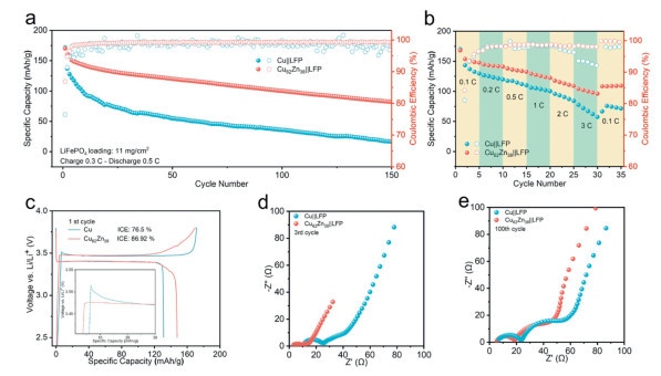
Cu-Zn solid solutions are investigated as advanced current collector materials for anode-free Li metal batteries (AFLMBs), addressing the limited lithiophilicity and slow Li+ diffusion kinetics inherent to conventional Cu foil. Benefiting from the uniform distribution of lithiophilic Zn, Cu-Zn solid solutions demonstrated enhanced lithiophilicity and accelerated Li+ diffusion, which effectively facilitated uniform and reversible lithium deposition. First-principles calculations confirmed that Cu-Zn solid solutions, particularly Cu62Zn38, exhibited stronger Li adsorption and reduced diffusion barriers compared to Cu. Unlike alloy-prone metal coatings (e.g., Cu@Zn and thermally processed Cu@Zn) that sacrifice interfacial stability for lithiophilicity, Cu-Zn solid solution maintains robust electrode-electrolyte interfaces due to its alloying inertness. Ex-situ SEM and COMSOL simulations revealed dendrite-suppressed and homogeneous Li deposition on Cu62Zn38. In anode-free full cells, Cu62Zn38 achieves a capacity retention of 55.1% after 150 cycles, far exceeding Cu foil (13.8%). This work establishes Cu-Zn solid solutions current collectors as a scalable solution for high-energy-density AFLMBs.
Rising global energy demands and environmental concerns require advanced energy storage technologies with high energy density and long cycle life [1,2]. While conventional lithium-ion batteries (LIBs) dominate commercially, they are approaching theoretical performance limits, driving the development of next-generation alternatives [3,4]. Lithium metal batteries (LMBs) represent promising candidates for the next-generation of high energy batteries due to ultrahigh theoretical specific capacity (3860 mAh/g) and low working electrochemical potential (−3.04 V) of lithium anode [5,6]. Anode-free lithium metal batteries (AFLMBs) further enhance energy density by eliminating excessive Li metal [7,8], simplifying manufacturing process while avoiding lithium anode issues. However, AFLMBs inherit intrinsic challenges of LMBs, including dendritic growth, unstable solid-electrolyte interphase (SEI), and parasitic reactions, while facing added complexity from absent lithium reservoirs [9,10]. Crucially, lacking pre-existing lithium metal induces nonuniform deposition and irreversible lithium loss, accelerating dendrite formation and capacity degradation [11].
Significant advances in electrolyte design [12–15], interface engineering [16–18], and current collector design [19–21] provide promising strategies to overcome challenges and unlock the potential of AFLMBs for next-generation energy storage applications. As we know, the current collector plays a crucial role in regulating lithium nucleation behaviors and deposition morphologies, with surface lithiophilicity and Li+ diffusion kinetics being the key factors. Conventional copper (Cu) foil has relatively low lithiophilicity, leading to inhomogeneous lithium deposition and dendrite formation [22]. Surface coating techniques (e.g., carbon, metal or metal oxide coatings) have been employed to improve interface lithiophilicity and promote uniform lithium deposition, further bringing AFLMBs closer to practical deployment [23–25].
Metals that alloy with lithium (Zn, Sn, Ag, Au, etc.) have been extensively studied as surface coatings due to their strong lithiophilicity, which could promote uniform lithium nucleation and suppresses dendrite formation [26–28]. However, the alloying process inevitably involves substantial volume expansion, leading to interface degradation and poor cycling reversibility. To mitigate these effects, recent efforts have focused on constructing intermetallic alloy coatings to buffer volume effects, but such strategies remain limited by inherent alloying-induced fluctuations, and also increase fabrication complexity and costs. Accordingly, we turned our attention to solid-solution alloy foils, which offer a promising yet unexplored approach for AFLMBs. Specifically, Cu-Zn solid-solution (brass) have emerged as a promising candidate due to the high lattice compatibility between Cu and Zn, which enables the formation of solid-solution phases with uniformly distributed Zn atoms within stable Cu lattice. These embedded Zn sites not only act as effective lithiophilic centers, but also inert to lithium alloying reaction due to the refrain of Cu matrix, ensuring both interfacial lithiophilicity and stability during cycling. Furthermore, brass foil is low-cost, scalable, and compatible with conventional foil manufacturing, making it an attractive candidate for current collector used in anode-free systems.
Herein, we systematically investigated the feasibility of employing commercial Cu-Zn solid solutions foils with varying Zn contents as current collectors for AFLMBs. Specifically, Cu-Zn solid solutions foil with Zn mass fractions of 32%, 35%, and 38% (Cu68Zn32, Cu65Zn35, and Cu62Zn38), representing typical brass compositions, were used and compared with commercial Cu foil. For the exploration of the Zn and Cu-Zn intermetallic phase coatings, Zn coatings were introduced onto Cu foil using magnetron sputtering. Further, the Cu@Zn was thermally treated at 350 ℃ to generate Cu-Zn intermetallic phases, enabling a direct comparison between solid-solution alloys and intermetallic phases. Both Cu-Zn solid solutions foils and commercial Cu foil remain inert toward lithium alloying reaction during cycling, and the Cu-Zn solid solution with the highest Zn content (Cu62Zn38) exhibits favorable lithiophilicity and Li+ diffusion kinetics, attributed to the uniform distribution of lithiophilic Zn within the Cu matrix. Although Zn and Cu-Zn intermetallic phase coatings display stronger lithiophilicity, they undergo lithiation/de-lithiation during cycling, leading to interfacial instability. This work highlights the unique advantages of Cu-Zn solid solutions, which simultaneously achieves chemical stability, lithiophilicity, and practical processability, offering a compelling alternative for current collector in AFLMBs.
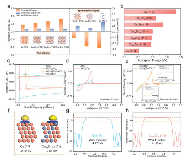
To systematically evaluate the lithiophilicity and interfacial stability of Cu and various Cu-Zn based current collectors, first-principles calculations and electrochemical analyses were performed (Fig. 1). Fig. 1a shows the calculated formation energies and corresponding volume expansion ratios between a single lithium and different substrates. Cu and Cu-Zn solid solutions all demonstrate positive formation energies and minimal volume expansion, indicating their unfavorable lithiation tendency and excellent structural stability. In contrast, Cu-Zn intermetallic phases and pure Zn show negative formation energies, indicating a strong lithiation tendency. This enhanced reactivity leads to much higher volume expansion, which induces interfacial instability and non-uniform lithium deposition.
Figure 1
Figure 1.
(a) Formation energies and volume expansion ratios of single lithium with different substrates. (b) Li adsorption energies of different substrates. (c) The enlarged images of initial discharge curves of Li||Cu, Li||Cu62Zn38, Li||Cu@Zn and Li||Cu@Zn-350 ℃ half cells. (d) Cyclic voltammetry curves of Li||Cu and Li||Cu62Zn38 half cells. (e) Cyclic voltammetry curves of Li||Cu@Zn and Li||Cu@Zn-350 ℃ half cells. (f) Differential charge density of lithium adsorbed on Cu (111) and Cu62Zn38 (111) planes and (g, h) surface work functions of Cu (111) and Cu62Zn38 (111) planes.
The lithium adsorption energies on various current collectors, a key indicator of surface lithiophilicity, are shown in Fig. 1b. Compared to Cu, Cu-Zn solid solutions exhibit enhanced lithiophilicity, which increases progressively with higher Zn content. Cu-Zn intermetallic compounds and pure Zn both exhibit enhanced lithium adsorption, with pure Zn displaying the highest lithiophilicity among all samples. These trends are consistent with electrochemical results of nucleation overpotentials (Fig. 1c and Figs. S1–S3 in Supporting information). All Cu-Zn solid solutions samples demonstrate much lower overpotentials compared to Cu, and the Cu62Zn38 with the highest Zn content exhibits the lowest nucleation overpotential, indicating its superior nucleation kinetics. In addition, the initial discharge curves of Cu-Zn solid solutions foils display no lithiation plateaus, confirming the absence of alloying reactions during cycling. In contrast, although Cu@Zn-350 ℃ and Cu@Zn electrodes exhibit stronger lithiophilicity, lithiation happens during the initial discharge process, consistent with their negative formation energies. This alloying reaction not only compromises interfacial stability but also consumes active lithium, thereby undermining the viability of anode-free configurations. Cyclic voltammetry (CV) test further validates these results (Figs. 1d and e). The peak intensities of Cu62Zn38, Cu@Zn-350 ℃, and Cu@Zn electrodes are significantly higher than those of Cu, indicating their enhanced Li+ transport kinetics. Notably, Cu and Cu62Zn38 electrodes exhibit no additional redox peaks, while Cu@Zn and Cu@Zn-350 ℃ electrodes show distinct initial reduction peaks, indicating alloying reaction happens. The half-cell cycling performances (Figs. S4–S6 in Supporting information) further corroborate these observations. As seen, Cu62Zn38 delivers the highest average Coulombic efficiencies (CE) of 98.7% and superior long-term stability. The average CE of Cu@Zn and Cu@Zn-350 ℃ is 98.39% and 98.5%, respectively, primarily due to interfacial degradation from alloying. Cu foil fails after ~250 cycles due to its poor lithiophilicity and severe dendritic growth.
To gain further insights into the superior performance of Cu-Zn solid solutions, differential charge density analysis was performed on Cu and Cu62Zn38 adsorbed with single lithium (Fig. 1f). Cu62Zn38 shows stronger charge transfer and higher electron density accumulation at the lithium adsorption site, indicating enhanced electron transportation that facilitates lithium reduction. Furthermore, surface work function calculations for the (111) plane of Cu and Cu62Zn38 (Figs. 1g and h) reveal that Cu62Zn38 has a lower work function, suggesting more efficient interfacial electron transfer.
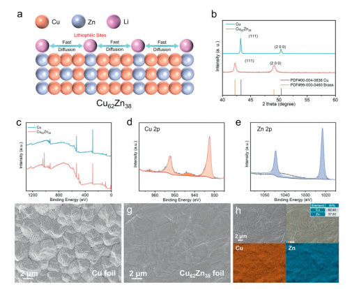
Building upon the crystal structure and surface properties discussed in Fig. 1, the phase composition and morphology of the current collectors were further analyzed (Fig. 2). The schematic diagram of the crystal structure of Cu62Zn38 is shown in Fig. 2a. The exposed Zn atoms on the surface serve as lithiophilic sites, significantly enhancing uniform lithium nucleation and promoting fast lithium diffusion, thereby enabling uniform and reversible lithium deposition. The X-ray diffraction (XRD) patterns (Fig. 2b and Fig. S7 in Supporting information) confirm the phase compositions of Cu and various Cu-Zn based current collectors. Compared to Cu, the diffraction peaks of Cu62Zn38 slightly shift to lower angles, indicating lattice expansion due to the incorporation of Zn atoms into the Cu matrix, consistent with its solid-solution structure. Cu@Zn shows diffraction peaks corresponding to Zn, confirming the successful introduction of Zn onto the Cu foil. Upon annealing at 350 ℃, diffraction peaks of Cu1Zn1 and Cu5Zn8 intermetallic phases are observed in Cu@Zn-350 ℃, suggesting that alloying reaction between Cu and Zn occurred under the heat treatment condition. Figs. 2c-e show the X-ray photoelectron spectroscopy (XPS) spectra for Cu and Cu62Zn38 foils, confirming the presence of Cu and Zn on the Cu62Zn38 foil surface. To investigate the surface morphology, scanning electron microscope (SEM) images of various current collectors are shown in Figs. 2f and g, Figs. S8 and S9 (Supporting information). Both Cu and Cu62Zn38 foils display a two-dimensional and planar morphology. Uniformly distributed Zn nanoparticles (~30 nm) are observed on the surface of Cu@Zn. Following heat treatment at 350 ℃ for 2 h, the Cu@Zn-350 ℃ sample exhibits morphological irregularities and partial aggregation, likely resulting from alloy formation processes. Fig. 2h presents the SEM-EDS mapping results of Cu62Zn38 foil, clearly demonstrating the uniform distribution of Cu and Zn elements.
Figure 2
Figure 2.
(a) Crystal structure of Cu-Zn solid solution (Cu62Zn38), highlighting its structural advantages. (b) XRD patterns of Cu and Cu62Zn38. (c) XPS survey spectra of Cu and Cu62Zn38. (d) Cu 2p spectrum of Cu62Zn38. (e) Zn 2p spectrum of Cu62Zn38. (f, g) SEM images of Cu foil and Cu62Zn38 foil and (h) corresponding EDS mapping results of Cu62Zn38 foil.
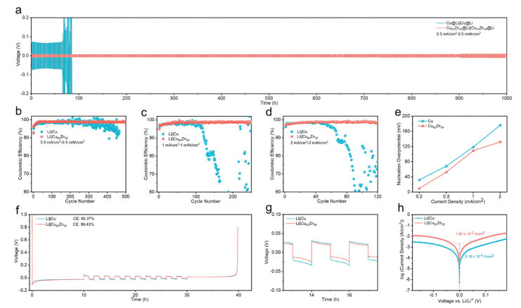
To evaluate the lithium deposition behaviors of Cu and Cu62Zn38 current collectors, symmetric cells were assembled with pre-deposited lithium (2 mAh/cm2). As shown in Fig. 3a, Cu exhibits higher polarization and significantly poorer cycling stability compared to Cu62Zn38. The Cu62Zn38 symmetric cell demonstrates lower overpotential and stable operation for over 1000 h. This superior electrochemical behavior of Cu62Zn38 was further confirmed by CV and electrochemical impedance spectroscopy (EIS) test (Figs. S10–S12 in Supporting information). As seen, Cu62Zn38 demonstrates significantly stronger oxide-redox signals and a higher exchange current density than Cu, indicating its enhanced electrochemical reactivity. EIS results also show lower impedance for Cu62Zn38, confirming its superior charge transfer capacity.
Figure 3
Figure 3.
Electrochemical performance of Cu and Cu62Zn38 in symmetric cells and half cells: (a) Cycling performances of Cu@Li||Cu@Li and Cu62Zn38@Li||Cu62Zn38@Li symmetric cells. (b–d) Coulombic efficiencies of Li||Cu and Li||Cu62Zn38 at 0.5 mA/cm2–0.5 mAh/cm2, 1 mA/cm2–1 mAh/cm2 and 2 mA/cm2–2 mAh/cm2. (e) Nucleation overpotentials of Cu and Cu62Zn38 at different current densities. (f, g) Aurbach test results of Cu and Cu62Zn38 and (h) exchange current density results of Li||Cu and Li||Cu62Zn38 half cells.
Further, Li||Cu and Li||Cu62Zn38 half-cells were assembled to evaluate the reversibility of lithium deposition. As shown in Figs. 3b-d, Cu62Zn38 demonstrates superior cycling performance and higher CE compared to Cu at various current densities of 0.5, 1, and 2 mA/cm2, respectively. The corresponding nucleation overpotential results (Fig. 3e) reveal Cu62Zn38 has lower nucleation barriers, consistent with its superior electrochemical activity and stability. To precisely assess the average CE of the current collectors, the Aurbach test was employed (Figs. 3f and g). As seen, Cu62Zn38 exhibits higher average CE and lower polarization compared to Cu, highlighting its superior electrochemical performance.
To further investigate the electrochemical reactivity and Li+ diffusion behaviors of the current collectors, CV, EIS and galvanostatic intermittent titration technique (GITT) tests were conducted. As shown in Fig. 3h, Cu62Zn38 shows much higher exchange current density (1.9 × 10⁻³ A/cm2), indicating its enhanced electrochemical activity compared to Cu (3.18 × 10⁻⁴ A/cm2). EIS measurements (Fig. S13 in Supporting information) reveal a lower charge transfer resistance for Cu62Zn38, suggesting improved ion transport and faster reaction kinetics. Moreover, the GITT results (Fig. S14 in Supporting information) indicate that Cu62Zn38 shows higher Li+ diffusion coefficient (5.624 × 10⁻¹³) than Cu (3.715 × 10⁻¹³). These findings collectively highlight the enhanced electrochemical reactivity and ion diffusion capabilities of Cu62Zn38, which facilitates more uniform Li deposition.
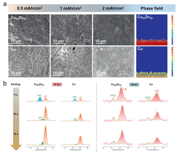
Furthermore, ex-situ SEM characterizations were conducted on current collectors after depositing different amounts of lithium (Fig. 4a). At low deposition amounts, the Cu62Zn38 foil forms smaller and denser lithium nuclei, while the Cu exhibits irregular and coarse lithium depositions. This suggests that the excellent lithiophilicity of the Cu62Zn38 surface provides more uniform and dense nucleation sites. As the deposition amount increases, lithium metal is uniformly deposited on the Cu62Zn38 foil surface with a two-dimensional pattern, whereas the depositions are uneven and aggregated on the Cu foil, confirming the superior nucleation and growth behaviors of lithium metal on the Cu62Zn38 foil. These results further support the superior Li+ diffusion capability of Cu62Zn38. DFT calculations reveal that Cu62Zn38 possesses a lower Li+ diffusion barrier than Cu, suggesting enhanced ion transport kinetics (Fig. S15 in Supporting information). Additionally, finite element simulations based on the phase-field model were performed to study the lithium deposition behaviors on different current collectors using COMSOL Multiphysics 6.2 (Fig. 4a). Cu62Zn38 enables a more homogeneous and uniform lithium deposition. In contrast, Cu exhibits highly uneven deposition and favors dendritic Li growth. These simulation results are consistent with the SEM observations, further highlighting the critical role of surface lithiophilicity and Li+ transport kinetics in dictating lithium depositing behaviors. Further, XPS depth profiling was employed to compare the SEI composition on the cycled Cu and Cu62Zn38 electrodes (Fig. 4b). The inner SEI on the Cu62Zn38 electrode is distinctly enriched in LiF (F 1s at 684.8 eV) and Li3N (N 1s at 398.3 eV) compared to that on pure Cu, which are key components to its superior mechanical and ionic transport properties, explaining the excellent interfacial stability of the Cu-Zn solid solution current collector.
Figure 4
Figure 4.
(a) SEM images of Cu and Cu62Zn38 foils with different lithium deposition amounts and phase-field simulation results of lithium deposition on Cu and Cu62Zn38. (b) XPS spectra for F 1s and N 1s of the electrode surfaces of cycled Li||Cu62Zn38 and Li||Cu batteries.
Anode-free batteries were assembled to evaluate the practical application of Cu62Zn38. As shown in Fig. 5a, Cu62Zn38 foil displays much superior cycling stability with a capacity retention of 55.1% after 150 cycles under a 0.3 C/0.5 C charge/discharge protocol, while that of Cu is only 13.8%. In addition, both Cu@Zn and Cu@Zn-350 ℃ demonstrates improved electrochemical performance than Cu, attributed to their superior lithiophilicity (Fig. S16 in Supporting information). However, their long-term cycling stability is invariably compromised. The repetitive volume changes of these coatings during lithiation/delithiation induce continuous mechanical degradation and interfacial reconstruction, leading to rapid capacity fade. In contrast, the Cu62Zn38 foil effectively avoids this issue due to its inherent structural stability. Fig. 5b also shows much better rate capability of Cu62Zn38 with a high capacity of 104.09 mAh/g even at a current density of 3 C. The initial charge-discharge curves (Fig. 5c) demonstrate an extremely weak nucleation overpotential for Cu62Zn38, confirming its excellent lithiophilicity. The higher reversibility of lithium deposition behaviors on Cu62Zn38 is also revealed by its higher initial Coulombic efficiency (86.92%) than Cu (76.5%). Furthermore, comparative charge-discharge curves of Cu and Cu62Zn38 reveals superior stability in the Cu-Zn solid solution, evidenced by well-maintained voltage profiles across cycles (Fig. S17 in Supporting information). This enhanced cycling performance arises from Cu62Zn38’s improved lithiophilicity and robust interfacial stability. Supporting evidence from EIS measurements (Figs. 5d and e) demonstrates consistently lower SEI and charge transfer resistances than Cu, confirming stable interface formation and sustainable long-term cycling capability.
Figure 5
Figure 5.
(a) Cycling performance of Cu||LFP and Cu62Zn38||LFP anode-free batteries at 0.3 C charge and 0.5 C discharge rates with LiFePO4 mass loading of 11 mg/cm2, the batteries were first cycled for three cycles at 0.1 C. (b) Rate performance of Cu||LFP and Cu62Zn38||LFP anode-free batteries at increasing rates from 0.1 C to 3 C. (c) The charge-discharge curves of the first cycle of Cu||LFP and Cu62Zn38||LFP anode-free batteries and (d, e) EIS results of Cu||LFP and Cu62Zn38||LFP anode-free batteries after 3 cycles and 100 cycles, respectively.
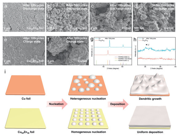
To further investigate the lithium deposition behaviors and structural stability of different current collectors during cycling, SEM images of the current collector surfaces at fully charged and discharged states after 100 cycles are shown in Figs. 6a-f. In the fully discharged state, both Cu and Cu62Zn38 exhibit noticeable particle residues, indicating the continuous accumulation of dead lithium during cycling. Upon further examination, the particles on the Cu62Zn38 surface are more uniformly distributed and smaller in size, whereas those on Cu are larger and dendritic morphologies form. Results above suggest that the Cu62Zn38 current collector maintains a more stable interface and effectively suppresses dendrite growth during cycling. In the fully charged state, Cu62Zn38 current collector displays uniform two-dimensional depositing pattern, while Cu exhibits significant localized lithium aggregation. Furthermore, XRD analysis of Cu and Cu62Zn38 current collectors after 100 cycles (Figs. 6g and h) reveals distinct dead lithium signals in Cu, which are absent in Cu62Zn38. Based on the above discussions, a schematic diagram is presented in Fig. 6i to intuitively compare the distinct lithium nucleation and deposition behaviors on Cu and Cu62Zn38 current collectors. For conventional Cu foil, its intrinsically low lithiophilicity results in heterogeneous nucleation sites, which promotes the uncontrollable dendritic morphology form and leads to interfacial degradation during cycling. In contrast, Cu62Zn38 with a homogeneous distribution of lithiophilic Zn atoms provides energetically favorable sites for Li+ adsorption and nucleation, enabling highly uniform lithium plating and maintaining a robust and stable interface throughout extended cycling. The combined structural integrity and superior lithiophilicity of Cu62Zn38 enable enhanced cycling performance, demonstrating its significant potential as a high-performance current collector for AFLMBs.
Figure 6
Figure 6.
SEM images of the current collector surfaces after 100 cycles: (a, b) Cu62Zn38 at fully discharged state, (c, d) Cu at fully discharged state, (e) Cu62Zn38 at fully charged state, and (f) Cu at fully charged state. (g, h) XRD patterns of Cu and Cu62Zn38 current collectors after 100 cycles and corresponding enlarged patterns and (i) the schematic illustration of lithium nucleation and deposition processes on different current collectors.
In summary, the Cu-Zn solid solution (Cu62Zn38) foil with superior lithiophilicity and fast Li+ diffusion rate demonstrated significant potential for use in AFLMBs. The homogeneous Zn distribution within the solid solution significantly enhanced nucleation thermodynamics and stabilized growth dynamics. In contrast, although intermetallic coatings (Cu@Zn and Cu@Zn-350 ℃) exhibited improved lithiophilicity, they experienced alloying reaction during cycling, leading to unstable interfaces and fast capacity degradation. Combined evidence from ex-situ SEM characterizations, COMSOL simulations and DFT calculations confirmed that Cu62Zn38 effectively suppressed dendrite growth and maintained electrochemical interface integrity through intrinsic alloying inertness. In anode-free batteries, the Cu62Zn38 foil demonstrated much superior cycling stability with a capacity retention of 55.1% after 150 cycles, a fourfold improvement over conventional Cu foil (13.8%). This work establishes Cu-Zn solid solution foil as an industrially scalable solution that extends AFLMB lifetime and efficiency via optimized Li+ transport and interfacial control. Future integration of modified Cu-Zn solid solution current collectors with high-capacity cathodes (e.g., Li-rich cathode) may unlock >400 Wh/kg AFLMBs, positioning them as a viable platform for next-generation high-energy batteries.
CRediT authorship contribution statement
Fan Zhang: Writing – original draft, Software, Formal analysis, Data curation. Zizhu Guo: Writing – original draft, Formal analysis, Data curation. Jin Wang: Software, Investigation, Data curation. Dan Sun: Supervision, Investigation, Formal analysis. Xiaobing Huang: Supervision, Resources, Project administration, Investigation. Qi Zhang: Supervision, Investigation, Formal analysis. Yougen Tang: Supervision, Project administration, Investigation. Yusi Yang: Supervision, Software, Resources, Formal analysis. Haiyan Wang: Writing – review & editing, Supervision, Project administration, Investigation, Funding acquisition.
Declaration of competing interest
The authors declare that they have no known competing financial interests or personal relationships that could have appeared to influence the work reported in this paper.
Acknowledgments
This research was financially supported by the National Natural Science Foundation of China (No. 22279164), the Hunan Provincial Science and Technology Plan Projects of China (No. 2017TP1001) and the Natural Science Foundation of Hunan Province (No. 2025JJ70677).
Supplementary materials
Supplementary material associated with this article can be found, in the online version, at doi:10.1016/j.cclet.2025.112057.
Figure 1
(a) Formation energies and volume expansion ratios of single lithium with different substrates. (b) Li adsorption energies of different substrates. (c) The enlarged images of initial discharge curves of Li||Cu, Li||Cu62Zn38, Li||Cu@Zn and Li||Cu@Zn-350 ℃ half cells. (d) Cyclic voltammetry curves of Li||Cu and Li||Cu62Zn38 half cells. (e) Cyclic voltammetry curves of Li||Cu@Zn and Li||Cu@Zn-350 ℃ half cells. (f) Differential charge density of lithium adsorbed on Cu (111) and Cu62Zn38 (111) planes and (g, h) surface work functions of Cu (111) and Cu62Zn38 (111) planes.
Figure 2
(a) Crystal structure of Cu-Zn solid solution (Cu62Zn38), highlighting its structural advantages. (b) XRD patterns of Cu and Cu62Zn38. (c) XPS survey spectra of Cu and Cu62Zn38. (d) Cu 2p spectrum of Cu62Zn38. (e) Zn 2p spectrum of Cu62Zn38. (f, g) SEM images of Cu foil and Cu62Zn38 foil and (h) corresponding EDS mapping results of Cu62Zn38 foil.
Figure 3
Electrochemical performance of Cu and Cu62Zn38 in symmetric cells and half cells: (a) Cycling performances of Cu@Li||Cu@Li and Cu62Zn38@Li||Cu62Zn38@Li symmetric cells. (b–d) Coulombic efficiencies of Li||Cu and Li||Cu62Zn38 at 0.5 mA/cm2–0.5 mAh/cm2, 1 mA/cm2–1 mAh/cm2 and 2 mA/cm2–2 mAh/cm2. (e) Nucleation overpotentials of Cu and Cu62Zn38 at different current densities. (f, g) Aurbach test results of Cu and Cu62Zn38 and (h) exchange current density results of Li||Cu and Li||Cu62Zn38 half cells.
Figure 4
(a) SEM images of Cu and Cu62Zn38 foils with different lithium deposition amounts and phase-field simulation results of lithium deposition on Cu and Cu62Zn38. (b) XPS spectra for F 1s and N 1s of the electrode surfaces of cycled Li||Cu62Zn38 and Li||Cu batteries.
Figure 5
(a) Cycling performance of Cu||LFP and Cu62Zn38||LFP anode-free batteries at 0.3 C charge and 0.5 C discharge rates with LiFePO4 mass loading of 11 mg/cm2, the batteries were first cycled for three cycles at 0.1 C. (b) Rate performance of Cu||LFP and Cu62Zn38||LFP anode-free batteries at increasing rates from 0.1 C to 3 C. (c) The charge-discharge curves of the first cycle of Cu||LFP and Cu62Zn38||LFP anode-free batteries and (d, e) EIS results of Cu||LFP and Cu62Zn38||LFP anode-free batteries after 3 cycles and 100 cycles, respectively.
Figure 6
SEM images of the current collector surfaces after 100 cycles: (a, b) Cu62Zn38 at fully discharged state, (c, d) Cu at fully discharged state, (e) Cu62Zn38 at fully charged state, and (f) Cu at fully charged state. (g, h) XRD patterns of Cu and Cu62Zn38 current collectors after 100 cycles and corresponding enlarged patterns and (i) the schematic illustration of lithium nucleation and deposition processes on different current collectors.


 DownLoad:

 下载:
下载:


 下载:
下载:

