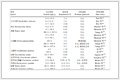
Table 1.
Comparison of different surface coating methods in terms of their advantages, disadvantages, and suitable anode types.

Recent advances in interfacial engineering of lithium battery anodes by atomic layer deposition technology
Bin Wang , Zichuan Cheng , Fengshuo Xi , Shaoyuan Li , Jijun Lu , Xiuhua Chen , Wenhui Ma


Lithium batteries are an important energy storage solution used in information systems, electric vehicles (EVs), and grid-scale energy storage due to their superior energy density and long cycle lives [1-3]. As a critical component of lithium batteries, the anode material determines the battery's energy efficiency, cycling stability, and safety [4]. Its structural and electrochemical properties determine the reliability of redox reactions and performance under extreme operating conditions. Consequently, research has focused on the design and optimization of anode materials to simultaneously achieve high energy density and enhanced safety [5-7].
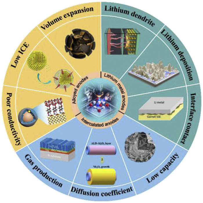
Lithium-ion battery anodes dominate the energy storage market due to their more mature technology route, cost advantages, and longer cycle lives [8,9]. Depending on the type of anode, lithium-ion batteries can be classified into either intercalation‐type anodes or alloy‐type anodes. Intercalation‐type anodes (e.g., graphite, 372 mAh/g) deliver excellent cycling stability, yet suffer from a low theoretical capacity [10-12]. Alloy‐type anodes have a high capacity (e.g., silicon, 4200 mAh/g) but undergo critical volume expansion and form unstable solid-electrolyte interphase (SEI) layers [13,14]. Meanwhile, lithium metal anodes are ideal candidates for next-generation anode materials due to their high theoretical specific capacity (3860 mAh/g) and low electrochemical potential (−3.04 V vs. standard hydrogen electrode, SHE) [15-17]. However, they experience lithium dendrite growth and unstable solid-electrolyte interphase (SEI) layer formation, which severely reduce their cycling longevity and safety [18-20]. Addressing these limitations via interfacial engineering, structural design, and electrolyte optimization has become the central focus of lithium battery anode research. There are currently three main modification strategies: (1) Structural design to mitigate volume effects using porous frameworks [21]; (2) electrolyte optimization to tailor the interfacial chemistry using functional additives [22]; and (3) interfacial engineering to enable site-specific modification with high efficiency and broad applicability [23]. Among these, interfacial engineering is the most common approach for high-energy-density systems because it suppresses parasitic reactions and dendrite formation and also enhances interfacial ion-transport kinetics and electrode structural stability.
In contemporary interface engineering, building polymer-based or inorganic artificial SEI layers is the favored strategy for establishing barriers between anode materials and electrolytes to diminish interfacial impedance and increase ionic conductivity. Methods of interfacial engineering on electrode material surfaces have included spin coating, evaporation, physical vapor deposition (PVD), chemical vapor deposition (CVD), atomic layer deposition (ALD), and sol-gel approaches. Table 1 [24-31] compares the different interfacial engineering methods with respect to their advantages and disadvantages. However, preparation techniques such as solution coating and in-situ polymerization frequently encounter challenges in forming uniform and pinhole-free coatings on geometrically complex and irregular substrate topographies. Consequently, advanced interfacial engineering techniques characterized by surface self-limiting reactions and superior conformality are important for constructing high-performance anode-electrolyte interfaces.
 DownLoad:
CSV
DownLoad:
CSV
| Method | Spin coating | Evaporation | Sol–gel | Physical vapor deposition (PVD) | Chemical vapor deposition (CVD) | Atomic layer deposition (ALD) |
| Advantages | Simple operation, low cost, suitable for rapid preparation of flat films | High deposition rate, high film purity, simple process | High adhesive strength, low cost, simple to perform | Relatively fast process, low temperature, low cost | High growth rate, simple, various precursor availability | Superior conformality and uniformity, atomic-level thickness control, excellent stability, low-temperature process, diverse chemistry |
| Challenges | Poor conformality, high material waste, empirical thickness control | Difficult composition control, poor adhesion | Nonuniform deposition, certain crystal phases require, high-temperature annealing | Slow deposition rate, impurities, small area deposition | High temperature, limited film types | Slow deposition rate, complex equipment, high cost for mass production |
| Suitable anode types | Only suitable for model studies | Primarily used for metal anodes | Most anodes | Electrodes with flat surfaces | Most anodes | All high-performance and nanostructured anodes |
Among the above interface engineering techniques, atomic layer deposition (ALD) is a highly controllable vapor-phase deposition process that enables the conformal coating of dense, uniform, and thickness-tunable passivation layers on anode surfaces [32-34]. This allows the precise regulation of interfacial reactions between electrodes and electrolytes [35]. Research has demonstrated that ALD-derived passivation layers deliver multiple benefits in terms of anode interface engineering. They act as physical barriers that isolate reactive lithium metal or other anode materials from electrolyte components, thereby suppressing parasitic reactions and mitigating dendrite growth to enhance safety. Their high mechanical strength accommodates cyclic volume fluctuations, stabilizes electrodes, and ensures solid-electrolyte interphase (SEI) continuity to minimize active lithium loss. Conductive or ion-conductive passivation layers optimize charge-transfer kinetics across electrode/electrolyte interfaces, which reduces interfacial resistance while improving the rate capability and charge-discharge efficiency. These layers can also function as rapid Li+ diffusion channels that accelerate ion transport and boost the Coulombic efficiency and cycling stability. As shown in Fig. 1, this review focuses on recent advances in the use of ALD for interfacial modification of lithium battery anodes. The review evaluates its efficacy for enhancing the cycling performance, rate capability, and capacity retention. ALD's emerging applications and development prospects for next-generation energy storage systems are explored to provide a theoretical foundation and technical guidelines for designing high-performance LIB anode materials.
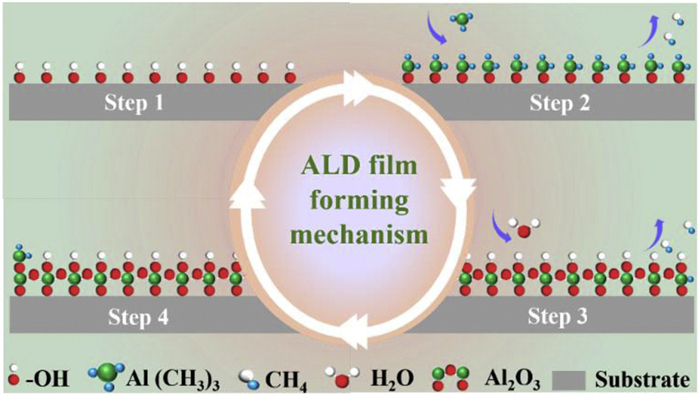
ALD is a thin-film growth technique based on self-limiting surface reactions, and it enables the layer-by-layer deposition of films with atomic-scale precision by alternating exposure to different precursors [36-38]. A typical ALD cycle consists of four distinct steps: (1) First precursor exposure, in which the first precursor is pulsed onto a substrate surface, where it undergoes chemisorption or reacts with surface active groups; (2) A purge step, during which an inert carrier gas purges unreacted precursor and byproducts; (3) Second precursor exposure, during which the second precursor is introduced to react with the adsorbed specie and form the desired thin film; (4) Final purge, during which residual precursors and reaction byproducts are removed by another purge cycle.
To illustrate this chemical process, we use the ALD of aluminum oxide (Al2O3) using trimethylaluminium [Al(CH3)3] and water (H2O) as precursors as an example:
(A) Surface hydroxyl groups react with the metal precursor:
|
|
(B) Subsequent water exposure completes the reaction:
|
|
where "├" represents the substrate surface and "(g)" denotes gas-phase species. As shown in Fig. 2, a typical ALD cycle consists of four distinct steps. This completes one full ALD cycle and results in the growth of one (sub) atomic layer of Al2O3 [39,40].
These critical factors can be categorized into four main aspects: (1) Precursor characteristics: The chemical reactivity, volatility, and adsorption of precursors directly affect the efficiency of surface reactions. Although highly reactive precursors can enhance the growth rate per cycle (GPC), careful selection is required to avoid unwanted gas-phase reactions that undermine ALD's self-limiting mechanism. (2) Temperature window: The process temperature must be carefully optimized within a defined range. If the temperature is too low, precursor adsorption will be incomplete. Conversely, excessively high temperatures may cause thermal decomposition or shift the mechanism toward CVD, thus disrupting ALD's self-limiting nature. (3) Pulse and purge durations: Precursor pulse durations must allow for complete surface saturation, while purge durations should be long enough to remove residual reactants and prevent cross-contamination between successive precursors. (4) Surface chemistry: The density and distribution of reactive surface groups (e.g., -OH) significantly affect precursor adsorption kinetics and the initial film quality. Substrates lacking sufficient active sites may exhibit delayed nucleation or non-uniform film growth [41,42].
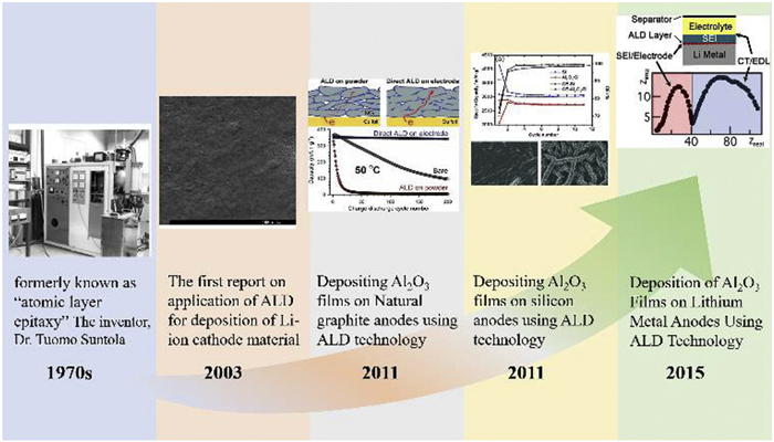
The interfacial stability of anode structures during charge-discharge cycles is one of the most critical factors governing lithium battery performance [43]. An ideal anode must exhibit a high specific capacity [44,45], low operating potential [46,47], exceptional cycling stability [48,49], high ion/electron conductivity [50-52], interfacial compatibility [53,54], minimal volume change [55], thermal stability, and chemical inertness [56,57]. However, fabricating anode materials that satisfy all these criteria is complex and challenging. Here, we categorize lithium batteries into three types based on their main advantages: Intercalation‐type anodes that are used in lithium-ion batteries requiring stability, long cycle lives, and low costs; Alloy‐type anodes preferred for high-energy-density LIBs; Lithium-metal anodes with ultralow potentials primarily deployed in lithium-metal batteries. Next, we will trace the key developments in lithium battery anode research and introduce the application of atomic layer deposition (ALD) in this field in chronological order. As illustrated in Fig. 3, representative milestones span from the invention of ALD to its early applications for anode materials, including classic studies such as Al2O3 coatings on various anodes [58-62]. The following sections describe how ALD has addressed the limitations of each anode type and future prospects of ALD for advanced energy storage devices. Table 2 summarizes recent ALD approaches for coating various anode materials, as well as the optimized electrochemical performance of the anode materials. Performance is evaluated in terms of cycling performance, initial Coulombic efficiency, and rate performance.
 DownLoad:
CSV
DownLoad:
CSV
| Material | ALD strategy | Optimum thickness | ICE (%) | Capacity retention rate | Ref. |
| MGP@TiO2 | A-TiO2 | 11 nm | 92.1 | 230 cycles at 0.1 C maintain 334.3 mAh/g | [70] |
| 2Zn-Graphite | ZnO | 2 cycles | > 92 | 500 cycles at 0.2 C maintain ~420 mAh/g | [71] |
| GAZ100 | ZnO | ~5 nm | —— | 1000 cycles at 1A/g maintain ~1000 mAh/g | [72] |
| NG-V | V2O5 | 5 nm | ~69 | 500 cycles at 1A/g maintain 365 mAh/g | [73] |
| Mn3O4@CNT/TiO2 | TiO2 | ~3 nm | ~90 | 200 cycles at 0.2 A/g maintain 740.7 mAh/g | [74] |
| Si-Gr | ZnO | 3.4nm | 65.7 | 140 cycles at 1 C maintain 285 mAh/g | [75] |
| 250–10AZO | Al-doped ZnO (AZO) | ~2.5 nm | —— | 100 cycles at 5 C maintain ~159 mAh/g | [77] |
| LTO | Al2O3 | ~2 nm | > 90 | Outstanding 98% capacity retention after 500 cycles | [79] |
| ALD Li4Ti5O12 | LTO | ~30 nm | > 95 | Outstanding 97.9% capacity retention after 1000 cycles | [80] |
| ALD Li4Ti5O12 | LTO | 50 nm | 99.9975 | Outstanding 97.5% capacity retention after 1000 cycles | [81] |
| TiN@N-LTO | LTO | — | > 90 | Capacity retention of 99.6% after 5000 cycles at 10 C | [82] |
| Si-AlOxNy-30 | AlOxNy | 30 cycles | 67 | 140 cycles at 0.1 C maintain 1297 mAh/g | [93] |
| Al2O3–2 | Al2O3 | ~30 nm | 92.5% | 300 cycles at 0.1 C maintain 1013 mAh/g | [95] |
| Si + 20 nm AlF3 | AlF3 | 5 nm, 20 nm | 70.6 | 100 cycles at 0.5 C maintain ~3157 mAh/g | [100] |
| Si@Li2O-lithicone | Li2O-lithicone | ~5 nm | 91.2 | 850 cycles at 2 A/g maintain 646 mAh/g | [101] |
| Si@zincone/TiO2 | zincone/ TiO2 | ~5 nm | 81.9 | 1000 cycles at 2 A/g maintain 753 mAh/g | [102] |
| Si@Li2O@TiO2 | Li2O@TiO2 | Li2O (~1 nm), TiO2 (~4 nm) | 90.9 | 1150 cycles at 2 A/g maintain 1300 mAh/g | [103] |
| SnO2@TiO2 | TiO2 | ~3 nm | ~65 | 100 cycles at 0.08A/g maintain 1259 mAh/g | [107] |
| SnO2/NC@TiO2 | TiO2 | 10nm | 72.3 | 200 cycles at 1 A/g maintain ~869 mAh/g | [110] |
| CoSn2 and Ni3Sn4 | Al2O3 | 10 cycles | ~99 and ~100 | 100 cycles at 1 A/g maintain ~400 and ~300 mAh/g | [113] |
| Li/C-ALD | ZnO | 50 nm | —— | Ultra-long lifespan of 400 cycles at 3.0 mA/cm2 | [126] |
| LiZn/Li2O | ZnO | —— | —— | Cycle life exceeding 3000 h at 3 mA/cm2 | [127] |
| Li/50TiO2 | TiO2 | 50 nm | —— | Stable cycling for over 500 h at 10 mA/cm2 | [128] |
| Titania (5 nm) cell | TiO2 | 5 nm | —— | Stable cycling for over 150 cycles at 1 mA/cm2 | [129] |
In lithium-ion batteries, intercalation-type anodes store lithium through electrochemical reactions that involve the insertion of lithium ions into the interlayers of a layered anode [63-65]. Graphite anodes are the dominant commercial option due to their high reversibility, low cost, long cycle life, and minimal volume expansion during lithiation [66,67]. However, intercalation-type anodes still face challenges regarding achieving a higher capacity, ultrafast charging, and improved low-temperature performance. These properties are critical for emerging applications such as solid-state batteries and electric aviation. Addressing these limitations requires advancements in material design and engineering to meet the stringent demands of next-generation energy storage technologies.
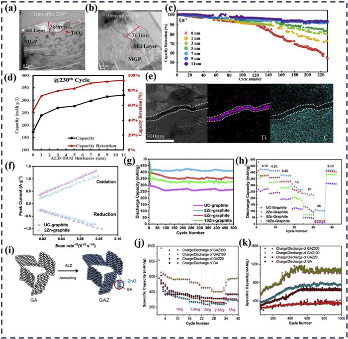
Graphite anodes have a low lithium intercalation potential (0.1 V vs. Li/Li+), but they are prone to the formation of an SEI [55]. Uniform passivation layers (e.g., TiO2, SnO2, ZnO, Al2O3) via ALD are physical barriers that suppress interfacial side reactions and mitigate repeated SEI growth [68,69]. Previous studies have demonstrated that the thickness of the passivation layer significantly influences the rate capability and capacity retention. Wu et al. investigated the impact of amorphous titanium dioxide (A-TiO2) nanocoating thickness (1–11 nm) on graphite anodes [70]. The coatings were deposited via ALD, and their structural characteristics are illustrated in Figs. 4a and b. The A-TiO2 layer isolated ion diffusion from electrolyte degradation products, preventing further reactions between graphite and the electrolyte. Via this protective mechanism, an 11 nm A-TiO2 coating achieved a capacity retention of 93.6% after 230 cycles, compared with 52.2% for uncoated graphite (Fig. 4c). The correlation between coating thickness and cycling performance, along with a cross-sectional view of the 11 nm A-TiO2-coated graphite anode, is shown in Figs. 4d and e. Different metal passivation layers exhibited distinct effects. For example, oxygen vacancies or Zn2+ defects in ZnO can act as rapid Li+ migration channels that reduce the interfacial diffusion resistance. ZnO preferentially forms a dense passivation layer with the electrolyte, which helps minimize side reactions on the graphite surface. Helaley et al. demonstrated that an ultrathin ZnO interlayer significantly improved the rate capability and cycling stability of graphite anodes [71], and the Li+ diffusion coefficient of the 2Zn-graphite composite electrode surpassed that of pristine graphite (Fig. 4f). Enhanced ion transport resulted in superior cycling capacity and rate performance, as shown in Figs. 4g and h. However, using an excessive ZnO thickness may adversely affect the resulting performance. As shown in Fig. 4i, Wang et al. deposited ZnO layers over 100, 200, and 300 cycles and revealed significant performance variations between the resulting electrodes [72]. The GAZ100 electrode (graphene aerogel/ZnO nanofilm) delivered a reversible capacity of 400 mAh/g at 2500 mA/g, while GAZ300 achieved only ~200 mAh/g (Fig. 4j). The flexible graphene aerogel (GA) could accommodate volume changes in ZnO during cycling, which enabled the GAZ composite to maintain a specific capacity of 1200 mAh/g (Fig. 4k).
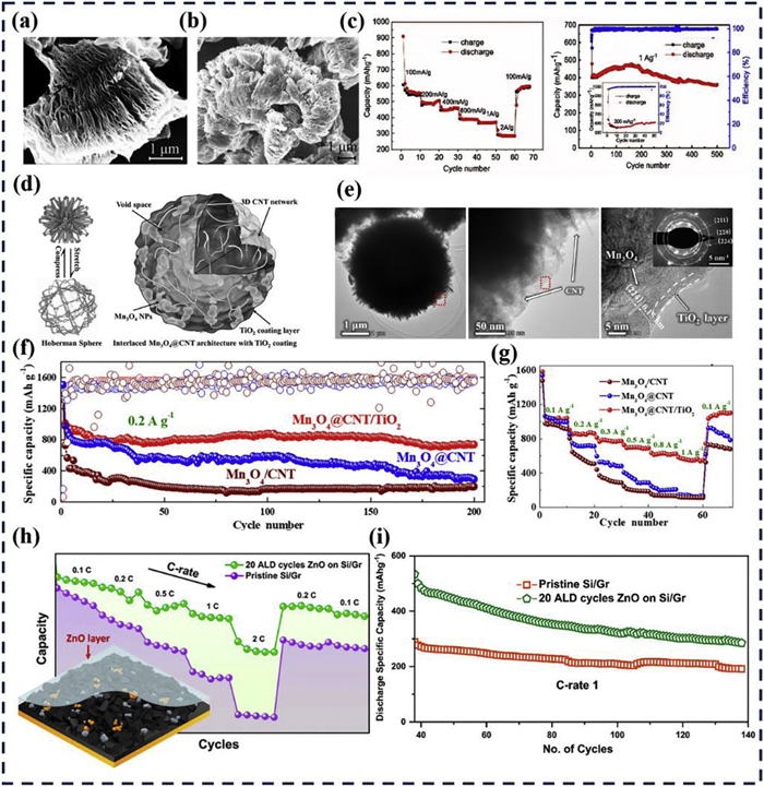
Although graphite anodes show longer cycling capabilities, they still show limited capacities (372 mAh/g) [63]. Metal oxides possess inherent cycling capacities, allowing them to serve dual functions as both passivation layers and active anode materials. Zhao et al. used ALD to incorporate V2O5, which remarkably improved the material's cycling stability [73]. The three-dimensional structure formed by V2O5 grown on graphite provided efficient pathways for Li+ and electron transport while mitigating volume expansion induced by electrochemical reactions (Figs. 5a and b). The NG-V electrode demonstrated excellent capacity retention at a current density of 1000 mA/g, delivering 365 mAh/g after 500 cycles and a superior rate capability (Fig. 5c). Despite its considerable theoretical capacity (936 mAh/g), Mn3O4 still faces kinetic limitations and structural stability issues. Mao et al. used carbon nanotubes (CNTs) to construct an interwoven composite with Mn3O4 nanoparticles that exploited the CNTs' ion transport and mechanical stability [74]. The composite was further enhanced by using ALD to grow an ultrathin TiO2 coating, and the resulting hierarchical architecture is shown in Fig. 5d. High-resolution transmission electron microscopy (HRTEM) images (Fig. 5e) revealed the structural characteristics of the Mn3O4@CNT/TiO2 composite, including its three-dimensional interconnected CNT network and TiO2 layer. The ALD-deposited TiO2 layer helped stabilize the SEI, which gave the Mn3O4@CNT/TiO2 composite exceptional cycling stability over 200 cycles at 0.2 A/g (Figs. 5f and g). The high capacity was attributed to the effects of Mn3O4 (936 mAh/g) and TiO2 (~168 mAh/g). Silicon has a high theoretical capacity, making it a promising anode material when combined with carbonaceous materials. Sahoo et al. enhanced both the capacity and rate performance of silicon-graphite (Si-Gr) anodes by incorporating a metal oxide layer grown via ALD [75]. A schematic diagram of modified Si-Gr is shown in Fig. 5h. The ZnO-modified Si-Gr anode demonstrated better capacity retention (89.2%) than the unmodified electrode (62.5%) (Fig. 5i). They showed the dual role of the ZnO layer, which suppressed electrolyte decomposition, thereby stabilizing the SEI, and also alleviated the volume expansion of silicon. The passivating effect of ALD-ZnO reduced active lithium loss, thereby improving the energy density and cycling stability of the battery.
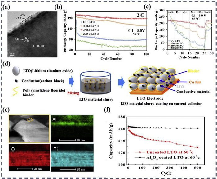
Lithium titanate (LTO) anodes exhibit an insertion/extraction voltage of approximately 1.55 V, which prevents the reduction of organic electrolytes and the formation of an SEI. However, its practical applications in next-generation LIBs are constrained by several inherent limitations, including low specific capacity, limited lithium-ion diffusion coefficients (~10–9–10–13 cm2/s), poor rate capability, interfacial side reactions that lead to gas evolution, and sensitivity to certain electrolytes [76]. To mitigate the continuous electrolyte consumption and preserve the capacity of LTO, Jin et al. used ALD to coat the surface of LTO with an ultrathin aluminum-doped zinc oxide (AZO) film [77]. The TEM image of the AZO layer exhibited a uniform distribution of AZO on the LTO particles (Fig. 6a). Cycling tests and rate performance analyses (Figs. 6b and c) demonstrated that the AZO coating suppressed electrolyte decomposition, thereby protecting the underlying LTO and helping it maintain its capacity. The 250–10AZO sample deposited at 250 ℃ retained approximately 96% of its initial capacity, decreasing from 224 mAh/g to 216 mAh/g, even at 55 ℃. The schematic representation in Fig. 6d shows the mechanism by which the AZO film protected against electrolyte-induced degradation of LTO. The ALD-modified interfacial passivation layer suppressed electrolyte decomposition reactions at the electrode surface while simultaneously inhibiting undesirable gas evolution, thereby enhancing both battery safety and the specific capacity of LTO [78]. Yoon et al. employed ALD to fabricate an ultrathin Al2O3 protective coating on LTO electrodes [79]. HRTEM images were combined with energy-dispersive X-ray spectroscopy (EDS) elemental mapping to confirm the homogeneous formation of the Al2O3 layer over the LTO surface (Fig. 6e). Electrochemical evaluation at 60 ℃ demonstrated that the Al2O3-coated LTO electrode retained approximately 98% of its capacity after 500 cycles, which was superior to the unmodified LTO electrodes. Fig. 6f presents comparative voltage profiles and cycling stability data, which reveal that the enhanced high-temperature electrochemical performance originated from the passivation layer's ability to mitigate excessive gas-generating reactions between the electrolyte and LTO. This study confirms the efficacy of ALD at improving the thermal stability and cycling performance of LTO anodes and highlights the potential application of Al2O3, TiO2, and AZO-coated LTO as an advanced anode electrode for LIBs.
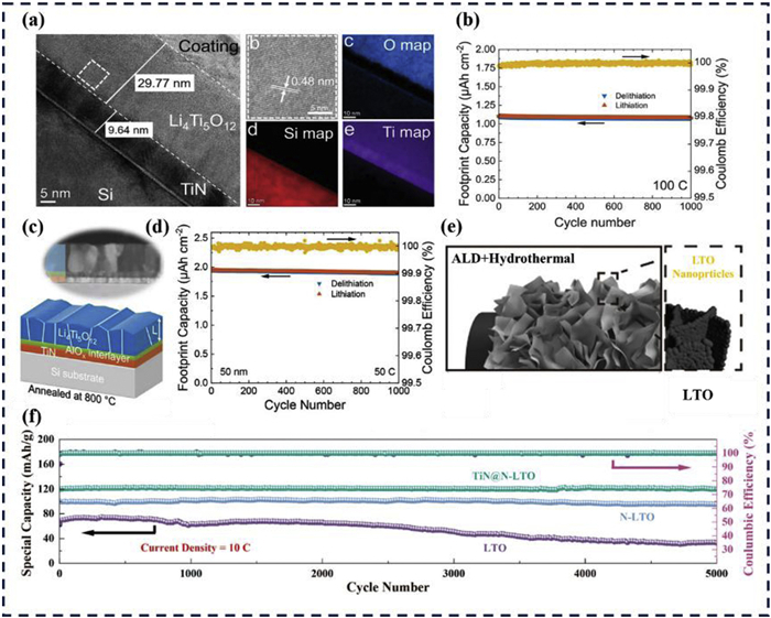
Similarly, Atomic layer deposition (ALD) enables the direct fabrication of LTO thin-film anodes using of deposition and post-annealing crystallization. Unlike conventional approaches that use LTO as a substrate for modification, this method produces dense, well-adhered spinel LTO films with optimized ion and electron transport pathways. The resulting thin-film electrodes exhibited significantly enhanced rate capabilities, making ALD-synthesized LTO a promising strategy for developing high-power lithium titanate batteries and high-rate anode materials. Speulmanns et al. successfully developed a three-step ALD process using lithium hexamethyldisilazide (LiHMDS) as a precursor, which resulted in high-quality spinel ALD Li4Ti5O12 films [80]. ALD enabled the preparation of 29.77 nm-thick LTO, as verified from SEM-EDS results (Fig. 7a). The dense spinel films produced by ALD possessed short Li+ diffusion pathways, giving them exceptional electrochemical performance, including ultra-long cycling stability (97.9% capacity retention after 1000 cycles) even at a current density of 100 C (Fig. 7b). The influence of the substrate on the crystallization behavior and film texture was also investigated in this study. Speulmanns et al. also reported that adding an AlOx layer to the TiN coating resulted in superior electrochemical performance [81]. As shown in the structural diagram in Fig. 7c, this material (ALD LTO) achieved a combination of a high areal capacity and power capability while maintaining outstanding cycling performance (Fig. 7d). The influence of TiN and TiN/AlOx interlayers on the film crystallization are also discussed. Tang et al. proposed a strategy involving the modification of vertical graphene (VG) with a TiN interlayer, followed by the ALD of nitrogen-doped lithium titanate (N-LTO) as an anode for LIBs [82]. Fig. 7e shows a schematic diagram of the ALD process, wherein the introduced TiN acted as a conductive bridge that homogenized the charge distribution and accelerated the Li+ transport kinetics. Fig. 7f shows that the TiN@N-LTO electrode demonstrated remarkable cycling stability, with 99.6% capacity retention after 5000 cycles at 10 C. These studies highlight the significant potential of ALD for fabricating highly stable LTO-coated electrodes for advanced energy storage systems.
The aforementioned studies primarily focused on how ALD could be used to modify anode materials such as graphite, Li4Ti5O12 (LTO), and graphene. ALD coatings mitigate interfacial side reactions, suppress the unstable growth of the SEI layer, and enhance the cycling stability. ALD is also employed in composite structural designs to improve electrical conductivity and achieve a high-capacity output. Extensive studies have demonstrated that ALD exhibits significant potential for enhancing the stability of intercalation-type anode electrodes, optimizing interfacial architectures, and improving overall electrochemical performance.
Alloy-type anodes (e.g., Si and Sn alloys) in lithium-ion batteries show an exceptional specific capacity, high energy density, and enhanced safety profiles [83,84]. Unlike intercalation materials, alloy-type anodes exhibit minimal atomic framework constraints, enabling them to accommodate more lithium, thus giving them superior theoretical capacities and energy/power densities. However, their practical applications are limited by severe structural degradation during lithiation/delithiation that manifests as particle pulverization. This exacerbates interfacial instability by inducing repetitive fracture and reformation of the SEI layer. Consequently, parasitic reactions between the electrode and electrolyte persist and accelerate capacity fading and compromise the cycling stability.
Silicon anodes possess a lithiation voltage plateau of approximately 0.2–0.3 V, which helps avoid the formation of lithium dendrites. However, the severe volume expansion during lithiation, accompanied by continuous reactions between the electrolyte and electrode, ruptures or reconstructs the SEI [85]. Mitigation strategies include surface modification [86], structural engineering [87], and composite formation with carbon materials [88,89]. ALD-based interfacial engineering plays an important role in alleviating volume expansion and SEI reconstruction of silicon anodes, thereby reducing capacity loss and improving the cycling stability and initial Coulombic efficiency [90]. Significant progress has been made in addressing the structural stability of silicon-based materials via ALD [91,92]. This is due to the ability of mechanically robust coatings to buffer internal volume expansion. Zhu et al. applied plasma-enhanced atomic layer deposition (PEALD) to deposit AlOxNy coatings on silicon anodes. The uniform Al/Si distribution and 1297 mAh/g capacity retention after 140 cycles (versus bare Si) demonstrated suppressed volume expansion and mitigated interfacial side reactions (Figs. 8a-d) [93]. Al2O3 is used as a passivation layer and has also been applied to silicon anodes. However, due to its electrochemical inertness, excessively thick Al2O3 layers can hinder ion diffusion and impair electrochemical kinetics [94]. Lee et al. investigated how Al2O3 layers with different thicknesses confined volume expansion [95]. Although the Al2O3 coating did not significantly improve the initial Coulombic efficiency, it did prevent direct contact between the active powder and electrolyte (Fig. 8e). Al2O3–2 showed the best structural stability during long-term cycling (Fig. 8f). A uniform and intact Al2O3 layer inhibited continuous electrolyte decomposition and delamination of the electrode from the current collector (Fig. 8g).
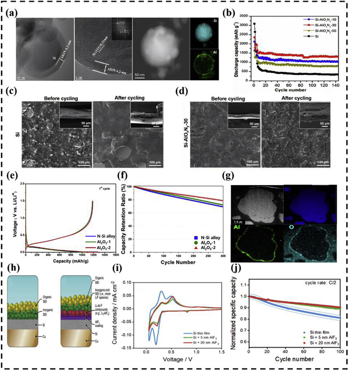
Fluoride layers can be used to inhibit electrolyte decomposition and promote the formation of a stable SEI [96-99]. Adhitama et al. evaluated how ALD-deposited aluminum fluoride (AlF3) coatings affected the SEI composition of silicon anodes [100]. A simplified diagram of the SEI is shown in Fig. 8h. Cyclic voltammetry (CV) results (Fig. 8i) indicated that the uncoated Si film exhibited a smaller current peak than the lithiation peak, suggesting poor reversibility. The electrochemical performance of electrodes with a higher LiF content was evaluated at a current rate of C/2 (1 C = 3000 mAh/g). AlF3-coated silicon films demonstrated a more stable and higher reversible capacity over 100 cycles compared with uncoated electrodes (Fig. 8j). The AlF3 coating alleviated volume expansion and facilitated the formation of a more stable SEI, which better protected the electrode against electrolyte-induced degradation during lithiation.
Molecular layer deposition (MLD) is a vapor-phase deposition technique for polymeric or hybrid thin films with excellent conformality and precise thickness control. The coatings can enhance the ion transport properties of materials while also serving as ion-conducting pathways to improve their intrinsic lithium intercalation/deintercalation capabilities, thereby significantly increasing the Coulombic efficiency. The inherent limitations of silicon anodes, particularly their low initial Coulombic efficiency (ICE) and interfacial stability, were addressed by Fang et al., who used ALD and MLD [101]. As shown in Fig. 9a, the methods were combined to construct an approximately 5 nm-thick Li2O-lithicone hybrid film on the silicon anode surface. Semi-quantitative analysis using time-of-flight secondary ion mass spectrometry (TOF-SIMS) revealed localized elemental enrichment in some interfacial regions. Comparative analysis with silicon's saturation sputtering time demonstrated that Si@Li2O-lithicone exhibited the thinnest SEI layer among the control groups. Fig. 9b shows that the fabricated electrode delivered a 91.2% initial Coulombic efficiency. The construction of organic/inorganic hybrid layers improved the initial Coulombic efficiency and increased the structural integrity of the material.
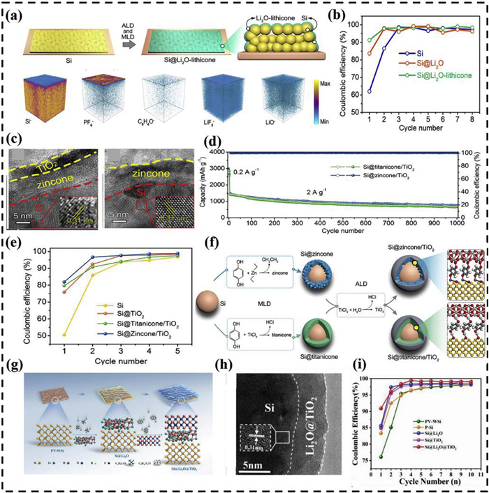
Fang et al. also used ALD to prepare a novel double-layer thin zinc manganese oxide/titanium dioxide film on a silicon electrode to enhance its electrochemical performance [102]. Transmission electron microscopy (TEM) observations revealed that the neck between silicon nanoparticles was connected through numerous zincone bridges (Fig. 9c). The Si@zincone/TiO2 electrode achieved an 81.9% ICE through its conformal bilayer coating, which minimized oxygen-containing groups and interfacial side reactions, thereby maintaining superior performance even at 2 A/g (Figs. 9d and e). This was attributed to a significant reduction in the irreversible consumption of lithium ions during the initial charge-discharge cycle due to the formation of an unstable, unevenly thick SEI film. Fig. 9f shows the synthesis of Si@zincone/TiO2 and Si@titanicone/TiO2. To develop silicon-based anodes that simultaneously show a high ICE and long-term stability, Wang et al. designed a dual-layered coating composed of Li2O and TiO2 via powder ALD (Fig. 9g) [103]. The rigid TiO2 inner layer maintained structural integrity during cycling while the Li2O outer layer mitigated lithium loss (Fig. 9h). The Si@Li2O@TiO2 composite achieved a record-breaking 90.9% ICE due to the lithium-supplying effect of Li2O (Fig. 9i) [104,105]. The core innovation is in the dual mechanism. The Li2O outer layer acted as an active lithium source during the initial charge/discharge process. It directly compensated for irreversible lithium loss caused by SEI formation and side reactions. The TiO2 inner layer further reduced lithium consumption by suppressing silicon volume expansion and forming a stable interface. This combination of active prelithiation and passive protection maximized the reversible utilization of lithium ions
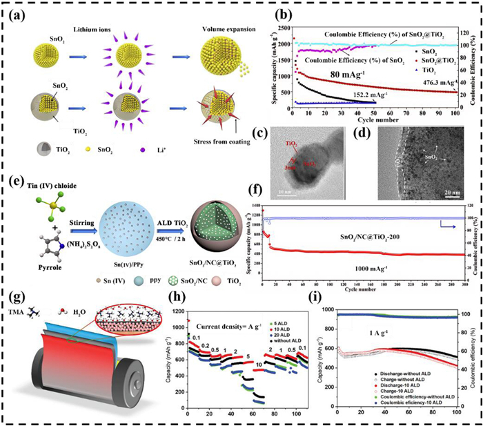
Tin-based anodes also suffer from severe volume changes due to alloying reactions, that significantly degrade the reversible capacity [106]. The limited reversibility of conversion reactions results in inferior initial Coulombic efficiency (ICE). The application of artificial surface layers with a high mechanical strength and ionic conductivity to nanostructured Sn-based materials can stabilize the SEI while maintaining a high capacity. TiO2 has superior mechanical robustness and enhanced ion diffusion and can improve the performance of anode coatings in lithium-ion batteries (LIBs). Chen et al. used ALD to fabricate core-shell SnO2@TiO2 nanostructures [107], as shown in Fig. 10a. The electrochemical performance demonstrated a significantly enhanced cycling stability compared with that of bare SnO2 due to the strain accommodation mechanism during lithiation/delithiation (Fig. 10b). The TiO2 layer uniformly encapsulated SnO2 nanoparticles, as evidenced by the micromorphology (Figs. 10c and d). To improve the structural integrity, Wei et al. used nitrogen-doped carbon as a substrate to prepare zinc-based anodes [108]. They achieved a dual-enhanced structure by embedding SnO2 into a nitrogen-doped carbon (NC) matrix, which was then coated with TiO2 (Fig. 10e). This hierarchical configuration significantly suppressed the volumetric effects of SnO2, achieving an initial discharge capacity of 1224 mAh/g, which remained at 871 mAh/g after 200 cycles at 100 mA/g (Fig. 10f). Al2O3 coatings have also been used to enhance the electrochemical performance of various LIB electrodes, including SnO2 [109], natural graphite [110], TiO2 [111], and Si [112]. Soltani et al. investigated the impact of Al2O3 thickness using 5, 10, or 20 ALD cycles on CoSn2 and Ni3Sn4 anodes [113]. They used ALD to directly apply an Al2O3 coating to an electrode composed of an intermetallic compound powder, a conductive carbon material, and a binder (Fig. 10g). The Al2O3-coated CoSn2 generated from 10 ALD cycles exhibited superior rate capability, delivering capacities of ≈ 290, 187, and 76 mAh/g at 2, 5, and 10 A/g, respectively (Figs. 10h and i). However, despite improved rate performance, the sample formed after 10 ALD cycles showed progressive capacity fading during prolonged cycling, retaining only ~600 mAh/g after 10 cycles at 0.1 A/g, indicating that while optimal Al2O3 thickness enhanced the kinetics, it alone did not completely suppress electrolyte degradation during extended operation.
The studies above have demonstrated that ALD provides exceptional thickness control and film density, which mitigates the substantial volume expansion inherent in alloy anodes and stabilizes the SEI structure. It also significantly suppresses electrolyte decomposition and parasitic side reactions, thereby enhancing the Coulombic efficiency. ALD enables the alternating deposition of functional coatings specifically designed to address the expansion issues and low initial Coulombic efficiency of alloying anodes [114,115]. However, stress generated by anisotropic expansion during the lithiation of alloy anodes imposes strict requirements on the coating thickness, where either an insufficient or excessive number of ALD layers may compromise the battery's performance [116,117]. Consequently, it is necessary to optimize the ALD parameters to stabilize alloy anodes and precisely control the thickness and enhance the electrochemical properties.
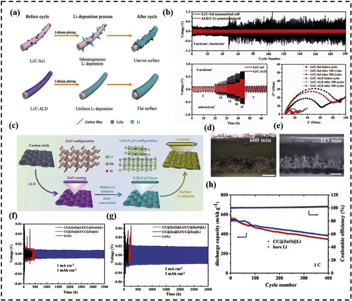
Lithium metal anodes are the main anodes for next-generation high-energy-density batteries (such as solid-state batteries, lithium-sulfur batteries, and lithium-air batteries). Their extremely high theoretical specific capacity and lowest electrochemical potential make them the key to breaking through current energy density limitations [118,119]. However, their interfacial instability prevents their further development [120,121]. Lithium anodes react with electrolytes to form a SEI that is ionically conductive but electronically insulating. Typically, the resulting SEI layer is heterogeneous with an uneven topography, which promotes disordered lithium nucleation and dendrite growth [122-124]. Lithium dendrites trigger continuous side reactions between lithium and electrolytes during cyclic plating/stripping, which generate electrochemically inactive dead Li while reducing the Coulombic efficiency. This irreversible process ultimately accelerates battery performance degradation [125]. The conformal coating of passivation layers that homogenize the electric field distribution across lithium metal surfaces using ALD suppresses dendrite growth while enhancing the cycling lifetime and safety of lithium-metal batteries. Zhao et al. employed ALD to deposit a uniform ZnO coating onto carbon fibers, followed by molten lithium infiltration to form Li/C-ALD anodes [126]. The lithiophilic ZnO layer achieved a highly uniform electron/ion distribution, resolving uneven lithium deposition through surface planarization (Fig. 11a). As shown in Fig. 11b, the ALD-derived ZnO provided homogeneous nucleation sites that facilitated spatially consistent Li plating and stabilized SEI formation, which collectively optimized the charge-transfer kinetics. Comparative rate capability tests (5.0–25 mA/cm2) demonstrated the superior performance of the ZnO-coated electrode compared with bare counterparts due to stabilized ion-transport pathways. The fabricated Li/C-ALD anode operated stably for 200 cycles at 5.0 mA/cm2 because ZnO suppressed the formation of dendritic Li and dead Li. This synergistic mechanism endowed the composite anode with exceptional cycling durability. The deposited passivation layer reduced the lithium nucleation overpotential, facilitating more favorable ion nucleation and deposition on the electrode surface [126]. Qian et al. uniformly deposited lithiophilic ZnO on carbon cloth (CC) and in situ generated LiZn/Li2O arrays to create a reliable and dendrite-free lithium metal anode through chemically constrained fabrication (Fig. 11c) [127]. In situ optical microscopy (Figs. 11d and e) revealed the morphological evolution during Li plating in which bare CC initiated dendrite growth at 113 min, while the modified CC@ZnO exhibited no dendrite formation even after 600 min. This stark contrast underscores the role of functional multiphase LiZn/Li2O in regulating uniform Li deposition and suppressing dendrite formation. CC@ZnO@Li symmetric cells maintained stable Li stripping/plating behavior (Figs. 11f and g), achieving cycling lifetimes that exceeded 3000 h. Even at high rates, the cells retained superior performance because ALD-engineered lithiophilic ZnO ensured a homogeneous Li+ flux and spatially controlled Li growth (Fig. 11h).
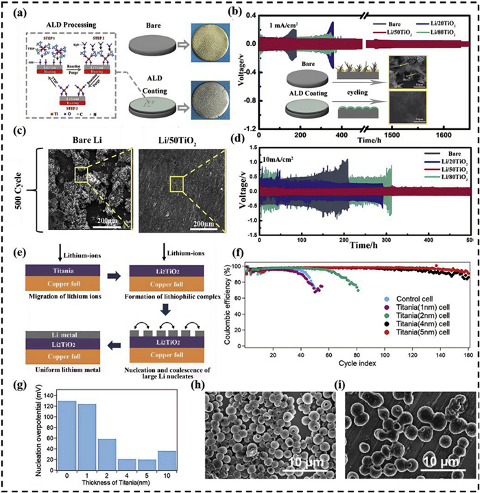
A conformal passivation layer facilitates uniform lithium deposition and suppresses parasitic side reactions. As shown in Fig. 12a, Wang et al. employed ALD to coat a lithium metal anode with an ultrathin TiO2 film [128]. The SEM images in the inset of Fig. 12b reveal clear morphological differences between bare lithium and Li/50TiO2 electrodes after 500 cycles, confirming the protective role of the TiO2 layer. Symmetric Li/50TiO2||Li/50TiO2 cells cycled stably for > 1600 h at both 1 mA/cm2 and 10 mA/cm2 due to suppressed lithium dendrite formation and preservation of the electrode integrity by the ALD-deposited TiO2 coating. Full-cell configurations with NCM622 cathodes showed a 23.3% higher in capacity retention after 100 cycles and cycled stably for over 500 h at a current density of 10 mA/cm2 (Figs. 12c and d). These results underscore the role of the TiO2 interfacial layer in promoting homogeneous lithium nucleation and mitigating excessive surface deposition. Oyakhire et al. similarly used TiO2 as a passivation layer and demonstrated that upon lithiation, TiO2 formed lithiophilic LixTiO2 [129]. This phase facilitated uniform and reversible lithium plating, which regulated the lithium nucleation morphology in ether-based electrolytes (Fig. 12e). When deposited on copper foil, the TiO2 coating acted as the nucleation layer for lithium metal, thereby reducing the nucleation overpotential and suppressing side reactions between lithium and the electrolyte. This reduced the consumption of active lithium. The TiO2 layer with a thickness of 5 nm yielded the lowest nucleation overpotential, indicating an optimal balance between surface lithiophilicity and structural integrity (Fig. 12f). This passivation layer prolonged the cycling lifespan and enhanced the lithium deposition reversibility. The lowest lithium nucleation overpotential was achieved when using a 5 nm TiO2 layer (Fig. 12g). SEM images revealed that lithium nuclei formed on uncoated copper were more concentrated and significantly larger than those formed on the pristine Cu foil due to the weak affinity between lithium atoms and the copper substrate, which failed to immobilize lithium nuclei during the early deposition stage (Figs. 12h and i).
Addressing these challenges requires advanced interface engineering strategies, such as ALD, which can be used to selectively prepare functional anodes by preventing lithium dendrite formation and the uneven deposition of lithium metal. The flexibility and adaptability of this method show great potential for modifying lithium-metal anode materials.
Due to growing demand for high-performance lithium batteries, atomic layer deposition (ALD) has emerged as a powerful tool to address interfacial instability in anode materials due to its exceptional capability for forming conformal and atomically-precise coatings. In intercalation-based anodes such as graphite and LTO, ultrathin ALD coatings can serve as uniform artificial interphases to enhance the interfacial ion transport and suppress parasitic reactions. For alloy-type anodes such as silicon, ALD-applied protective films (e.g., Al2O3, hybrid layers) mitigate pulverization and excessive SEI growth, thereby significantly improving the Coulombic efficiency. ALD-modified lithium metal anodes exhibit lower nucleation overpotentials, as well as suppressed dendrite growth and cycling durability through lithiophilic layers (e.g., ZnO, TiO2).
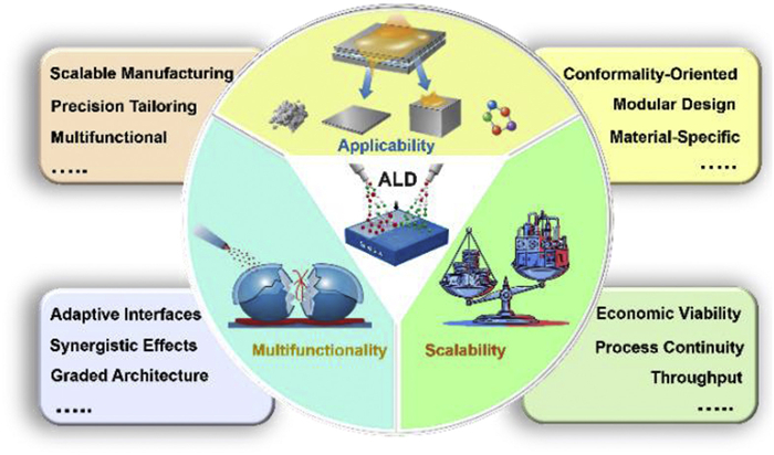
Despite these advances, challenges remain regarding the trade-off between interfacial protection and ion transport, especially for inorganic coatings that may react with lithium or increase resistance. As shown in Fig. 13, we envision the future of ALD from three perspectives: optimization of equipment, developing multifunctional coatings, and ensuring a continuous overall process. Specifically, future designs for ALD interfacial modification must account for the physical form (powder, planar electrode) and chemical properties of the anode to develop better-adapted equipment. Multifunctional coatings should be considered. Beyond unidimensional functions such as suppressing side reactions, mitigating volume expansion, or enhancing ion transport, coatings could also achieve self-healing capabilities. Finally, challenges to large-scale adoption include low deposition rates and batch-to-batch nonuniformity. The economic feasibility of continuous production (scalability and high efficiency) must also be addressed. This requires integrating structural design based on novel anode materials with the hardware architecture of ALD systems to create entirely new frameworks for incorporating ALD into lithium-battery anode production processes.
The authors declare that they have no known competing financial interests or personal relationships that could have appeared to influence the work reported in this paper.
Bin Wang: Writing – original draft. Zichuan Cheng: Visualization. Fengshuo Xi: Writing – review & editing, Funding acquisition, Conceptualization. Shaoyuan Li: Funding acquisition. Jijun Lu: Formal analysis. Xiuhua Chen: Validation. Wenhui Ma: Supervision.
This study was financially supported by the National Natural Science Foundation of China (Nos. 52474440, 52522410, 52204314, 52274408), Major Science and Technology Projects in Yunnan Province (No. 202402AF080005), Yunnan Fundamental Research Projects (Nos. 202201BE070001–002, 202201AW070014, 202201AT070442), Yunnan Xingdian Talents Support Plan (No. XDYC-QNRC-2022–0596), and the Program for Innovative Research Team in the University of Ministry of Education of China (No. IRT_17R48)
D.H. Liu, Z. Bai, M. Li, et al., Chem. Soc. Rev. 49 (2020) 5407–5445. doi: 10.1039/C9CS00636B
J. Li, Y. Cai, H. Wu, et al., Adv. Energy Mater. 11 (2021) 2003239. doi: 10.1002/aenm.202003239
L. Wang, J.L.F. Xi, et al., Adv. Energy Mater. 15 (2025) e03540. doi: 10.1002/aenm.202503540
X.Y. Zheng, L. Wang, F.S. Xi, et al., Rare Met. 44 (2025) 9763–9784. doi: 10.1007/s12598-025-03564-9
H. Zhao, X. Bo, H. Xu, et al., Energy Storage Mater. 72 (2024) 103696. doi: 10.1016/j.ensm.2024.103696
H. Liu, L. Wang, T. Qiao, et al., Int. J. Miner. Metall. Mater. 33 (2026) 657–668. doi: 10.1007/s12613-025-3250-3
L. Wang, J. Y, S. Li, et al., Energy Storage Mater. 66 (2024) 103243. doi: 10.1016/j.ensm.2024.103243
A. Kausar, Energ. Stor. Conv. 3 (2025) 2198. doi: 10.59400/esc2198
S. Chae, S.H. Choi, N. Kim, et al., Angew. Chem. Int. Ed. 59 (2020) 110–135. doi: 10.1002/anie.201902085
L. Zhao, B. Ding, X.Y. Qin, et al., Adv. Mater. 34 (2022) 2106704. doi: 10.1002/adma.202106704
Y. Shen, X. Shen, M. Yang, et al., Adv. Funct. Mater. 31 (2021) 2101181. doi: 10.1002/adfm.202101181
P. Luo, C. Zheng, J. He, et al., Adv. Funct. Mater. 32 (2022) 2107277. doi: 10.1002/adfm.202107277
Y. Li, Q. Li, J. Chai, et al., ACS Mater. Lett. 5 (2023) 2948–2970. doi: 10.1021/acsmaterialslett.3c00253
K. Wang, X.B. Zhong, Y.X. Song, et al., Rare Metals 43 (2024) 4948–4960. doi: 10.1007/s12598-024-02783-w
J. Liu, Y. Zhang, J. Zhou, et al., Adv. Funct. Mater. 33 (2023) 2302055. doi: 10.1002/adfm.202302055
S.R. Chen, F. Dai, M. Cai, ACS Energy Lett. 5 (2020) 3140–3151. doi: 10.1021/acsenergylett.0c01545
T. Li, M. Qu, G. Peng, et al., Chin. Chem. Lett. 37 (2026) 111310. doi: 10.1016/j.cclet.2025.111310
B. Li, Y. Chao, M. Li, et al., Electrochem. Energy Rev. 6 (2023) 7. doi: 10.1007/s41918-022-00147-5
H. Wu, H. Jia, C. Wang, et al., Adv. Energy Mater. 11 (2021) 2003092. doi: 10.1002/aenm.202003092
H. Cheng, J.G. Shapter, Y.Y. Li, et al., J. Energy Chem. 57 (2021) 451–468. doi: 10.1016/j.jechem.2020.08.056
L. Wang, Y. Jiang, S.Y. Li, et al., Rare Metals 42 (2023) 4091–4102. doi: 10.1007/s12598-023-02472-0
M.X. Wu, L.L. Su, S.Y. Sun, et al., Chin. Chem. Lett. 37 (2026) 111330. doi: 10.1016/j.cclet.2025.111330
Y. Zhao, J. Wang, Q. He, et al., ACS Nano 13 (2019) 5602–5610. doi: 10.1021/acsnano.9b00670
S. Karimzadeh, B. Safaei, C.S. Yuan, et al., Electrochem. Energy Rev. 6 (2023) 24. doi: 10.1007/s41918-023-00192-8
Y. Jin, H. Yu, X. Liang, Appl. Phys. Rev. 8 (2021) 031301. doi: 10.1063/5.0048337
S.J. Rajoba, A.N. Shirsat, D. Tyagi, et al., Mater. Lett. 285 (2021) 129134. doi: 10.1016/j.matlet.2020.129134
M. Salah, T. Pathirana, E. Alvarez de Eulate, et al., ACS Appl. Energy Mater. 4 (2021) 12243–12256. doi: 10.1021/acsaem.1c02035
E. Adhitama, F. Dias Brandao, I. Dienwiebel, et al., Adv. Funct. Mater. 32 (2022) 2201455. doi: 10.1002/adfm.202201455
E. Adhitama, M.M. Bela, F. Demelash, et al., Adv. Energy Mater. 13 (2023) 2203256. doi: 10.1002/aenm.202203256
G. Elomari, H. Larhlimi, R. Oubaki, et al., J. Power Sources 642 (2025) 236967. doi: 10.1016/j.jpowsour.2025.236967
J. Kim, Y.W. Cho, S.G. Woo, et al., Small 21 (2025) 2410570. doi: 10.1002/smll.202410570
S. Xiong, X. Qian, Z. Zhong, et al., J. Membrane Sci. 658 (2022) 120740. doi: 10.1016/j.memsci.2022.120740
B. Gupta, M.A. Hossain, A. Riaz, et al., Adv. Funct. Mater. 32 (2022) 2109105. doi: 10.1002/adfm.202109105
Y. Cao, X. Meng, A. Li, Energy Environ. Mater. 4 (2021) 363–391. doi: 10.1002/eem2.12132
M. Lee, W. Ahmad, D.W. Kim, et al., Chem. Mater. 34 (2022) 3539–3587. doi: 10.1021/acs.chemmater.1c02944
O. Bienek, B. Fuchs, M. Kuhl, et al., ACS Photonics 10 (2023) 3985–3987. doi: 10.1021/acsphotonics.3c00818
J.M. Gurrentz, K.A. Jarvis, I.R. Gearba-Dolocan, et al., Ultramicroscopy 239 (2022) 113562. doi: 10.1016/j.ultramic.2022.113562
J.P. Niemelä, B. Putz, G. Mata-Osoro, et al., ACS Appl. Nano Mater. 5 (2022) 6285–6296. doi: 10.1021/acsanm.2c00378
S.A. Tornoe, B. Cheney, B. Dupraw, et al., J. Astron. Telesc. Inst. 10 (2024) 044007.
I. Spajic, P. Rodi, G. Sekularac, et al., Electrochim. Acta 366 (2021) 137431. doi: 10.1016/j.electacta.2020.137431
X. Tian, Y.C. Ding, G.D. Chai, et al., Adv. Mater. Technol. 9 (2024) 2301541. doi: 10.1002/admt.202301541
N.Y. Kim, I. Kim, B. Bornamehr, et al., Energy Environ. Mater. 7 (2024) e12622. doi: 10.1002/eem2.12622
X. Wang, Z. Chen, S. Liu, et al., Energy Environ. Sci. 18 (2025) 2648–2667. doi: 10.1039/D4EE06107A
B. Chen, L. Chen, L. Zu, et al., Adv. Mater. 34 (2022) 2200894. doi: 10.1002/adma.202200894
Q. Ouyang, G.S. Li, X. Zhang, et al., Chem. Eng. J. 460 (2023) 141762. doi: 10.1016/j.cej.2023.141762
Y.L. Liu, L. Ma, J.R. Dahn, J. Electrochem. Soc. 168 (2021) 080537. doi: 10.1149/1945-7111/ac1eb7
T. Nakamura, A. Maekawa, K. Ariyoshi, Electrochim. Acta 439 (2023) 141731. doi: 10.1016/j.electacta.2022.141731
X. Guan, K.C. Chan, L. Lei, et al., Electrochim. Acta 469 (2023) 143247. doi: 10.1016/j.electacta.2023.143247
Z. Wang, M. Yao, H. Luo, et al., Small 20 (2024) 2306428. doi: 10.1002/smll.202306428
S. Kim, D.Y. Han, G. Song, et al., Chem. Eng. J. 473 (2023) 145441. doi: 10.1016/j.cej.2023.145441
E.J. Moon, J.K. Hong, S.K. Mohanty, et al., J. Power Sources 559 (2023) 232657. doi: 10.1016/j.jpowsour.2023.232657
Y.S. Feng, Y.N. Li, P. Wang, et al., Angew. Chem. Int. Ed. 62 (2023) e202310132. doi: 10.1002/anie.202310132
Y. Han, B. Liu, Z. Xiao, et al., InfoMat 3 (2021) 155–174. doi: 10.1002/inf2.12166
S.J. Lu, Y.X. Zhang, X.Y. Zhang, et al., Chem. Eng. J. 507 (2025) 160455. doi: 10.1016/j.cej.2025.160455
H. Tian, M. Graczyk-Zajac, A. Kessler, et al., Adv. Mater. 36 (2024) 2308494. doi: 10.1002/adma.202308494
T. Acharya, A.D. Pathak, S. Pati, J. Energy Storage 67 (2023) 107529. doi: 10.1016/j.est.2023.107529
M. Su, Y. Chen, S. Wang, et al., Chin. Chem. Lett. 34 (2023) 107553. doi: 10.1016/j.cclet.2022.05.067
R.L. Puurunen, Chem. Vap. Deposition 20 (2014) 332–344. doi: 10.1002/cvde.201402012
F. Lantelme, A. Mantoux, H. Groult, et al., J. Electrochem. Soc. 150 (2003) A1202–A1208. doi: 10.1149/1.1595658
Y.S. Jung, A.S. Cavanagh, L.A. Riley, et al., Adv. Mater. 22 (2010) 2172. doi: 10.1002/adma.200903951
X.C. Xiao, P. Lu, D. Ahn, Adv. Mater. 23 (2011) 3911–3915. doi: 10.1002/adma.201101915
E. Kazyak, K.N. Wood, N.P. Dasgupta, Chem. Mater. 27 (2015) 6457–6462. doi: 10.1021/acs.chemmater.5b02789
G. Wang, M. Yu, X. Feng, Chem. Soc. Rev. 50 (2021) 2388–2443. doi: 10.1039/D0CS00187B
X. Sun, H. Liu, K.F. Ren, et al., Small 20 (2024) 2401675. doi: 10.1002/smll.202401675
H. Chang, Y.R. Wu, X. Han, et al., Energy Mater. 1 (2021) 100003.
Y. Liu, H. Shi, Z.S.J.E. Wu, et al., Energy Environ. Sci. 16 (2023) 4834–4871. doi: 10.1039/D3EE02213G
H. Zhang, Y. Yang, D. Ren, et al., Energy Storage Mater. 36 (2021) 147–170. doi: 10.1016/j.ensm.2020.12.027
B. Zhao, A. Dhara, J. Dendooven, et al., Front. Energy Res. 8 (2020) 609417. doi: 10.3389/fenrg.2020.609417
Z.L. Jian, W.T. Wang, M.Y. Wang, et al., Chin. Chem. Lett. 29 (2018) 1768–1772. doi: 10.1016/j.cclet.2018.11.002
G.L. Wu, K.K. Cheong, W.J. Lee, et al., J. Energy Storage 73 (2023) 108951. doi: 10.1016/j.est.2023.108951
A. Helaley, H. Yu, X.J.E.A. Liang, Energy Adv. 4 (2025) 249–261. doi: 10.1039/D4YA00518J
D. Wang, Y. Li, Y. Zhao, et al., Nanoscale Res. Lett. 14 (2019) 1–7.
H. Zhao, H. Gao, B. Li, et al., Mater. Lett. 252 (2019) 215–218. doi: 10.1016/j.matlet.2019.05.059
W. Mao, W. Yue, Z. Xu, et al., ACS Appl. Mater. Inter. 12 (2020) 39282–39292. doi: 10.1021/acsami.0c11282
P.P. Sahoo, A. Güneren, B. Hudec, et al., ACS Appl. Nano Mater. 7 (2024) 18486–18498. doi: 10.1021/acsanm.3c05066
T. Zhu, C. Yu, Y. Li, et al., J. Colloid Interface Sci. 585 (2021) 574–582. doi: 10.1016/j.jcis.2020.10.037
Y. Jin, H. Yu, Y. Gao, et al., J. Power Sources 436 (2019) 226859. doi: 10.1016/j.jpowsour.2019.226859
Y. Jin, H. Yu, Y. Gao, et al., Meet. Abstr. MA 2020-01 (2020) 377.
J.K. Yoon, S. Nam, H.C. Shim, et al., Materials 11 (2018) 803. doi: 10.3390/ma11050803
J. Speulmanns, A.M. Kia, S. Bönhardt, et al., Small 17 (2021) 2102635. doi: 10.1002/smll.202102635
J. Speulmanns, S. Bönhardt, W. Weinreich, et al., Small 20 (2024) 2403453. doi: 10.1002/smll.202403453
C. Tang, Z. Qiu, C. Li, et al., Chin. Chem. Lett. 36 (2025) 110589. doi: 10.1016/j.cclet.2024.110589
G.G. Eshetu, H. Zhang, X. Judez, et al., Nat. Commun. 12 (2021) 5459. doi: 10.1038/s41467-021-25334-8
Z.D. Chen, A. Soltani, Y.G. Chen, et al., Adv. Energy Mater. 12 (2022) 2200924. doi: 10.1002/aenm.202200924
H. Zhao, J. Li, Q. Zhao, et al., Electrochem. Energy Rev. 7 (2024) 11. doi: 10.1007/s41918-024-00214-z
Y. Zhang, J. Wang, Z. Xue, Adv. Funct. Mater. 34 (2024) 2311925. doi: 10.1002/adfm.202311925
W. He, W. Xu, Z. Li, et al., Adv. Sci. 12 (2025) 2407540. doi: 10.1002/advs.202407540
W. Li, Y. Xu, G. Wang, et al., Adv. Energy Mater. 14 (2024) 2403593. doi: 10.1002/aenm.202403593
P. Zhou, P. Xiao, L. Pang, et al., Adv. Funct. Mater. 35 (2025) 2406579. doi: 10.1002/adfm.202406579
M.Y. Jin, K. Guo, X.C. Xiao, et al., Adv. Funct. Mater. 31 (2021) 2010640. doi: 10.1002/adfm.202010640
Y.W. Zhang, X.T. Li, Y. Zhang, et al., J. Alloys Compd. 968 (2023) 171831. doi: 10.1016/j.jallcom.2023.171831
J. Fang, K. Wu, L. Qin, et al., Small 21 (2025) 2504940. doi: 10.1002/smll.202504940
H.Z. Zhu, M.H.A. Shiraz, L. Liu, et al., Appl. Surf. Sci. 578 (2022) 151982. doi: 10.1016/j.apsusc.2021.151982
Y. Feng, R. Tao, K. Livingston, et al., J. Energy Storage 100 (2024) 113711. doi: 10.1016/j.est.2024.113711
K. Lee, S. Yoon, S. Hong, et al., Materials 15 (2022) 4189. doi: 10.3390/ma15124189
J. Chen, X. Fan, Q. Li, et al., Nat. Energy 5 (2020) 386–397. doi: 10.1038/s41560-020-0601-1
Z. Shadike, H. Lee, O. Borodin, et al., Nat. Nanotechnol. 16 (2021) 549–554. doi: 10.1038/s41565-020-00845-5
Z. Li, L. Wang, X. Huang, et al., Small 20 (2024) 2305429. doi: 10.1002/smll.202305429
J. Tan, J. Matz, P. Dong, et al., Adv. Energy Mater. 11 (2021) 2100046. doi: 10.1002/aenm.202100046
E. Adhitama, S. Van Wickeren, K. Neuhaus, et al., Adv. Energy Mater. 12 (2022) 2201859. doi: 10.1002/aenm.202201859
J. Fang, J. Li, L. Qin, et al., J. Am. Chem. Soc. 15 (2023) 27963–27974.
J.B. Fang, Y.Q. Cao, S.Z. Chang, et al., Adv. Funct. Mater. 32 (2022) 2109682. doi: 10.1002/adfm.202109682
L. Wang, J.J. Lu, S.Y. Li, et al., Adv. Funct. Mater. 34 (2024) 2403574. doi: 10.1002/adfm.202403574
S. Lorger, K. Narita, R. Usiskin, et al., Chem. Commun. 57 (2021) 6503–6506. doi: 10.1039/D1CC00557J
H. Li, Z. Wang, L. Dang, et al., Small 20 (2024) 2307722. doi: 10.1002/smll.202307722
H. Zhang, L. Wang, T. Lu, et al., ACS Appl. Nano Mater. 7 (2024) 3239–3248. doi: 10.1021/acsanm.3c05590
H. Chen, Y. Lu, H. Zhu, et al., Electrochim. Acta 310 (2019) 203–212. doi: 10.1016/j.electacta.2019.04.134
D. Wei, S. Zhong, H. Zhang, et al., Electrochim. Acta 290 (2018) 312–321. doi: 10.1016/j.electacta.2018.08.094
G. Wu, R. Zhang, S. Chen, et al., Ionics 29 (2023) 2217–2225. doi: 10.1007/s11581-023-04974-4
S.M. Gowdru, Y.C. Wu, T.R. Liu, et al., J. Chin. Chem. Soc. 70 (2023) 2238–2244. doi: 10.1002/jccs.202300291
H. Sopha, G. Salian, R. Zazpe, et al., Meet. Abstr. MA 2017-02 (2017) 351.
J. Li, R. Zhao, X. Wang, Nanotechnology 34 (2023) 245708. doi: 10.1088/1361-6528/acc408
N. Soltani, S.M. Abbas, M. Hantusch, et al., Adv. Mater. Interfaces 9 (2022) 2201598. doi: 10.1002/admi.202201598
C. Yang, Y. Li, X. Zhang, et al., Ionics 28 (2022) 4547–4554. doi: 10.1007/s11581-022-04691-4
K. Seong, K. Lee, S.H. Yoon, et al., Thin Solid Films 817 (2025) 140656. doi: 10.1016/j.tsf.2025.140656
S. Pakseresht, V. Miikkulainen, F.A. Obrezkov, et al., J. Power Sources 653 (2025) 237731. doi: 10.1016/j.jpowsour.2025.237731
Y. Li, Y. Zhao, G. Huang, et al., ACS Appl. Mater. Inter. 9 (2017) 38522–38529. doi: 10.1021/acsami.7b11735
S.Y. Sun, X.Q. Zhang, X.Y. Yan, et al., EES Batter. 1 (2025) 340–363. doi: 10.1039/D4EB00034J
S. Kalnaus, N.J. Dudney, A.S. Westover, et al., Science 381 (2023) eabg5998. doi: 10.1126/science.abg5998
O.B. Chae, B.L. Lucht, Adv. Energy Mater. 13 (2023) 2203791. doi: 10.1002/aenm.202203791
Z. Zheng, X. Liu, X.Q. Zhang, et al., Angew. Chem. Int. Ed. 64 (2025) e202507387. doi: 10.1002/anie.202507387
T. Wei, J. Lu, P. Zhang, et al., Chin. Chem. Lett. 34 (2023) 107947. doi: 10.1016/j.cclet.2022.107947
L.X. Li, Y.X. Li, Y.S. Feng, et al., Natl. Sci. Rev. 12 (2025) nwaf305. doi: 10.1093/nsr/nwaf305
H. Ye, Z.J. Zheng, H.R. Yao, et al., Angew. Chem. Int. Ed. 58 (2019) 1094–1099. doi: 10.1002/anie.201811955
Q. Wang, T.T. Lu, Y.B. Xiao, et al., Electrochem. Energy Rev. 6 (2023) 22. doi: 10.1007/s41918-023-00185-7
B. Zhao, B.B. Li, Z.X. Wang, et al., ACS Appl. Mater. Inter. 12 (2020) 19530–19538. doi: 10.1021/acsami.0c02153
H. Qian, X. Li, Q. Chen, et al., Adv. Funct. Mater. 34 (2024) 2310143. doi: 10.1002/adfm.202310143
M. Wang, X. Cheng, T. Cao, et al., J. Alloy Compd. 865 (2021) 158748. doi: 10.1016/j.jallcom.2021.158748
S.T. Oyakhire, W. Huang, H. Wang, et al., Adv. Energy Mater. 10 (2020) 2002736. doi: 10.1002/aenm.202002736

Figure 3 The development history of atomic layer deposition and its application in lithium-ion battery anodes. Reproduced with permission [59]. Copyright 2003, Electrochemical Society, Inc. Reproduced with permission [60]. Copyright 2010, Wiley. Reproduced with permission [61]. Copyright 2011, Wiley. Reproduced with permission [62]. Copyright 2015, American Chemical Society.

Figure 4 (a, b) SEI layer on the MGP electrode of the 11 nm and 0 nm A-TiO2-coated sample before and after cycling. (c) Cycling performance of the sample cells with electrodes with 0, 1, 3, 5, 7, 9, and 11 nm A-TiO2 coatings. (d) Capacities and capacity retention rates of sample cells with electrodes with various A-TiO2 coatings after the 230th ALD cycle. (e) EDS map of the MGP electrode. Reproduced with permission [70]. Copyright 2023, Elsevier. (f) Peak current vs. the square root of the scan rate of graphite electrodes. (g, h) Cycling and rate performance of a graphite electrode. Reproduced with permission [71]. Copyright 2025, Royal Society of Chemistry. (i) Fabrication schematic of GAZ composites. (j-k) Rate and cycling performance of pure GA and GAZ. Reproduced with permission [72]. Copyright 2019, Springer.

Figure 5 (a, b) SEM image of NG and NG-V nanosheets. (c) Rate performance and capacity. Reproduced with permission [73]. Copyright 2019, Elsevier. (d) Novel Hoberman sphere design for the interlaced Mn3O4@CNT architecture with ALD-coated TiO2. (e) TEM and HRTEM images of Mn3O4@CNT/TiO2 composite. (f-g) Cycling performance and rate performance of Mn3O4/CNT, Mn3O4@CNT, and Mn3O4@CNT/TiO2. Reproduced with permission [74]. Copyright 2020, American Chemical Society. (h, i) Cycling performance and rate performance of pristine and ZnO-coated Si/Gr anodes. Reproduced with permission [75]. Copyright 2024, American Chemical Society.

Figure 6 (a) TEM image of a 250–10AZO particle. (b) Cycling performance of UC LTO and the AZO-coated LTO samples. (c) Rate performance of UC LTO and the AZO-coated LTO samples. Reproduced with permission [77]. Copyright 2019, Elsevier. (d) Schematic diagram of the LTO electrode. (e) EDS element maps of Al2O3-coated LTO electrode. (f) Cycle-life performance of Al2O3-coated and uncoated LTO. Reproduced with permission [79]. Copyright 2018, MDPI.

Figure 7 (a) Schematic illustration of ALD Li4Ti5O12 thin films. (b) Long-term cycling performance of ALD Li4Ti5O12 at 100 C. Reproduced with permission [80]. Copyright 2021, Wiley. (c) 3D architecture of a silicon substrate with LTO deposition via ALD. (d) Areal capacity and cycling stability of the Li4Ti5O12 thin films on 3D substrates. Reproduced with permission [81]. Copyright 2024, Wiley. (e) Schematic diagram of N-doped LTO (N-LTO) on vertical graphene (VG). (f) Ultra-stable cycling performance of TiN@N-LTO. Reproduced with permission [82]. Copyright 2024, Elsevier.

Figure 8 (a) TEM, HRTEM, and STEM images and EDX maps of Si particles with an AlOxNy coating deposited over 100 ALD cycles. (b) Cycling stability of the Si electrode coated with AlOxNy layers formed by 10, 30, and 50 ALD cycles. (c, d) Top-view and cross-sectional SEM images of pristine Si electrode and Si-AlOxNy-30 electrodes. Reproduced with permission [93]. Copyright 2022, Elsevier. (e) The first cycle for N-Si alloy, Al2O3–1, and Al2O3–2 during lithiation/delithiation. (f) Cycling performance of N-Si alloy, Al2O3–1, and Al2O3–2. (g) Cross-sectional S/TEM-EDS images of the Al2O3–2 powder. Reproduced with permission [95]. Copyright 2022, MDPI. (h) Schematic illustrations of the SEI on uncoated Si and coated Si electrodes. (i, j) Cyclic voltammetry profiles and cycle number profiles of Si, Si + 5 nm AlF3 and Si + 20 nm AlF3. Reproduced with permission [100]. Copyright 2022, Wiley.

Figure 9 (a) Schematic of the fabrication of the Si@Li2O-lithicone electrode and TOF-SIMS. (b) Coulombic efficiency during the first eight cycles. Reproduced with permission [101]. Copyright 2023, American Chemical Society. (c, d) SEM and TEM images and cycling performance of Si@titanicone/TiO2 and Si@zincone/TiO2. (e) Coulombic efficiency during the first five cycles. (f) Schematic illustration of the synthetic procedure. Reproduced with permission [102]. Copyright 2022, Wiley. (g) Schematic diagram of the synthesis of Si@Li2O@TiO2. (h) TEM images of Si@Li2O@TiO2. (i) Coulombic efficiency for the first ten cycles. Reproduced with permission [103]. Copyright 2024, Wiley.

Figure 10 (a) Schematic diagram of volume changes in SnO2 and SnO2@TiO2. (b) Cycling performance of SnO2, TiO2 and SnO2@TiO2. (c) TEM image of SnO2@TiO2. Reproduced with permission [107]. Copyright 2019, Elsevier. (d) SEM image of SnO2/NC@SnO2–200. (e) Synthesis procedure for SnO2/NC@TiO2. (f) Long-term cycling performance of SnO2/NC@TiO2–200. Reproduced with permission [108]. Copyright 2018, Elsevier. (g) Schematic of Al2O3 coating on anode layer. (h, i) Comparison of rate capability and long-term cycling stability. Reproduced with permission [113]. Copyright 2022, Wiley.

Figure 11 (a) Diagram of Li deposition in Li/C-Sol and Li/C-ALD. (b) Voltage profiles, rate, and EIS performance of Li/C-Sol and Li/C-ALD symmetrical cells. Reproduced with permission [126]. Copyright 2020, American Chemical Society. (c) Schematic illustration of the CC@ZnO@Li anode. (d, e) In situ optical observation of lithium deposition. (f, g) Galvanostatic cycling, rate performance of CC@ZnO@Li//CC@ZnO@Li, CC@Zn@Li//CC@Zn@Li and Li//Li cells. (h) Long-term cycling stability of a Li-S battery with bare Li and CC@ZnO@Li. Reproduced with permission [127]. Copyright 2024, Wiley.

Figure 12 (a, b) Schematic diagram and photos of an ultrathin TiO2 layer formed by ALD. (c) Electrochemical cycling curves of a Li||NCM622 battery with bare Li and Li/50TiO2. (d) Galvanostatic charge-discharge tests of Li/20TiO2, Li/50TiO2, Li/80TiO2, and the bare Li symmetric battery. Reproduced with permission [128]. Copyright 2021, Elsevier. (e) Schematic illustration of the role of TiO2 acting as a nucleation layer for electrodeposited lithium. (f) Coulombic efficiency of Li/Cu cells cycled with 1, 2, 4, and 5 nm-thick TiO2 layers. (g) Nucleation overpotential for layers of TiO2 with different thicknesses during the first cycle. (h, i) SEM images of lithium nuclei formed in the control cell and 5 nm TiO2 cell, respectively. Reproduced with permission [129]. Copyright 2020, Wiley.

Figure 13 Outlook and future perspectives for the development of ALD in lithium battery anodes.
Table 1. Comparison of different surface coating methods in terms of their advantages, disadvantages, and suitable anode types.
| Method | Spin coating | Evaporation | Sol–gel | Physical vapor deposition (PVD) | Chemical vapor deposition (CVD) | Atomic layer deposition (ALD) |
| Advantages | Simple operation, low cost, suitable for rapid preparation of flat films | High deposition rate, high film purity, simple process | High adhesive strength, low cost, simple to perform | Relatively fast process, low temperature, low cost | High growth rate, simple, various precursor availability | Superior conformality and uniformity, atomic-level thickness control, excellent stability, low-temperature process, diverse chemistry |
| Challenges | Poor conformality, high material waste, empirical thickness control | Difficult composition control, poor adhesion | Nonuniform deposition, certain crystal phases require, high-temperature annealing | Slow deposition rate, impurities, small area deposition | High temperature, limited film types | Slow deposition rate, complex equipment, high cost for mass production |
| Suitable anode types | Only suitable for model studies | Primarily used for metal anodes | Most anodes | Electrodes with flat surfaces | Most anodes | All high-performance and nanostructured anodes |
 下载: 导出CSV
Table 2. Overview of lithium battery anode materials prepared by ALD.
| Material | ALD strategy | Optimum thickness | ICE (%) | Capacity retention rate | Ref. |
| MGP@TiO2 | A-TiO2 | 11 nm | 92.1 | 230 cycles at 0.1 C maintain 334.3 mAh/g | [70] |
| 2Zn-Graphite | ZnO | 2 cycles | > 92 | 500 cycles at 0.2 C maintain ~420 mAh/g | [71] |
| GAZ100 | ZnO | ~5 nm | —— | 1000 cycles at 1A/g maintain ~1000 mAh/g | [72] |
| NG-V | V2O5 | 5 nm | ~69 | 500 cycles at 1A/g maintain 365 mAh/g | [73] |
| Mn3O4@CNT/TiO2 | TiO2 | ~3 nm | ~90 | 200 cycles at 0.2 A/g maintain 740.7 mAh/g | [74] |
| Si-Gr | ZnO | 3.4nm | 65.7 | 140 cycles at 1 C maintain 285 mAh/g | [75] |
| 250–10AZO | Al-doped ZnO (AZO) | ~2.5 nm | —— | 100 cycles at 5 C maintain ~159 mAh/g | [77] |
| LTO | Al2O3 | ~2 nm | > 90 | Outstanding 98% capacity retention after 500 cycles | [79] |
| ALD Li4Ti5O12 | LTO | ~30 nm | > 95 | Outstanding 97.9% capacity retention after 1000 cycles | [80] |
| ALD Li4Ti5O12 | LTO | 50 nm | 99.9975 | Outstanding 97.5% capacity retention after 1000 cycles | [81] |
| TiN@N-LTO | LTO | — | > 90 | Capacity retention of 99.6% after 5000 cycles at 10 C | [82] |
| Si-AlOxNy-30 | AlOxNy | 30 cycles | 67 | 140 cycles at 0.1 C maintain 1297 mAh/g | [93] |
| Al2O3–2 | Al2O3 | ~30 nm | 92.5% | 300 cycles at 0.1 C maintain 1013 mAh/g | [95] |
| Si + 20 nm AlF3 | AlF3 | 5 nm, 20 nm | 70.6 | 100 cycles at 0.5 C maintain ~3157 mAh/g | [100] |
| Si@Li2O-lithicone | Li2O-lithicone | ~5 nm | 91.2 | 850 cycles at 2 A/g maintain 646 mAh/g | [101] |
| Si@zincone/TiO2 | zincone/ TiO2 | ~5 nm | 81.9 | 1000 cycles at 2 A/g maintain 753 mAh/g | [102] |
| Si@Li2O@TiO2 | Li2O@TiO2 | Li2O (~1 nm), TiO2 (~4 nm) | 90.9 | 1150 cycles at 2 A/g maintain 1300 mAh/g | [103] |
| SnO2@TiO2 | TiO2 | ~3 nm | ~65 | 100 cycles at 0.08A/g maintain 1259 mAh/g | [107] |
| SnO2/NC@TiO2 | TiO2 | 10nm | 72.3 | 200 cycles at 1 A/g maintain ~869 mAh/g | [110] |
| CoSn2 and Ni3Sn4 | Al2O3 | 10 cycles | ~99 and ~100 | 100 cycles at 1 A/g maintain ~400 and ~300 mAh/g | [113] |
| Li/C-ALD | ZnO | 50 nm | —— | Ultra-long lifespan of 400 cycles at 3.0 mA/cm2 | [126] |
| LiZn/Li2O | ZnO | —— | —— | Cycle life exceeding 3000 h at 3 mA/cm2 | [127] |
| Li/50TiO2 | TiO2 | 50 nm | —— | Stable cycling for over 500 h at 10 mA/cm2 | [128] |
| Titania (5 nm) cell | TiO2 | 5 nm | —— | Stable cycling for over 150 cycles at 1 mA/cm2 | [129] |
下载: 导出CSV

 扫一扫看文章


扫一扫关注我们


 下载:
下载: