National Engineering Research Center of Vacuum Metallurgy, Faculty of Metallurgical and Energy Engineering, Kunming University of Science and Technology, Kunming 650093, China
Received Date:
14 July 2025 Accepted Date:
12 October 2025 Revised Date:
03 October 2025 Available Online:
15 August 2026
Abstract:
Due to the abundant potassium resources, potassium ion batteries (PIBs) are gradually becoming a promising choice for large-scale energy storage. Among the many anode materials that have been investigated, antimony anode has attracted much attention due to its high theoretical specific capacity, low reaction potential and high electrical conductivity. However, these antimony anodes undergo significant volume changes (≈407%) during the potassium alloying reaction, which negatively affect their cycle stability and rate performance. In this paper, the research progress of antimony anodes in recent years is reviewed. Modification strategies to improve the performance of antimony anodes, including architectural design, alloying with other metals, composite system construction and electrolyte optimization, are discussed in depth. In addition, the possible future development directions for antimony anodes in PIBs with a view to accelerating their practical application are proposed. It is hoped that this review will help researchers design high-performance antimony anode materials more efficiently.
Nowadays, with the rapid advancement of new energy vehicles and large-scale energy storage systems, the pursuit of cost-effective, high-energy density and high-safety battery systems has become the main direction for future exploration and research [1–3]. For the past few years, lithium-ion batteries (LIBs) have been widely adopted across numerous fields, such as portable electronic devices, power systems for electric vehicles, and energy storage solutions for photovoltaic and wind power applications [4–6]. The scarcity of lithium resources and high processing costs have hindered its further development in large-scale energy storage and battery industry applications that require inexpensive raw materials and efficient preparation and processing [7–9]. Based on the dual considerations of resource sustainability and economic feasibility, the construction of secondary battery systems (sodium ion/potassium ion batteries) with the potential for large-scale application has become a key research direction to break through the dilemma of energy density-cost trade-offs of the existing energy storage technologies, which is of strategic significance for realizing the goal of carbon neutrality [10–12]. Potassium, lithium and sodium, as group IA alkali metal elements, determine that the three exhibit similar embedding/deembedding behaviors and electrode reaction kinetics in electrochemical energy storage systems [13,14]. A comparison of the crustal abundance, redox potential, and Shannon ionic radius properties of the Potassium, lithium, and sodium elements is shown in Fig. 1a. As a result, potassium ion batteries (PIBs) offer several key advantages: (1) PIBs possess higher operating voltages and higher energy density because the standard redox potentials of K+/K (−2.93 V) are lower than those of Na+/Na (−2.71 V) and are nearer to Li+/Li (−3.04 V) [15–18] (2) K+ has a high ionic conductivity in the electrolyte due to the fact that K+ has a lower charge density than Na+ and Li+, and so gives rise to smaller solvated ions and weaker potassium desolvation energy [19]; (3) PIBs can directly use graphite as a negative electrode with the formation of KC8 compounds [20]. Therefore, PIBs have promising application in future energy storage.
Figure 1
Figure 1.
Optimization strategies for antimony anodes for PIBs. (a) Comparison of radar charts for the three metals lithium, sodium and potassium (each axis is independent). (b) Schematic of the approach to enhance Sb anode electrochemical performance in PIBs.
Several critical challenges remain in the advancement of PIBs. Firstly, the substantial ionic radius of potassium ions has the capacity to induce considerable structural deformation in electrode materials during the processes of intercalation and deintercalation [21]. Second, the relatively slow rate of movement of potassium ions is a limiting factor in rate capability [22]. In 2015, research revealed that while commercial graphite, employed as an anode material, delivers a specific capacity of 273 mAh/g, it exhibited a substantial volume expansion of up to 61% during potassium storage. This phenomenon led to rapid capacity degradation [23,24]. To address these limitations, researchers are developing advanced anode materials, including carbon-based [25–27], alloy-based materials [28–30], conversion-type materials [31,32], and organic compounds [33,34], aiming to substantially enhance PIBs electrochemical performance.
Antimony (Sb) anodes have garnered significant interest as promising battery materials, owing to their 660 mAh/g theoretical capacity (creation of K3Sb alloy phase) [35], suitable operating potential, and environmental sustainability. Compared to graphite carbon materials, Sb anodes not only exhibit high theoretical specific capacity but also possess a unique wrinkled layered structure with low packing density [36]. Furthermore, compared with other metal anodes (such as Bi, Ge and Pb), antimony has higher electrical conductivity, and the formation of K3Sb can store more charge (Table 1) [37]. Antimony's facile nanostructuring capability endows it with distinctive advantages for enhancing potassium-ion battery performance compared to phosphorus and silicon. On one hand, it significantly improves K+ transport kinetics, enabling superior rate capability [18]; on the other hand, it effectively mitigates electrode polarization during (dis)charge processes, substantially boosting coulombic efficiency [38]. Additionally, its safe operating potential range not only addresses the safety concerns associated with metallic potassium anodes but also creates favorable conditions for improving battery energy density. However, Sb anode materials undergo approximately 407% volume expansion during the alloying-type potassium storage process, which triggers active material aggregation and electrode structure pulverization [39]. Coupled with unstable electrode/electrolyte interfaces, these issues ultimately lead to rapid specific capacity fading, shortened cycle life, and deteriorated rate performance [40]. It is evident that these critical challenges impose significant constraints on the practical application of Sb anode materials in PIBs.
Table 1
Table 1.
The alloys and their associated theoretical specific capacities in commonly utilized alloy-based anodes for PIBs [37].
To address these challenges, researchers have developed a series of innovative solutions and achieved remarkable breakthroughs, primarily including: Nanostructure regulation, heterointerface engineering, carbon-based composite system construction, and electrolyte composition optimization. Although several recent reviews have reported progress in antimony materials for PIBs, there remains a notable gap in systematic summaries of the intrinsic characteristics, potassium storage mechanism advantages, and modification strategies of Sb anode materials [19,37,41–43]. This review offers an extensive overview of the most recent advancements in antimony anode materials research. Focusing on current challenges, the report highlights structural and morphological design, alloying strategies, composite system construction, and electrolyte optimization while elucidating the benefits of various modification approaches to improve K storage behavior (Fig. 1b). Furthermore, this review outlines the current challenges, and potential future developments in the field of high-performance Sb anode materials for PIBs. This work provides valuable insights for research on Sb anode materials and offers important theoretical guidance and technical references for designing next-generation anode materials for PIBs.
2.
Potassium storage mechanism in antimony anodes
Antimony, an environmentally friendly yet brittle metal, has garnered significant attention as a promising anode material for PIBs due to its high theoretical capacity and suitable operating potential. Therefore, it is important to study the working mechanism of antimony anode materials for PIBs, and the products of charging and discharging at various stages to guide the design and strategies to improve their electrochemical performance. At present, the potassium storage mechanism for antimony anodes is mainly based on the alloying-dealloying mechanism (Fig. 2). However, different antimony anode materials have different alloy phases KxSb (KSb2, KSb, K5Sb4, and K3Sb).
Figure 2
Figure 2.
The Development of potassium storage mechanism in antimony anodes of PIBs. Propose the antimony/potassium system. Reprinted with permission [68]. Copyright 2018, American Chemical Society. The alloy-dealloying process. Reprinted with permission [55]. Copyright 2019, Elsevier B.V. Confirmed the alloy-de-alloying mechanism. Reprinted with permission [86]. Copyright 2020, Wiley-VCH. The working principle of full battery. Reprinted with permission [18]. Copyright 2021, American Chemical Society. The formation energies of different Sb-K alloys. Reprinted with permission [92]. Copyright 2022, American Chemical Society. The structural evolution during (de)potassiation processes. Reprinted with permission [69]. Copyright 2023, Wiley-VCH. Potassium storage mechanism of carbon network antimony anode composites. Reprinted with permission [88]. Copyright 2024, American Chemical Society. The potassium storage mechanism of antimony combined with 2D hard carbon. Reprinted with permission [100]. Copyright 2025, RSC.
A comprehensive investigation of the potassium storage mechanisms in antimony anode materials has been carried out using a range of test methods. These methods encompass ex(in)-situ XRD, ex(in)-situ Raman spectroscopy, and TEM. Wang's team [44] uncovers that during charging/discharging progress of antimony anodes, four KxSb (KSb2, KSb, K5Sb4, and K3Sb) intermediate phases existed as the reaction proceeded (Fig. 3a). Using density functional theory (DFT), the equilibrium potential of the reaction process between K and Sb was determined (Fig. 3b), with the equilibrium potential from KSb2 to KSb, K5Sb4, and K3Sb being 0.89, 0.849, 0.439, and 0.398 V, respectively. Upon surpassing a specific capacity of 216 mAh/g, the potential decreased from 0.9 V to 0.4 V, subsequently leading to the formation of K3Sb. As demonstrated in Fig. 3d, two distinct discharge/charge platforms (0.78 V/0.23 V and 0.64 V/1.12 V) are evident during charging/discharging progress. The voltages and magnitudes of these two discharge/charge platforms closely match the voltage curves obtained from the CV and DFT calculations. Similarly, the corresponding chemical reaction equations were obtained based on the formation of intermediates during the reactions of porous-Sb (de)potassiation processes (Fig. 3c). From Fig. 3e, there are three intermediates produced during the discharge progress (KSb2, K5Sb4, and K3Sb) and four intermediates produced during the charging progress (K5Sb4, KSb, KSb2, and Sb) [37]. Then, Yi et al. [45] conducted a detailed study on the (de)potassiation processes of Sb nanoparticles. This investigation was facilitated by the use of XRD and Raman spectroscopy. The characteristic peaks of the cubic K3Sb phase appear to be gradually decreasing during the initial potassiation process, and the Sb hexagonal/Sb amorphous begins to transform into the cubic K3Sb phase. During the process of depotassiation, the characteristic peaks of the cubic K3Sb phase gradually disappear, and the cubic K3Sb phase is transformed into Sb amorphous. This suggests that the amorphous Sb formed by the first depotassiation will be transformed into a cubic K3Sb phase in subsequent cycles. Ex-situ Raman spectroscopy was performed for fresh, fully potassized and depotassized electrodes, and peaks were detected at 148, 145, and 160 cm-1, with a weaker peak at 145 cm-1 during depotassiation process, further indicating the formation of Sb amorphous. As illustrated in Figs. 3f and g, the in-situ XRD patterns are presented alongside the corresponding constant current (discharge) curves and isotherm plots, ranging from 15° to 48°. With the embedding of K+, intensities of all peaks of Sb gradually weakened until they disappear, which led to the mechanism of K+ storage in 2D-Sb@NC [46]:
Figure 3
Figure 3.
Study on the mechanism of potassium storage in antimony anode of PIBs. (a) Crystalline phases: Potassium metal and stage-wise structural evolution from Sb to K3Sb. (b) Equilibrium voltage for the potassic process as calculated by DFT. (c) The corresponding equilibrium voltages were obtained according to ex situ XRD results and GCD curves for the (de)potassiation processes. (d) Second (dis)charge curve of Sb@CSN at 0.05 A/g. Reprinted with permission [44]. Copyright 2019, RSC. (e) GCD curves of porous-Sb. Reprinted with permission [37]. Copyright 2022, Wiley-VCH. (f) In-situ XRD evolution during cycling, with the 1st-cycle galvanostatic (dis)charge profile and (g) corresponding contour plot. Reprinted with permission [46]. Copyright 2024, Elsevier B.V.
In conclusion, in order to investigate the structural evolution and working mechanism of antimony anode materials during the potassiation/depotassiation processes, it is essential to utilize more higher-level characterization techniques to support this research. Mechanistic studies of antimony anodes can advance the development of other alloy-based electrodes for PIBs.
3.
Dimensional design
Multidimensional morphology design (0D, 1D, 2D, and 3D) is an effective way to improve the textural stability and electrochemical performance of antimony anodes (Fig. 4). The quantum confinement effects of 0D materials shorten the ion diffusion path, which can obviously enhance the rate capacity. However, 0D materials are prone to agglomeration, causing capacity loss and architectural collapse. The high aspect ratio and directional growth properties of 1D materials promote fast electron conduction along the axial direction, and they also enhance mechanical flexibility. Nevertheless, the limited interfacial contact of 1D materials restricts their multipath transport. The interlayer structure of 2D materials can effectively buffer space and has high electrical conductivity. The downside is the problem of interlayer stacking, which reduces active site exposure. The porous structure of 3D materials provides buffer space while enhancing the multipath transport of electrons and ions. However, the 3D structure suffers from the problem that porous generation is difficult to control. Multi-dimensional design can synergistically enhance performance through structure modulation and material composites, which is a major approach to developing Sb anodes for PIBs.
Figure 4
Figure 4.
Shape, SEM and TEM of multidimensional morphology design from 0D to 3D. (a) Morphology, SEM and TEM of 0D Sb-NPs. Reprinted with permission [47]. Copyright 2022, Elsevier B.V. (b) Morphology, FESEM and TEM plots of Sb@NC. Reprinted with permission [50]. Copyright 2024, Elsevier B.V. (c) Schematic, SEM and TEM of Sb@HCT. Reprinted with permission [51]. Copyright 2019, Springer. (d) Morphology, SEM and TEM of Sb/Sb2S3@CHT. Reprinted with permission [52]. Copyright 2021, American Chemical Society. (e) Morphology, SEM and TEM of Sb/C/RGO. Reprinted with permission [54]. Copyright 2020, Wiley-VCH. (f) Schematic, SEM and TEM of Sb/CNS. Reprinted with permission [55]. Copyright 2019, Elsevier B.V. (g) Morphology, SEM and TEM of Sb@NSF-C. Reprinted with permission [61]. Copyright 2022, American Chemical Society. (h) Morphology, SEM and TEM of Sb@NPC. Reprinted with permission [59]. Copyright 2022, Elsevier B.V.
The same material designed with different dimensions will exhibit different performance. Therefore, the optimal dimensional design varies for different materials. Yang et al. [47] prepared 0D antimony nanoparticles, 2D antimony nanosheets, and 3D porous antimony networks, by a tunable electrochemical stripping method (Fig. 5a). Their SEM images show that the size of the 0D nanoparticles is in the range of 20–40 nm (Fig. 5b), the thickness of 2D nanosheets is in the range of 5.4–5.8 nm (Fig. 5c), whereas the 3D porous antimony has varying pore sizes in the range of 10–40 nm (Fig. 5d). Among them, the 2D antimony nanosheets electrode showed superior rate performance (302.3 mAh/g at 4 A/g) and long cycling capability (550.3 mAh/g for more than 300 cycles).
Figure 5
Figure 5.
Multidimensional morphology design of antimony anode for PIBs. (a) Process for making multidimensional Sb nanomaterials. SEM of (b) 0D nanoparticles, (c) 2D atimonene and (d) 3D network. Reprinted with permission [47]. Copyright 2022, Elsevier B.V.
The zero-dimensional (0D) materials are extremely small in size in all directions and have a significant specific surface area, such as nanodots [48], nanoparticles [49], and nanospheres [50]. 0D material forms uniformly dispersed nanomaterials by controlling the nucleation and growth of precursors. Antimony in the form of nanoparticles enables potassium ions to approach the electrode surface more easily, thus speeding up the reaction and shortening the charge/discharge time. Due to the small size of the 0D antimony material, the ion transport path through the material is greatly shortened, which helps to improve the reaction kinetics. Through their large specific surface area, 0D materials offer increased ion adsorption sites, resulting in higher battery capacity.
The design of 0D materials can form uniformly dispersed nanospheres by controlling the nucleation and growth of precursors. The unique antimony nanoparticles formed in nitrogen-doped carbon nanospheres can not only effectively buffer the significant volume changes during the cycling process, but also significantly enhance the electron/ion conduction efficiency and K+ adsorption capacity due to the abundant doping of nitrogen heteroatoms. Wen et al. [50] synthesized Sb@NC nanocomposites by encapsulating Sb nanoparticles within nitrogen-doped carbon nanospheres through a carbothermal reduction process (Fig. 6a). The process involves uniformly disperzing irregular Sb2O3 particles and then using (NH4)2S2O8 oxidation to promote the polymerization of pyrrole monomers on their surfaces to form a polypyrrole (PPY) coating layer, thereby obtaining the yolk-shell structure Sb2O3@PPY precursor. After carbothermal reduction treatment, the reduction of Sb2O3 and the carbonization of PPY were simultaneously achieved, and finally a Sb@NC composite material was obtained with Sb nanoparticles encapsulated in nitrogen-doped carbon nanospheres. Moreover, without the PPY derived carbon layer, Sb2O3 cannot be reduced and the nanostructure is difficult to maintain. Then, different 0D materials Sb@NC electrode materials were obtained by the same carbothermal reduction method. Among them, the optimised Sb@NC-2 electrode had 200 mAh/g over 100 cycles. At 2 A/g, the specific capacity was 113.4 mAh/g (Fig. 6b). This is due to the unique structure of Sb@NC-2, which effectively mitigates the volume change during (dis)charging progress. Additionally, abundant N heteroatoms of the Sb@NC-2 electrode can incorporate to enhance the electronic conductivity and K+ adsorption ability. Nevertheless, there is still room for improvement in the cycle life of the Sb@NC-2 electrode at high currents.
Figure 6
Figure 6.
Material preparation and electrochemical capability of multidimensional (0D, 1D, 2D and 3D) design. (a) Schematic representation of Sb@NC nanosphere fabrication and K+ storage mechanisms. (b) Rate performance of the Sb@NC-1, Sb@NC-2 and Sb@NC-3 anode. Reprinted with permission [50]. Copyright 2024, Elsevier B.V. (c) Representation of a route to ultrasmall Sb nanocrystal-impregnated carbon nanofibers. (d) Rate performance of u-Sb@CNFs and Sb@s-CNFs. Reprinted with permission [53]. Copyright 2019, Wiley-VCH. (e) Illustrative representation of the developmental stages in 2D-Sb@NC nanosheet synthesis. (f) Rate properties of the 2D-Sb@NC, Sb-C, Sb-H and Bulk-Sb anode. Reprinted with permission [46]. Copyright 2024, Elsevier B.V. (g) Schematic representation of the fabrication process of Sb@C and Sb@C-3DP. (h) Rate properties of Sb@C and Sb@C-3DP. Reprinted with permission [63]. Copyright 2019, RSC.
Despite the high intrinsic surface area and fast reaction kinetics of 0D materials, the nanoparticles are prone to agglomeration during (dis)charging progress, resulting in rapid capacity degradation. Therefore, the 0D material is not perfect and needs to be further improved.
3.2
1D
Conventional one-dimensional (1D) materials such as nanowires, nanorods, and nanotubes have short radial dimensions. The structural features of nanorods, nanotubes, and other shapes made from Sb allow ions to diffuse rapidly along their length; and the 1D material can better withstand radial stresses caused by changes in volume during (dis)charging progress, helping to retain the integrity and storage stability of the device.
One-dimensional materials can be generated in situ or directly grow one-dimensional structures (such as carbon nanotubes) on the substrate. Luo et al. [51] prepared a segmented antimony nanorod (Sb@HCT) electrode materials with hollow carbon tube. The synthesis mechanism of the Sb@HCT anode is to synthesize high-crystallinity one-dimensional Sb2S3 nanorods (diameter ≈90 nm, length several hundred µm) by the hydrothermal method, and then form a core-shell structure Sb2S3@PPy by PPy coating, maintaining the 1D nanorod morphology with a shell thickness of up to 15 nm. After calcination treatment, it is ultimately transformed into Sb nanorod composite materials coated with carbon tubes. Thanks to the hollow structure and nitrogen-doped carbon coating of Sb@HCT, volume expansion is effectively accommodated and conductivity is greatly enhanced. The Sb@HCT composite demonstrates a reversible specific capacity of 453.4 mAh/g, along with a retained specific capacity of 211.5 mAh/g at 5 A/g, which is benefits from abundant N doping sites and 1D-hollow structure. Wu et al. [52] synthesized Sb2S3 nanomaterials using SbCl3 and Na2S·9H2O as raw materials through hydrothermal reactions. A polydopamine (PDA)-modified Sb2S3@PDA complex was formed through dopamine coating. Then, through thermal reduction, part of Sb2S3 is reduced to Sb, while PDA is carbonized to form a carbon nanotube carrier. During the calcination process, sulfur is partially removed, and the remaining Sb2S3 co-evolves with the newly formed Sb into short nanorod-like fragments, ultimately constructing a composite material with a carbon nanotube-supported Sb/Sb2S3 hybrid structure (Sb/Sb2S3@CHT). This nanostructure facilitates the reduction of the volume change of the Sb/Sb2S3 hybrid. At the same time, the high aspect ratio and directional growth characteristics of one-dimensional materials promote the rapid conduction of electrons along the axial direction and also enhances the kinetics of the electrochemical reaction. Due to the structural design of 1D carbon hollow tubes, the material has good cycling stability and maintain a high specific capacity. By immersing uniformly impregnated Sb nanocrystals in carbon nanofibers containing arrays of hollow nanochannels, Zhou's team [53] prepared an u-Sb@CNFs electrode material (Fig. 6c). Multi-nanochannel carbon nanofibers containing Sb nanocrystals not only increase the K+ diffusion rate and slow down the volume expansion of the Sb alloying reaction, but also achieving excellent reversibility of the Sb → K3Sb alloying process. Thank to those benefits, u-Sb@CNFs electrode has notable long cycle life and rate performance (Fig. 6d).
The 1D antimony electrodes have notable electrochemical properties due to the high aspect ratio and directional growth characteristics that promote rapid electron conduction along the axial direction. In addition, 1D materials relieve stress concentrations and enhance structural stability. However, the limited contact at the antimony anode 1D electrode interface of PIBs restricts multidimensional diffusion. Therefore, higher dimensional design is a more widespread application of PIBs antimony anodes.
3.3
2D
Most of the two-dimensional (2D) materials are composites of graphene [54], carbon nanosheets [55], MXene [56], conductive metal–organic-framework (MOF) [57], and layered metal sulfides [18], among others, with high intrinsic carrier mobility and good flexibility. 2D composites typically have superior electrical conductivity, which improves the electrochemical performance of the battery by ensuring rapid electron transfer through the material.
Two-dimensional materials are an excellent choice for antimony anodes as conductive substrates or space-confined carriers. Zhang et al. [46] proposed a facile solvothermal approach to synthesize 2D-Sb@NC anode materials and investigated the unique reaction mechanism underlying their formation (Fig. 6e). Under high-temperature conditions, N,N-dimethylformamide (DMF) decomposes upon heating to form carbon monoxide (CO), which effectively promotes the reduction of Sb3+ to metallic antimony (Sb0). Subsequently, furfural molecules are selectively adsorbed onto the surface of antimony, forming an encapsulation structure through in-situ carbonization and inducing the directional growth of antimony species into a 2D lamellar morphology. During the final carbonization process, the nitrogen element from the DMF decomposition product dimethylamine (C2H6NH) is incorporated into the carbon matrix to form nitrogen-doped carbon-coated two-dimensional antimony nanosheets (2D-Sb@NC). The 2D-Sb material shortens the ion immigration paths and enhances ion diffusion. At 4 A/g, 2D-Sb@NC has a high specific capacity of 105 mAh/g (Fig. 6f). In the full cell test, the 2D Sb@NC nanosheet electrode is capable of stabilizing for 80 cycles. In addition, the alloying reaction mechanism of 2D Sb@NC has been described earlier. Han et al. [55] successfully prepared a composite material (Sb/CNS) with antimony nanocrystals embedded in ultrathin carbon nanosheets using a hexane solvent system through a one-step solvothermal "metathesis" reaction of ferrocene and antimony trichloride. In this material, antimony nanocrystals with an average particle size of 14.0 nm are uniformly dispersed in an amorphous carbon nanosheet substrate with a thickness of approximately 18.6 nm. It is worth noting that when the hexane solvent is omitted, the reaction product transforms into a bulk Sb/C composite material, indicating that the solvent plays a key role in regulating the material morphology. The 2D carbon nanosheet structure with mechanical stability can effectively buffer the volume expansion effect of antimony-based materials during charging and discharging, while simultaneously isolating the direct contact between the active substance and the electrolyte, thereby reducing the incidence of side reactions. Its unique high specific surface area characteristic can also significantly enhance the electrochemical kinetic performance and promote the rapid migration and transport of potassium ions/electrons in the electrode material.
Overall, 2D structures exhibit good mechanical flexibility and can improve cyclic stability. The 2D materials graphene, carbon nanosheets, and MXene conductive networks also accelerate charge transfer for high conductivity. However, two-dimensional materials have problems such as interlayer stacking and low initial coulomb efficiency (ICE), with that of MXene@Sb being only 57.29% [56].
3.4
3D
Three-dimensional (3D) materials typically have unique substructures, such as 3D porous networks [58], 3D honeycomb structures [37], and 3D conductive skeletons [59]. Through the strategic engineering of 3D Sb anode architectures, efficient multidirectional transport pathways for electrons and ions are established, resulting in accelerated reaction kinetics and enhanced energy storage capacity. The 3D architecture effectively mitigates the volumetric expansion of Sb during (dis)charging progress, thereby imparting exceptional long-term cycling stability to antimony electrodes [60]. Furthermore, the 3D architecture creates abundant active sites for potassium storage, enabling the antimony anode to achieve exceptionally high specific capacity.
Compared to pure antimony electrodes, the 3D porous Sb composite electrode not only has strong structural stability but also possesses superior electrochemical performance. Wang's team [61] discovered that a uniform spherical SiO2-C precursor with a diameter of approximately 300 nm was synthesized by the reaction of phenolic resin at room temperature. After the introduction of C4H8N2S, it promotes the attachment and growth of active components (Sb3+, N, C, F, S) on the surface of the spherical skeleton. The reaction fills the gaps between the spheres and forms SbxOy@NSF-C@SiO2 intermediates. After heat treatment in Ar/C2H2 atmosphere and HF etching, the three-dimensional framework structure was maintained, and the target product Sb@NSF-C was finally obtained, which still retained a uniform spherical pore structure of approximately 300 nm without obvious structural changes. Thus, the Sb@NSF-C electrode shows electrochemical performance (286.5 mAh/g over 200 cycles at 1 A/g). By constructing a 3D Sb@PC composite featuring antimony nanoparticles embedded within a 3D porous carbon structure, the volumetric expansion issue inherent to Sb alloying-type anodes during electrochemical alloying/dealloying processes is effectively mitigated [62]. He et al. [63] synthesized a novel 3D macroporous antimony@carbon composite (Sb@C-3DP) by carbonization of C8H10K2O15Sb2 precursor (Fig. 6g). Owing to their distinctive 3D architecture, the Sb@C-3DP electrodes demonstrate exceptional rate performance and a high specific capacity of 286 mAh/g at 1 A/g, which effectively mitigates the substantial volumetric fluctuations associated with antimony during electrochemical cycling (Fig. 6h). The full-cell constructed by the Sb@C-3DP electrode and the Prussian blue cathode has high energy density (197.6 W/kg) and power density (2067.9 W/kg).
Three-dimensional structural materials significantly enhance the structural stability by alleviating the volume change and aggregation of Sb nanoparticles during cycling. At the same time, it enhances the kinetic efficiency of electron transfer and provides a smooth diffusion channel for K+, thereby accelerating the ion/electron transport rate [64]. Zheng et al. [44] synthesized the Sb@CSN composite anode by encapsulating antimony nanoparticles within a carbon sphere network (CSN). The Sb@CSN material was synthesized by the electrospray method. Under the drive of a high-voltage electrostatic field, the precursor solution containing PAN and SbCl3 was nebulized and dried during flight to form charged droplets, which served as the units for constructing a porous three-dimensional network. The SbCl3/PAN nanospheres collected from the substrate were thermally stabilized and reduced, transforming SbCl3 into uniformly distributed metallic antimony nanoparticles, which were then encapsulated by the in-situ formed carbon sphere network (CSN), ultimately resulting in the Sb@CSN composite material. Thanks to the efficient encapsulation of small-sized Sb nanoparticles in the conductive carbon network and the formation of a KF-rich and robust SEI layer in a high-concentration KTFSI/EC + DEC electrolyte. Sb@CSN shows high-capacity retention (98% after 220 cycles) and a high specific capacity (551 mAh/g). Using a one-step solvothermal and thermal reduction method, Zhai et al. [65] efficiently synthesized Sb@CNTs@C. Its microporous structure and large specific surface area facilitate volumetric buffering and electrolyte soaking, while its 3D conductive network of carbon nanotubes enhances electron transport and conductivity. Han et al. [66] used freeze-drying to successfully in situ confine antimony nanoparticles in a 3D carbon framework to obtain 3D SbNPs@C. As a result, the resulting electrode is not only highly conductive but also adapted to volume transformations. Compared to the low-capacity retention of lumped commercial antimony (21% capacity retention after 15 cycles relative to the second cycle), 3D SbNPs@C has a capacity retention of up to 96% after 15 cycles (relative to the capacity retention of the second cycle). In addition, the alloying process of the 3D SbNPs@C electrode was analyzed by in-situ XRD. It was found that the K3Sb phase began to form after the Sb diffraction peak completely ended, further confirming that the amorphous intermediate phase (KxSb) was formed during this process.
The 3D porous structure provides a buffer space for antimony, which significantly mitigates the volume change during the potassiation/depotassiation processes. Meanwhile, 3D conductive networks provide multi-dimensional transmission paths to optimize the transmission of K+. However, the porous frameworks inherently compromise material density, resulting in reduced volumetric energy density. Dimensional design can enhance the large anode specific capacity and long cycle stability of antimony anodes for PIBs. Therefore, designing low-cost, active site-rich, structurally stable and synthetically controllable antimony electrodes is an important way to develop PIBs of different dimensions.
4.
Alloying strategies
By using alloying strategies to form alloy phases (SbxM, M = Bi, In, Fe, Cu and Co, etc.) with Sb and other metals can fully take advantages of Sb and other metals, thereby improving the storage performance of K+. Firstly, antimony has a high theoretical capacity, which means that under the same conditions, SbxM electrode can store more potassium ions, thus offering higher energy density. Secondly, Sb electrode has good electrical conductivity. SbxM alloy electrode can enhance the (dis)charging efficiency and storage performance. Dom's team [67] conducted a study of the performance of various Sb alloy electrodes. It was demonstrated that the Sb electrode exhibits a high initial reversible specific capacity, while the cycling stability is very poor. By alloying with the rare earth element, the formed LaSb, SmSb, and YSb electrodes showed exceptional cycling stability over 500 cycles with a specific capacity of about 180 mAh/g, and the FeSb2, FeSb, and AlSb electrodes formed by alloying Sb with K-inactive metals exhibited relatively higher reversible capacity and long cycle life (Figs. 7a and b). The reaction mechanisms studies show that the volume expansion of Sb during (de)potassiation processes exerts compressive stresses on the M (metal) phase. The relatively ductile In phase is incapable of withstanding Sb-induced stress, thereby causing phase fracture and electrical disconnection. In contrast, the rigid Fe phase successfully withstands the stress generated by Sb, functioning as a stabilizing framework that enhances the structural integrity of the electrode (Figs. 7c and d). On the other hand, InSb alloy will form alloy phases of KIn4 and K3Sb during the potassization process, while Fe almost never forms KFe alloy.
Figure 7
Figure 7.
Alloying of rare earth metals with antimony. (a) Gravimetry and (b) volume discharge capacity cycles of different SbxM electrodes at 0.05 A/g. Schematic representation of (de)potassiation mechanism of (c) InSb and (d) FeSb. Reprinted with permission [67]. Copyright 2023, American Chemical Society.
The introduction of Bi as the second metal element can act as a buffer medium and effectively mitigate the volume expansion during the (de)potassiation processes. Bi-Sb alloys are capable of internal solidification, which allows tuning of the alloy composition. Both Bi and Sb have high theoretical capacity, resulting in the high-performance of Bi1-xSbx alloys made in any ratio [23]. Vincent Gabaudan studied the electrochemical mechanism of bismuth and antimony electrodes in PIBs through in-situ XRD and confirmed that both have strong electrochemical activity [68]. Liu et al. [69] prepared a range of different 2D SbBi alloys with different atomic ratios, among which 2D-Sb0.6Bi0.4 electrode not only possesses superior capacity but also has ultra-stable K storage properties. There is almost no capacity decrease after cycling for 200 cycles under the condition of 0.2 A/g. This phenomenon is predominantly attributed to the robust structural stability and synergistic effects within the 2D binary alloy, which significantly mitigate volumetric expansion, enhance K+ adsorption kinetics, and reduce K+ diffusion energy barriers relative to single 2D Sb (2D Bi) electrode systems. Unlike the potassium storage mechanism of pure antimony, the potassium storage mechanism of SbBi:
By leveraging the collaborative effects between the binary alloy design and graphene-inspired protective layers [70], where the 3D-BiSb nanoparticles shorten the electron transport and the graphene-like coating provides abundant active sites for K storage (Figs. 8a-c), the potassium storage performance has been significantly improved. Besides, during the (dis)charging cycles, the BiSb alloy can relieve the internal stress of the BiSb. As shown in Fig. 8d, theoretical simulation results of K adsorption show that the interface of BiSb alloy with graphene has a lower K adsorption energy, and the synergistic effect of BiSb is stronger compared with that of monometallic (Bi or Sb). This also demonstrates that BiSb is more suitable for the spontaneous adsorption of K, which can enhance the interfacial storage of BiSb@C composites. BiSb@C achieve a high specific capacity of 303.5 mAh/g after 1000 cycles. In addition, the performance can still achieve 246.8 mAh/g at 2 A/g (Figs. 8e and f). Yan's team [71] prepared an alloy material (BiSb@TCS) by pyrolysis and thermal reduction, which confines nano-BiSb in carbon microspheres (Fig. 8g). The self-assembly of BiSb@TCS carbon microsphere materials not only enhanced the overall structure, but also effectively solved the volume expansion problem of BiSb alloy nanoparticles (Figs. 8h and i). Potassium adsorption models for carbon-metal (BiSb, Bi or Sb) and carbon interfaces were calculated by DFT, and the results show that the alloyed BiSb particles has the lowest adsorption energy of −1.960 eV (Fig. 8j). Thus, the BiSb@TCS alloy composite maintains a specific capacity of 181 mAh/g after 5000 cycles (Fig. 8k). Liu's team [72] combined various strategies of nanosizing, carbon composite and alloying to obtain Sb0.25Bi0.75@NC, which has a specific capacity of 301.9 mAh/g for 500 cycles.
Figure 8
Figure 8.
Potassium ion battery anode synthesized from Bi and Sb. (a) A schematic representation of the fabrication steps involved in synthesizing BiSb@C composites. (b) XRD of BiSb@C. (c) SEM image of BiSb alloy. (d) Theoretical simulation of K adsorption in BiSb@C and its control samples. (e) Long-term cycling performance of BiSb@C and control samples. (f) Rate properties of BiSb@C. Reprinted with permission [70]. Copyright 2022, Elsevier B.V. (g) Schematic representation of the fabrication of BiSb@TCS. (h) SEM images of BiSb@TCS. (i) XRD pattern of BiSb@TCS. (j) Computational modeling of potassium adsorption behavior within the BiSb@TCS was performed through theoretical simulations. (k) Rate properties of BiSb@TCS electrode. Reprinted with permission [71]. Copyright 2021, Elsevier B.V.
In addition to Bi-Sb alloy, there are many other metal materials that can be selected as Sb-M (M = In, Fe, Co and Cu) binary alloy. The Sb-M binary alloy strategies effectively mitigate Sb-induced volumetric expansion while simultaneously enabling superior electrochemical performance.
Among numerous metals, In has good elasticity (elongation and compression rates of 60% and 22% respectively), which enables the In-Sb alloy to cope well with the volume expansion caused by Sb and maintain a relatively high capacity. Ge et al. [73] employed chemical alloying to prepare nanoporous (np)-InSb containing cubic/hexagonal (C/H)-InSb dual-scale phases (Figs. 9a and b). Operando XRD was applied to examine the (de)potassiation mechanism of the np-InSb electrode (Fig. 9c). The decline and eventual disappearance of peaks assigned to (C/H)-InSb and In during the first discharge, occurring without new peak formation, indicates potassiation yields a-Kx(In, Sb), The 1st discharge:
Figure 9.
Sb-M (M = In, Fe, Co and Cu) alloys for antimony anodes in PIBs (a) TEM and (b) HRTEM and images of np-InSb. (c) The operando XRD results of the np-InSb electrode. (d) Rate capability of np-InSb electrode. Reprinted with permission [73]. Copyright 2022, Elsevier B.V. (e, f) FESEM and (g) XRD images of FeSb@C/N⊂3DC/N. (h) Rate capability of FeSb@C/N⊂3DC/N. Reprtinted with permission [74]. Copyright 2021, Springer. (i) Schematic diagram of the preparation process of CoSb@3DPCs. (j) EDS mapping of CoSb@3DPCs. (k) XRD patterns of CoSb@3DPCs (l) Rate capability of CoSb@3DPCs. Reprinted with permission [75]. Copyright 2021, Wiley-VCH. (m) SEM, (n) TEM and (o) XRD images of Cu2Sb@3DPC. (p) Rate capability of Cu2Sb@3DPC. Reprinted with permission [78]. Copyright 2021, Springer.
Furthermore, the absence of new peaks throughout the first charge and second discharge suggests (C/H)-InSb undergoes full amorphization under electrochemical cycling. Therefore, the potassium storage mechanism in the subsequent cycle process:
The np-InSb electrode delivers an initial discharge capacity of 521.6 mAh/g with an ICE of 68.8%. And at 5 A/g, the electrode of np-InSb still has a specific capacity of 147.2 mAh/g (Fig. 9d).
Since iron hardly participates in the alloying reaction during the (de)potassization process. Therefore, FeSb alloy can not only retain the high capacity of Sb but also utilize the rigidity of iron to alleviate the volume expansion of Sb. Li et al. [74] constructed 3D porous N-doped composites (FeSb@C/N⊂3DC/N) with a special structure (Figs. 9e and f). The added Fe metal forms a strong Fe-N bond, which is conducive to maintaining the structural integrity of the composite electrode during the (dis)charge process (Fig. 9g). In addition, the Fe-N bond not only provides an extremely high pseudocapacitive property for FeSb@C/N⊂3DC/N, but also facilitates the diffusion of K+ ions. However, the particle size of FeSb is large and it has an aggregation effect, resulting in particle fragmentation and poor kinetic performance. Therefore, the combination of the three-dimensional structure further improves the structural stability of FeSb@C/N⊂3DC/N, and the carbon quantum dots in this structure can provide abundant active sites. FeSb@C/N⊂3DC/N exhibited electrochemical performance, reaching 245 mAh/g after 1000 cycles at 7 C. At 3.2 A/g, the specific capacity of FeSb@C/N⊂3DC/N is 251 mAh/g (Fig. 9h).
Cobalt (Co) metals have an inactive electrochemical capability and are a good choice for solving the Sb volume expansion problem. Wang et al. [75] made a composite using CoSb nanoparticles embedded in a honeycomb-like porous carbon framework (Fig. 9i). The CoSb alloy particles can significantly reduce the volume expansion of antimony and extend the cycle life of the battery (287.5 mAh/g can be maintained for 500 cycles). Secondly, the combination of porous carbon structures can shorten the transport of K+ and improve the conductivity of alloy electrodes (Figs. 9j and k). A surface-induced capacitive-dominated mechanism enables the outstanding rate performance of CoSb@3DPC anodes (134 mAh/g at 5 A/g) (Fig. 9l). Hun et al. [76] prepared a CoSb@C composite with CoSb nanoparticles embedded in carbon nanofibers using electrostatic spinning. The introduction of Co and N elements not only buffers the volume changes of the material during the (dis)charging process, but also optimizes the electronic structure. CoSb alloy is different from other alloys in that it directly or not participates in the alloying reaction. During the discharging stage, the CoSb alloy forms the K3Sb phase, and Co is reduced from the CoSb alloy. During the charging stage, CoSb alloy is re-formed and is reversible:
Xu et al. [77] utilized electrospinning, carbonization, and subsequent antimonization to uniformly encapsulate ultrafine carbon-coated CoSb nanoparticles into nitrogen-rich carbon nanofibers (NCFs). CoSb/NCF achieves excellent potassium storage properties due to synergistic nanoparticle (CoSb) and conductive NCFs effects.
The synergistic effect of highly conductive copper and high-capacity antimony provides superior electrochemical performance for the Cu-Sb alloy strategy. Wang et al. [78] used a combination of vacuum freeze-drying and high-temperature sintering to prepare composite Cu2Sb@3DPC, an ultrafine nano-scale Cu2Sb alloy in 3D porous carbon. Due to the successful synthesis of Cu-Sb alloy particles (Fig. 9o), the electronic conductivity of Cu2Sb@3DPC electrode is improved. Enhanced bonding with porous carbon enables the Cu-Sb alloy to maintain excellent structural stability, which effectively inhibits the volume expansion of Sb and the aggregation of nanoparticles Cu2Sb (Figs. 9m and n). This rational alloying/porous-carbon composite design allows the Cu2Sb@3DPC electrode to concurrently maintain high capacity and long cycling stability. Cu2Sb@3DPC electrode has a long cycle life of over 500 cycles at 1 A/g, and the superior rate capacity exhibits 285, 236, 203, 187, 170, and 148 mAh/g, at rates from 0.1 A/g to 5 A/g (Fig. 9p).
The alloying strategy using different metals (Sb-M) shows the advantages of high capacity and fast kinetics, but volume expansion and cycling stability remain the main challenges. Therefore, exploring multi-alloying, more nanostructure designs, optimizing alloy composition and structure through DFT simulation, and accelerating material screening are the research directions for future antimony anode alloy strategies [79].
5.
Material composite
5.1
Composite with carbon
The excellent electrical conductivity and stable structure of antimony anode composites composited with carbon materials are noteworthy [80]. This strategy not only improves the potassium storage performance of the antimony anode, but also enhances its electrochemical performance [81]. In addition, the porous carbon structure has a high specific surface area and provides abundant active sites. Common carbon additives include conventional carbon black [82], graphene [83], and carbon nanotubes [84], which contribute to improved battery performance.
Introducing carbon materials externally offers a straightforward method to boost stability, and conductivity in Sb electrodes, resulting in Sb/carbon composites. Unlike other carbon materials, double-walled carbon nanotube (DWCNT) alone shows no reversible K+ storage [84]. However, Sb/DWCNT electrodes outperform Sb composites with conventional carbons materials or graphite in capacity retention (88.4% after 40 cycles) and rate performance (462 mAh/g at 4 C). This enhancement stems from the dual function of DWCNTs, acting as both conductive networks and structural scaffolds that accommodate antimony's large volume changes during (de)potassiation processes. Lu's team [85] synthesized Sb nanoparticles (Sb@G@C) confined by a graphene framework and a carbon layer. As shown in Fig. 10a, Sb electrodes are structurally crushed during the potassiation/depotassiation processes, which can lead to the repeated generation of SEI and low-capacity retention. The Sb@G@C composite anode can reduce the volume expansion caused by Sb, thus maintaining structural stability during the (de)potassiation processes. The addition of appropriate amounts of graphene and carbon to Sb@G@C (Fig. 10b) not only retains the high capacity of Sb but also greatly enhances the electrochemical performance. The specific capacity of the Sb@G@C composite anode was stable at 160 mAh/g at 1 A/g and retained 72.3% of its capacity even after more than 800 cycles (Fig. 10c). Huang et al. [86] prepared Sb nanofibers (Sb@CNFs) consisting of yolk-shell structural units. Sb@CNFs are used as the electrode materials for potassium storage, the carbon shells hold the structural integrity of the anode, while the voids effectively slow down the overall volume change.
Figure 10
Figure 10.
Sb anode carbon material composite for potassium ion battery. (a) Schematic representation of (de)potassiation behavior in Sb and graphene-carbon coated Sb (Sb@G@C) electrodes. (b) Powder XRD patterns of Sb@G@C. (c) Cycling performance of Sb@G@C, Sb@C, Sb@G and Sb electrodes at 1 A/g. Reprinted with permission [85]. Copyright 2018, RSC. (d) Synthetic process of Sb@CN nanofibers. (e) SEM images of Sb@CN nanofibers. (f) The crystal structures of Sb and discharge product. (g) Cycling performance of Sb-C and commercial antimony. Reprinted with permission [90]. Copyright 2020, Elsevier B.V. (h) Schematic representation for the preparation of carbon-coated Sb/MXene (CSM) hybrid. (i) HRTEM images of CSM-700 (j) The long-term cycling representation of CSM-700 at 0.5 A/g. Reprinted with permission [93]. Copyright 2023, Wiley-VCH.
The introduction of an external carbon source can undoubtedly enhance the conductivity of the electrode, and it also has solid mechanical properties and chemical stability. However, uneven dispersion can cause agglomeration between fillers, and non-reaction on the surface can lead to poor adhesion of the matrix polymer, all of which will reduce the cycle life of the antimony anode [87]. Therefore, how to introduce carbon sources reasonably and evenly will be the research focus of antimony anodes in the future.
Different synthesis methods are adopted to enable the electrode material to directly generate antimony/carbon composites during the synthesis stage, eliminating the need to introduce carbon additives from the outside. This enables the prepared Sb composite electrode to have strong stability, strong conductivity and superior electrochemical performance. However, as the Sb electrode tends to aggregate during charging and discharging progress, which leads to embedding and structural collapse of the active site. To solve this problem, Zhang et al. [88] prepared Sb@CTF-NC carbon and nitrogen composites using an analogous chelation strategy. This effectively prevents aggregation, preserves the nanosized structure of Sb, enhances the utilization of Sb active sites, and maintains structural stability. Hyeong-Seo Ki et al. [89] prepared NC@Sb composites by carbonisation and ball milling. During carbonization, gases like carbon monoxide, water, carbon dioxide, and ammonia are released, resulting in very porous and interconnected materials. This porous structure enhances electrical conductivity and boosts the transport of potassium ions. Furthermore, NC@Sb has high capacity (231 mAh/g at 1 A/g) and good cycling stability (capacity retention of 85% after 500 cycles). Liu et al. [90] successfully prepared Sb@CN nanofibers by confining Sb nanoparticles in N-doped carbon fibers using the electrospinning method (Fig. 10d). Sb@CN has a porous nanofiber framework structure with antimony nanocomponents uniformly distributed in the carbon matrix (Fig. 10e). The crystal structures show the transformation of hexagonal Sb (a unit cell volume of 30.18 ų) into K3Sb crystals (cubic K3Sb/hexagonal K3Sb with a unit cell volume of 153.15 Å3/168.10 Å3) during charging and discharging progress (Fig. 10f). The unique structure of Sb@CN nanofibers can effectively reduce the large cell volume changes. Sb@CN has superior long cycling capability compared to commercial antimony (Fig. 10g).
This strategy not only enhances conductivity but also improves the stability of the electrode structure. However, it is difficult to control the carbon content in this method. During the in-situ generation process, the decomposition of the carbon source may not be complete, leading to the formation of impurities or an overly thick carbon layer, which affects energy density. For instance, excessive carbon may reduce the overall specific capacity of the electrode. Therefore, optimizing synthesis conditions, innovating structural design, and coordinating optimization of electrolytes are research directions.
5.2
Composite with MXene
MXenes are a unique class of 2D materials consisting of transition metal carbides, nitrides and carbon-nitrides, known for their high intrinsic carrier mobility, good flexibility, and high electrical conductivity. MXenes have a large surface area and abundant surface functional groups, which is an effective strategy for constructing antimony anode composites [91]. Guo et al. [92] prepared a composite material with antimony single atoms and quantum dots anchored on Ti3C2Tx MXene-based aerogel (Sb SQ@MA). Sb composites electrode prepared from MXene materials not only promote charge transfer between Sb and MXene substrates, but also enhance K+ adsorption capacity. In addition, MXene helps to effectively wet the electrolyte in the electrode, enhancing the structural stability of the electrode. Xu's team [93] synthesized a carbon-coated Sb/MXene heterostructure composite using MXenes (Fig. 10h). The dual-confined structure composed of MXene and carbon-coated Sb (CSM) can not only reduce the volume expansion of antimony, but also promote electron transfer (Fig. 10i). The CSM-700 maintains the structural stability of the electrode to a great extent, and shows a superior long cycling capability. At 0.5 A/g, the number of cycles is up to 1200 and the specific capacity is 216.2 mA/g (Fig. 10j).
Although MXene has an ideal layered structure, rich functional groups on its surface, and excellent potassium storage performance, it is usually only used as an anode auxiliary material [94]. At present, due to the complex preparation process, this material is not yet suitable for large-scale production of potassium-ion batteries [95].
5.3
Composite with compounds
Strategically adding compounds creates Sb composites that preserve high capacity, protect Sb from cleavage and suppress Sb volume expansion. Chen et al. [96] prepared a heterostructure of core-shell Sb@Sb2O3@N-3DCHs by coupling Sb and Sb2O3 (Figs. 11a and b). Fig. 11c shows that the diffusion barrier of K+ on Sb2O3 is higher than the diffusion energy barrier of Sb, but the rate capability of Sb2O3 is low. Therefore, it is feasible to utilize low-activity Sb2O3 to retain Sb capacity while slowing down the volume expansion. Due to the synergistic action of Sb and Sb2O3, Sb@Sb2O3@N-3DCHs significantly improve K+ adsorption and storage, enhance ion diffusion coefficients, improve structural stability, and optimize electrochemical properties (474 mAh/g at 0.1 A/g and 239 mAh/g at 5 A/g) (Figs. 11d and e). Guo et al. [97] synthesized a composite (C/Sb—SnSx@CNTs-500) using carbon nanotube-supported amorphous Sb doped tin sulfide coated on carbon (Fig. 11f). The unique structure of C/Sb—SnSx@CNTs-500 combines carbon integration/coating, metal doping and desulfurization-induced amorphous structure (Fig. 11g). Figs. 11h and i show the in-plane and out-of-plane K diffusion of Sb-SnSx, Sb-SnS2, and SnS2, respectively. Although the in-plane K diffusion energy barriers are optimal for Sb-SnS2, the out-of-plane of Sb—SnSx has a much higher DK+ value, which suggests that desulfurization favors K diffusion. As a result, C/Sb—SnSx@CNTs-500 has good rate capacity (305.7 mAh/g can be maintained for 3000 cycles) and long cycling ability (73.8 mAh/g at 30 A/g) (Figs. 11j and k). Huang's team [98] prepared a Sb/Sb2O4/Fe3C nanocomposite anchored on uniformly distributed graphene, which provided high capacity due to the presence of Sb/Sb2O4, and Fe3C acted as a catalyst to enhance the reversibility of the dissolution of SEI membranes. The Sb/Sb2O4/Fe3C nanocomposites provided a specific capacity of 234 mAh/g at 0.5 A/g compared with the comparison samples without the addition of Sb2O4 and Fe3C (68 mAh/g). Yang's team [99] used electrostatic spinning and subsequent annealing to produce a flexible Sb2Se3/Sb/C nanofiber membrane. Sb2Se3 and Sb anode materials have the advantage of low cost and high specific capacity (669 and 660 mAh/g, respectively). While Sb offers good electrical conductivity, Sb2Se3 suffers from low electronic conductivity and large volume expansion—defects that cause structural degradation during cycling. TEOS enhances precursor nanofiber thermotolerance through its coupling function. After annealing, the derived silicon oxide serves as a form-stabilizing agent that upgrades mechanical flexibility and electrochemical behavior. Therefore, the dense Sb2Se3/Sb–SiO2–C bonding layer enhances flexibility and stability in free-standing nanofiber membranes, enabling them to withstand mechanical bending, severe volume expansion, and repeated alkali-ion intercalation/deintercalation during electrochemical cycling.
Figure 11
Figure 11.
Preparation and electrochemical properties of Sb composite materials. (a) HRTEM and (b) XRD images of Sb@Sb2O3@N-3DCHs. (c) Diffusion pathways and energy barrier profiles for Na/K ions on Sb and Sb2O3 surfaces. (d) Schematic of core-Sb, shelled- Sb2O3, and heterostructure during potassium storage. (e) Rate performance at various current densities and cycling properties at a current density of 0.5 A/g for 190 cycles. Reprinted with permission [96]. Copyright 2021, Wiley-VCH. (f) Representation of the preparation of C/Sb—SnSx@CNTs-500. (g) XRD patterns of C/Sb—SnS2@CNTs and C/Sb—SnSx@CNTs-500. (h) In-plane and (i) Cross-plane K diffusion of Sb—SnSx, Sb—SnS2 and SnS2. (j) Rate performance of C/Sb—SnSx@CNTs-500. (k) Cycling stability of C/Sb—SnSx@CNTs-50. Reprinted with permission [97]. Copyright 2023, Wiley-VCH.
The composite materials formed by potassium-ion antimony anodes and other compounds achieve high theoretical capacity while enhancing energy density, but the problems of capacity loss and low ICE still exist. Therefore, further exploration of the design of multi-component composite materials, the optimization of synthesis methods, and the feasibility of surface modification and doping strategies still requires the efforts of scientific researchers.
In addition, in order to better reflect the enhancement of various composite strategies for antimony anodes in PIBs, the ICE, rate performance, and cycling performance of reported Sb composites for potassium ion batteries are compared and listed in Table 2 [100–109]. The corresponding compositions, synthesis methods, electrolyte formulations and electrochemical properties are presented and included. In conclusion, antimony anode composites are an effective approach to addressing challenges such as volume expansion, slow kinetics, and limited rate performance. This strategy simultaneously enhances both the electrochemical performance and stability of Sb anodes. Therefore, composite materials are of paramount importance for the antimony anode in PIBs.
Table 2
Table 2.
Compares the composition, synthesis method, electrolyte and electrochemical performance of Sb composite anodes.
Currently, the solvents used by researchers for the electrolytes of PIBs are usually categorized as organic carbonate solvents, organic ether solvents, and ionic liquid solvents [110,111]. Organic carbonates are divided into two categories, one category is cyclic carbonates, such as ethylene carbonate (EC), which has a large dielectric constant and promotes the dissolution of electrolyte salts; the other is divided into chain carbonates: such as dimethyl carbonate (DMC) and diethyl carbonate (DEC), which are usually mixed with cyclic carbonates to regulate the performance of electrolytes. Organic ether solvents are divided into two categories: mono ethers and cyclic ethers. Dimethyl ether (DME) as a mono ether is soluble and cyclic ethers such as tetrahydrofuran (THF) remain liquid and have high ionic conductivity at low temperatures. Ionic liquid solvents are not widely used due to their high cost.
To determine the effect of electrolyte composition on antimony anode performance, the molecular interactions between K+, solvent, and anions in the electrolyte were analyzed using detection methods such as FT-IR and Raman (Figs. 12a and b) [112]. By adding some EC to 1 mol/L KFSI in DME instead of DME, the resulting solvent mixture favors the formation of K+-EC solvent pairs and contributes to the formation of a stable SEI (Figs. 12d-f). The Sb@NC electrode in the mixed solvent (1 mol/L KFSI/EC+ DME) has stable potassium storage kinetics. To explore the process of SEI formation, ΔE (ΔE = HOMO' - LUMO, lower ΔE values signify both facilitated interorbital electron transfer and decreased stability of the solvent molecule) was calculated by simulation theory to indicate the ease of molecular orbital change, which can be used to evaluate the stability of organic solvents (Fig. 12c). The energy difference of 1 mol/L KFSI in DME (0.244 eV) is lower than the capacity difference of 1 mol/L KFSI in EC/DME (0.609 eV), indicating that the former is more stable. The capacity of the Sb anode with the addition of mixed solvents increased from 76.7 mAh/g to 372.5 mAh/g at 0.1 A/g (Fig. 12h). Du et al. [113] studied a micrometer-scale Sb anode that achieved a rare specific capacity of 573 mAh/g and held up well in long-term cycling (180 cycles) (Fig. 12j). This cyclic stability stems from the elastic SEI, which effectively encapsulates the particles when the electrode expands and contracts (Fig. 12g). This indicates that a stable SEI was created in the EGDE-based electrolyte, effectively preventing new antimony surfaces from becoming exposed. The SEI effectively encapsulates the micro-antimony anode and prevents capacity loss due to particle isolation. Zhou et al. [114] tuned the K+ solvation structure by changing the electrolyte composition to boost the electrochemical performance of the Sb anode in PIBs. A comparison of 4.0 mol/L KFSI in DME and 4.0 mol/L KFSI in EC/EMC shows that the performance of DME is better than that of EC/EMC (Fig. 12i). The SEI formed in ether-based electrolytes exhibited twice the maximum elastic strain of conventional carbonate-derived SEI, enabling superior accommodation of repeated volume changes.
Figure 12
Figure 12.
Optimization of Sb electrode in different solvents. (a) FT-IR spectra and (b) Raman spectra of three different electrolytes and corresponding solvents. (c) Frontier molecular orbital schematics for three electrolytes after electron transfer from Sb@NC. HRTEM images of the Sb@NC electrode in (d) 5 mol/L KFSI in DME, (e) 1 mol/L KFSI in DME, and (f) 1 mol/L KFSI in EC/DME. Reprinted with permission [112]. Copyright 2023, Elsevier B.V. (g) Representation of electrode/SEI evolution in ECPC (up) and EGDE-based (down) electrolytes. Reprinted with permission [113]. Copyright 2021, Wiley-VCH. (h) Sb@NC cycling preparation at 0.1 A/g. Reprinted with permission [112]. Copyright 2023, Elsevier B.V. (i) Comparison of Sb electrode Coulombic efficiency across different electrolytes. Reprinted with permission [114]. Copyright 2021, Wiley-VCH. (j) Cycling preparation of Sb electrode at 0.1 A/g. Reprinted with permission [113]. Copyright 2021, Wiley-VCH.
Ether-based electrolytes exhibit superior performance characteristics due to their excellent thermodynamic stability and kinetic advantages [115]. However, the mechanism of the solid electrolyte interface (SEI) formed by different solvents remains unclear and further research is still needed. In addition, solvents suitable for high-potential full battery systems are also the direction of the next research and development [116].
6.2
Potassium salts
Potassium salts affect battery performance and stability by acting as conducting ions in the electrolyte. Different potassium salts have different properties because they contain different anions, such as chemical stability, electrical conductivity, and solubility [117]. More importantly, the relatively weak Lewis acidity of K+ compared to Na+ and Li+ provides superior ionic conductivity in the electrolyte. Potassium salts commonly used in the electrolyte include KPF6, KClO4, KFSI, KTFSI and KBF4. Among them, KPF6 has good solubility and electrochemical stability, but the performance is affected by the anode material. KClO4 has high oxidizability and stability, but its solubility can be limited in some electrolyte systems. During the charging and discharging processes, the FSI anion will decompose to form a stable SEI film that has advantages such as fewer side reactions and shows superior behavior in increasing the electrochemical performance of anode materials. Lénaïc Madec et al. [118] used EC/DEC instead of PC, and KFSI instead of KPF6 to improve the capacity stability and the CE of the K/Sb half-cells. KFSI not only increases CE, but also forms a more resistive SEI film on the surface of K and Sb electrodes. The characteristic trends of SEI on the surface of antimony electrodes in different kinds of electrolytes were quantified by XPS (Figs. 13a-d). The results of the Sb/K half-cell cycle show that KFSI replacing KPF6 can significantly improve the cycle stability and coulombic efficiency (Figs. 13e and f). The results show that replacing KPF6 with KFSI leads to an increase in the content of salt-based species and a higher coverage of Sb electrode. Wang et al. [119] have shown through sufficient experimental results that electrolyte optimization has a significant impact on substantially improving the electrochemical behaviour. Notably, the disparity in electrochemical responses underscores the demonstrable superiority of KFSI electrolyte over KPF6 formulations for Sb@HPNC anode. Specifically, the implementation of a 4.0 mol/L KFSI salt electrolyte facilitates the formation of a mechanically resilient and stable SEI, thereby substantially enhancing the overall electrochemical performance and cycling stability of the Sb@HPNC electrodes. Through a layered porous structure and a suitable electrolyte, the Sb@HPNC showed high capacitive performance (507 mAh/g at 0.1 A/g), long cycle stability (over 700 cycles at 1 A/g) and good capacity retention (97%) (Figs. 13g and h).
Figure 13
Figure 13.
Optimization of antimony electrodes in different potash salts. Atomic percent of (a) salt-based species, (b) Sb, (c) Na (from CMC), and (d) carbonadditives for Sb electrodes. (e) Discharge/charge capacities and (f) Coulombic efficiency for Sb/K coin cells filled with 0.8 mol/L KPF6 in EC/DEC and 0.8 mol/L KFSI in EC/DEC. Reprinted with permission [118]. Copyright 2018, American Chemical Society. (g) Cycling stability and (h) CE of the Sb@HPNC and bulk Sb electrodes in the KPF6 and KFSI electrolytes for comparison. Reprinted with permission [119]. Copyright 2022, Elsevier B.V.
Overall, KFSI-based electrolytes can form a more uniform and stable SEI, and their cycling performance is also superior to that of other potassium salt electrolytes. To better achieve the application of all-battery systems, it is crucial to compare the stability of antimony anodes in different potassium salts (KFSI, KPF6 and KClO4) and their application at high working voltages. The application of binary salt electrolytes to antimony anodes can also be explored.
6.3
Electrolyte concentration
There are a number of ways in which the electrolyte concentration affects the performance of PIBs [120]. Low concentration electrolytes may not provide enough ions to support the high-rate performance requirements of the battery due to weak interionic interactions and average ionic conductivity. A more stable, thinner, and uniform SEI membrane are formed due to the high concentration of electrolyte. This robust SEI membrane can reduce electrode/electrolyte side reactions, inhibit irreversible depletion of K+, and enhance battery cycling stability and coulombic efficiency. Chen et al. [121] studied two common electrolytes and showed through physical characterization and theoretical calculations that excessive solvent decomposition at the interface in the dilute electrolyte of 0.8 mol/L KPF6 in EC/DEC and 1 mol/L KFSI in DME produces an unstable SEI, leading to poor K storage stability, suggesting that it is not suitable for use with Sb-alloyed anode materials. On the contrary, the 1 mol/L KPF6 in EC/DEC and 3 mol/L KFSI in DME electrolyte, due to the preferential decomposition of anions, produces an inorganic-dominated stabilized SEI, which prolongs the service life of PIBs and performs better at higher electrolyte concentrations.
About electrolyte concentration, a high concentration of electrolyte generally improves the coulombic efficiency and cycle stability of the battery. A high concentration of electrolyte can reduce the structural changes and damage to electrode materials during the (dis)charging process, which aids in preserving the structural integrity of the electrodes and thus enables the battery to maintain better performance in more (dis)charging cycles [122]. In contrast, the embedding and detachment of K+ in the electrode may not be smooth enough with a low concentration electrolyte, which may easily cause structural damage and performance decay of the electrode material. However, high-concentration electrolyte is costly and difficult to achieve practical application. Therefore, the development of locally high-concentration electrolytes may become a new research direction [123].
6.4
Electrolyte additive
Electrolyte additives (often the most neglected optimization component) deliver multifunctional benefits: boosting ionic conductivity, enhancing flame resistance, and stabilizing voltage behavior [124]. The commonly used electrolyte additives for antimony anodes are mainly film-forming additives, which form a stable SEI film on the anode surface, inhibit the decomposition of the electrolyte, and enhance the cycling stability. Common organic electrolyte additives include VC, PS, DTD, and FEC [125]. Using FEC additive, gum arabic binder substitution (replacing CMC), and partial Sb replacement with phosphorus, Irin Sultana et al. [82] developed Sb-C composites. FEC can form a solid electrolyte interface (SEI) film rich in KF on the surface of antimony anodes. The structure is compact and the ionic conductivity is high, effectively inhibiting the decomposition of the electrolyte, and improving the cycling stability. What is important is that FEC alters the SEI of the electrode without affecting its mechanical stability [126]. Therefore, several strategies such as the use of electrolyte additives (FEC) are viable ways to improve the cycling performance of potassium batteries. At 0.05 A/g, the specific capacity of Sb-C for the first 50 cycles was over 400 mAh/g. An appropriate amount of electrolyte additives can effectively improve the quality of the SEI film and inhibit side reactions, but excessive additives will have the opposite effect and may lead to low ICE and severe degradation of cycle life.
In summary, optimized electrolyte formulations play a pivotal role in enhancing interfacial stability, inhibiting side reactions, and facilitating the formation of a robust SEI layer [127]. While elevated electrolyte concentrations significantly contribute to improved cycling stability and coulombic efficiency, the associated high manufacturing costs remain a critical barrier to their practical implementation in advanced battery systems [128].
7.
Summary and outlook
7.1
Summary
In the future, new battery systems based on abundant natural resources and low production costs will show great potential in meeting the demands of the next generation of large-scale energy storage devices. Antimony, as an alloy-type potassium-ion batteries (PIBs) anode material with great development prospects, is expected to become the preferred solution due to its high theoretical capacity and appropriate potassization voltage. However, its practical application remains hindered by substantial volumetric changes during (dis)charging progress, which severely degrade cycling performance. As shown in Fig. 14, this field still faces many challenges and urgently needs further development. This article systematically reviews and summarizes the research progress of antimony as an anode material for PIBs. To overcome the volume expansion problem caused by Sb, researchers effectively restricted it through dimensional design strategies and alloying strategies, thereby enhancing the cycling stability. The composite material combined with carbon materials not only enhances the conductivity of Sb electrode materials but also provides more abundant active sites. The optimization of the electrolyte not only enables the electrode to obtain a more robust SEI film, but also enhances the ICE. The combination of alloying strategies with dimensional design [69], dimensional design with composite materials [96], and composite materials with electrolyte optimization [121], can significantly enhance the electrochemical performance and cycling stability of Sb anodes. This indicates that combining two or more strategies can better achieve the practical application of antimony anodes. In addition, this paper analyzes the working mechanism research of antimony anodes, including antimony anodes, antimony composite anodes, and antimony alloy anodes. However, there are too few reports on the failure mechanism of antimony anodes, which requires the subsequent efforts of scientific researchers.
Figure 14
Figure 14.
The challenges and prospects of antimony anodes in PIBs.
Enhance the study of the compositional and structural evolution of anode materials in the potassiation/depotassiation processes with more advanced and efficient techniques. For instance, advanced techniques such as cryo-electron microscopy (cryo-EM) enable detailed investigation of SEI layer evolution, while complementary ex(in)-situ characterization methods, including Raman spectroscopy, Fourier-transform infrared (FT-IR) spectroscopy, nuclear magnetic resonance (NMR) imaging, and aberration-corrected scanning transmission electron microscopy (AC-STEM)—provide critical insights into the operational mechanisms of anode materials during K+ storage processes. These advanced characterization methodologies facilitate the elucidation of underlying electrochemical mechanisms by correlating redox reaction kinetics with the dynamic evolution of the SEI and structural/morphological transformations in antimony anode materials during (dis)charging progress. Specifically, they enable in-depth investigation of SEI layer formation mechanisms, phase transition pathways, and surface reconstruction processes that govern potassium-ion storage behavior. Combining a variety of advanced characterization techniques is essential for obtaining more realistic and reliable information and advancing the development of PIBs.
(1) Although the potassium ion storage mechanism has been systematically expounded in a large number of literatures, in-depth analysis of the failure mechanism of antimony-based electrodes is still relatively scarce. To fully reveal the failure mechanism of antimony electrodes and guide the design of the next generation of electrodes, systematic research is urgently needed. It is particularly important to note that in half-cells, the metallic potassium used as the counter electrode may show more significant deterioration than the antimony anode itself, and its contribution to the overall capacity attenuation has not been fully recognized. Based on this, it is recommended to adopt a full battery testing system to more accurately evaluate the electrochemical performance, thereby providing a reliable basis for optimizing the electrode-electrolyte interface design.
(2) Research on alloying strategies should neither be confined to elements that can form alloys with antimony nor be limited to binary alloys. Previous studies have shown that ternary alloy anodes (CoPSe/NC) formed by phosphorus, cobalt, and selenium exhibit excellent long-cycle stability and rate performance in PIBs [129]. In addition, through DFT, the composition and structure of alloys can be optimized and material screening can be accelerated, which can significantly reduce the time cost for researchers. Importantly, the alloying strategy combined with dimensional design or the synergistic effect of electrolyte optimization not only helps stabilize the electrode structure but also enhances battery capacity.
(3) Although the nanostructured strategy can effectively alleviate the volume expansion problem of antimony anodes during charging and discharging, its application still faces key challenges. On the one hand, the nanostructured design inevitably leads to a reduction in the specific capacity of electrode materials and a decrease in the volume density of devices; on the other hand, under conditions of high load or high current density, the mechanical stress caused by volume changes will significantly intensify, accelerating electrode deterioration and inducing side reactions, ultimately leading to a sharp decline in electrochemical performance. Therefore, future research can introduce unique structural forms and combine them with high mechanical strength composite materials to enhance energy density and power characteristics while ensuring volume stability, thereby promoting antimony anodes to move towards practical application scenarios with high loads and long cycles.
(4) The regulation of the electrolyte has a crucial impact on the electrochemical performance of antimony anodes. The optimized electrolyte not only possesses high ionic conductivity but also promotes the formation of a strong and conductive SEI on the electrode surface. However, the mechanism of SEI layer formation and the charge transfer process in antimony anodes have not been clarified [117]. Therefore, in the future, efforts should be made to increase research and development efforts, develop low-cost, stable, and safe electrolytes to enhance the performance of antimony anodes, and deeply explore their mechanism of action [130].
(5) ICE is a key parameter for the commercialization of batteries. We can solve this problem from electrolytes, as Lu's team [131] proposed a new method for preparing ultrathin, uniform, dense, and stable artificial inorganic SEI films for PIB on commercial graphite anodes. More importantly, the commercial graphite anodes with the artificial inorganic SEI film in traditional carbonate electrolytes can deliver a high ICE of 93%. When exploring the electrolyte of antimony anode in PIBs, a similar strategy can be adopted to solve the ICE problem.
(6) The binder is the bridge between the active substance and the current collector. Sb anodes are prone to significant volume changes during (dis)charging, and a good binder can mitigate some of the effects of volume changes and prevent the active material from falling off the current collector. Although the binder only accounts for a small part of the battery, it is crucial to the mechanical strength, cycle life, and stability of the electrodes. However, too little research has been done on binders. The development of high-performance binders has become a hot research topic as battery materials move towards high energy densities.
(7) Long-term cycling stability is a critical factor in the commercial viability of batteries [132]. From the view of cost, batteries with superior cycling performance can significantly reduce the cost per cycle. Moreover, for potassium-ion batteries intended for large-scale applications like grid-level systems, where the design lifespan spans decades, the required durability far exceeds that of portable devices or electric vehicles. Given the substantial expense of replacing or constructing new large-scale infrastructure, cycling performance emerges as the most pivotal parameter in the development of Sb anodes for PIBs.
Finally, this paper systematically describes the development status of antimony anode materials in recent years, and points out their great potential in the field of PIBs. The current research on antimony anode materials ultimately remains at the laboratory stage, and there is still much to be improved in order to achieve large-scale commercial production. Moreover, many other rechargeable battery alloy materials, such as Bi, Sn, Pb, and Ge, can be modified using the same modification methods used to enhance the performance of Sb anodes. Hopefully, the ideas in this paper will inspire researchers in this field and further advance the development of anode materials for PIBs.
The authors declare that they have no known competing financial interests or personal relationships that could have appeared to influence the work reported in this paper.
Acknowledgment
This work was supported by Natural Science Foundation of Yunnan Province (Nos. 202301BE070001-014, 202301AT070150, 202402AB080001)
[1]
X. Min, J. Xiao, M. Fang, et al., Science 14 (2021) 2186–2243.
[2]
Z. Yang, J. Zhang, M.C.W. Kintner-Meyer, et al., Chem. Rev. 111 (2011) 3577–3613. doi: 10.1021/cr100290v
Figure 1
Optimization strategies for antimony anodes for PIBs. (a) Comparison of radar charts for the three metals lithium, sodium and potassium (each axis is independent). (b) Schematic of the approach to enhance Sb anode electrochemical performance in PIBs.
Figure 2
The Development of potassium storage mechanism in antimony anodes of PIBs. Propose the antimony/potassium system. Reprinted with permission [68]. Copyright 2018, American Chemical Society. The alloy-dealloying process. Reprinted with permission [55]. Copyright 2019, Elsevier B.V. Confirmed the alloy-de-alloying mechanism. Reprinted with permission [86]. Copyright 2020, Wiley-VCH. The working principle of full battery. Reprinted with permission [18]. Copyright 2021, American Chemical Society. The formation energies of different Sb-K alloys. Reprinted with permission [92]. Copyright 2022, American Chemical Society. The structural evolution during (de)potassiation processes. Reprinted with permission [69]. Copyright 2023, Wiley-VCH. Potassium storage mechanism of carbon network antimony anode composites. Reprinted with permission [88]. Copyright 2024, American Chemical Society. The potassium storage mechanism of antimony combined with 2D hard carbon. Reprinted with permission [100]. Copyright 2025, RSC.
Figure 3
Study on the mechanism of potassium storage in antimony anode of PIBs. (a) Crystalline phases: Potassium metal and stage-wise structural evolution from Sb to K3Sb. (b) Equilibrium voltage for the potassic process as calculated by DFT. (c) The corresponding equilibrium voltages were obtained according to ex situ XRD results and GCD curves for the (de)potassiation processes. (d) Second (dis)charge curve of Sb@CSN at 0.05 A/g. Reprinted with permission [44]. Copyright 2019, RSC. (e) GCD curves of porous-Sb. Reprinted with permission [37]. Copyright 2022, Wiley-VCH. (f) In-situ XRD evolution during cycling, with the 1st-cycle galvanostatic (dis)charge profile and (g) corresponding contour plot. Reprinted with permission [46]. Copyright 2024, Elsevier B.V.
Figure 4
Shape, SEM and TEM of multidimensional morphology design from 0D to 3D. (a) Morphology, SEM and TEM of 0D Sb-NPs. Reprinted with permission [47]. Copyright 2022, Elsevier B.V. (b) Morphology, FESEM and TEM plots of Sb@NC. Reprinted with permission [50]. Copyright 2024, Elsevier B.V. (c) Schematic, SEM and TEM of Sb@HCT. Reprinted with permission [51]. Copyright 2019, Springer. (d) Morphology, SEM and TEM of Sb/Sb2S3@CHT. Reprinted with permission [52]. Copyright 2021, American Chemical Society. (e) Morphology, SEM and TEM of Sb/C/RGO. Reprinted with permission [54]. Copyright 2020, Wiley-VCH. (f) Schematic, SEM and TEM of Sb/CNS. Reprinted with permission [55]. Copyright 2019, Elsevier B.V. (g) Morphology, SEM and TEM of Sb@NSF-C. Reprinted with permission [61]. Copyright 2022, American Chemical Society. (h) Morphology, SEM and TEM of Sb@NPC. Reprinted with permission [59]. Copyright 2022, Elsevier B.V.
Figure 5
Multidimensional morphology design of antimony anode for PIBs. (a) Process for making multidimensional Sb nanomaterials. SEM of (b) 0D nanoparticles, (c) 2D atimonene and (d) 3D network. Reprinted with permission [47]. Copyright 2022, Elsevier B.V.
Figure 6
Material preparation and electrochemical capability of multidimensional (0D, 1D, 2D and 3D) design. (a) Schematic representation of Sb@NC nanosphere fabrication and K+ storage mechanisms. (b) Rate performance of the Sb@NC-1, Sb@NC-2 and Sb@NC-3 anode. Reprinted with permission [50]. Copyright 2024, Elsevier B.V. (c) Representation of a route to ultrasmall Sb nanocrystal-impregnated carbon nanofibers. (d) Rate performance of u-Sb@CNFs and Sb@s-CNFs. Reprinted with permission [53]. Copyright 2019, Wiley-VCH. (e) Illustrative representation of the developmental stages in 2D-Sb@NC nanosheet synthesis. (f) Rate properties of the 2D-Sb@NC, Sb-C, Sb-H and Bulk-Sb anode. Reprinted with permission [46]. Copyright 2024, Elsevier B.V. (g) Schematic representation of the fabrication process of Sb@C and Sb@C-3DP. (h) Rate properties of Sb@C and Sb@C-3DP. Reprinted with permission [63]. Copyright 2019, RSC.
Figure 7
Alloying of rare earth metals with antimony. (a) Gravimetry and (b) volume discharge capacity cycles of different SbxM electrodes at 0.05 A/g. Schematic representation of (de)potassiation mechanism of (c) InSb and (d) FeSb. Reprinted with permission [67]. Copyright 2023, American Chemical Society.
Figure 8
Potassium ion battery anode synthesized from Bi and Sb. (a) A schematic representation of the fabrication steps involved in synthesizing BiSb@C composites. (b) XRD of BiSb@C. (c) SEM image of BiSb alloy. (d) Theoretical simulation of K adsorption in BiSb@C and its control samples. (e) Long-term cycling performance of BiSb@C and control samples. (f) Rate properties of BiSb@C. Reprinted with permission [70]. Copyright 2022, Elsevier B.V. (g) Schematic representation of the fabrication of BiSb@TCS. (h) SEM images of BiSb@TCS. (i) XRD pattern of BiSb@TCS. (j) Computational modeling of potassium adsorption behavior within the BiSb@TCS was performed through theoretical simulations. (k) Rate properties of BiSb@TCS electrode. Reprinted with permission [71]. Copyright 2021, Elsevier B.V.
Figure 9
Sb-M (M = In, Fe, Co and Cu) alloys for antimony anodes in PIBs (a) TEM and (b) HRTEM and images of np-InSb. (c) The operando XRD results of the np-InSb electrode. (d) Rate capability of np-InSb electrode. Reprinted with permission [73]. Copyright 2022, Elsevier B.V. (e, f) FESEM and (g) XRD images of FeSb@C/N⊂3DC/N. (h) Rate capability of FeSb@C/N⊂3DC/N. Reprtinted with permission [74]. Copyright 2021, Springer. (i) Schematic diagram of the preparation process of CoSb@3DPCs. (j) EDS mapping of CoSb@3DPCs. (k) XRD patterns of CoSb@3DPCs (l) Rate capability of CoSb@3DPCs. Reprinted with permission [75]. Copyright 2021, Wiley-VCH. (m) SEM, (n) TEM and (o) XRD images of Cu2Sb@3DPC. (p) Rate capability of Cu2Sb@3DPC. Reprinted with permission [78]. Copyright 2021, Springer.
Figure 10
Sb anode carbon material composite for potassium ion battery. (a) Schematic representation of (de)potassiation behavior in Sb and graphene-carbon coated Sb (Sb@G@C) electrodes. (b) Powder XRD patterns of Sb@G@C. (c) Cycling performance of Sb@G@C, Sb@C, Sb@G and Sb electrodes at 1 A/g. Reprinted with permission [85]. Copyright 2018, RSC. (d) Synthetic process of Sb@CN nanofibers. (e) SEM images of Sb@CN nanofibers. (f) The crystal structures of Sb and discharge product. (g) Cycling performance of Sb-C and commercial antimony. Reprinted with permission [90]. Copyright 2020, Elsevier B.V. (h) Schematic representation for the preparation of carbon-coated Sb/MXene (CSM) hybrid. (i) HRTEM images of CSM-700 (j) The long-term cycling representation of CSM-700 at 0.5 A/g. Reprinted with permission [93]. Copyright 2023, Wiley-VCH.
Figure 11
Preparation and electrochemical properties of Sb composite materials. (a) HRTEM and (b) XRD images of Sb@Sb2O3@N-3DCHs. (c) Diffusion pathways and energy barrier profiles for Na/K ions on Sb and Sb2O3 surfaces. (d) Schematic of core-Sb, shelled- Sb2O3, and heterostructure during potassium storage. (e) Rate performance at various current densities and cycling properties at a current density of 0.5 A/g for 190 cycles. Reprinted with permission [96]. Copyright 2021, Wiley-VCH. (f) Representation of the preparation of C/Sb—SnSx@CNTs-500. (g) XRD patterns of C/Sb—SnS2@CNTs and C/Sb—SnSx@CNTs-500. (h) In-plane and (i) Cross-plane K diffusion of Sb—SnSx, Sb—SnS2 and SnS2. (j) Rate performance of C/Sb—SnSx@CNTs-500. (k) Cycling stability of C/Sb—SnSx@CNTs-50. Reprinted with permission [97]. Copyright 2023, Wiley-VCH.
Figure 12
Optimization of Sb electrode in different solvents. (a) FT-IR spectra and (b) Raman spectra of three different electrolytes and corresponding solvents. (c) Frontier molecular orbital schematics for three electrolytes after electron transfer from Sb@NC. HRTEM images of the Sb@NC electrode in (d) 5 mol/L KFSI in DME, (e) 1 mol/L KFSI in DME, and (f) 1 mol/L KFSI in EC/DME. Reprinted with permission [112]. Copyright 2023, Elsevier B.V. (g) Representation of electrode/SEI evolution in ECPC (up) and EGDE-based (down) electrolytes. Reprinted with permission [113]. Copyright 2021, Wiley-VCH. (h) Sb@NC cycling preparation at 0.1 A/g. Reprinted with permission [112]. Copyright 2023, Elsevier B.V. (i) Comparison of Sb electrode Coulombic efficiency across different electrolytes. Reprinted with permission [114]. Copyright 2021, Wiley-VCH. (j) Cycling preparation of Sb electrode at 0.1 A/g. Reprinted with permission [113]. Copyright 2021, Wiley-VCH.
Figure 13
Optimization of antimony electrodes in different potash salts. Atomic percent of (a) salt-based species, (b) Sb, (c) Na (from CMC), and (d) carbonadditives for Sb electrodes. (e) Discharge/charge capacities and (f) Coulombic efficiency for Sb/K coin cells filled with 0.8 mol/L KPF6 in EC/DEC and 0.8 mol/L KFSI in EC/DEC. Reprinted with permission [118]. Copyright 2018, American Chemical Society. (g) Cycling stability and (h) CE of the Sb@HPNC and bulk Sb electrodes in the KPF6 and KFSI electrolytes for comparison. Reprinted with permission [119]. Copyright 2022, Elsevier B.V.


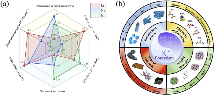
 DownLoad:
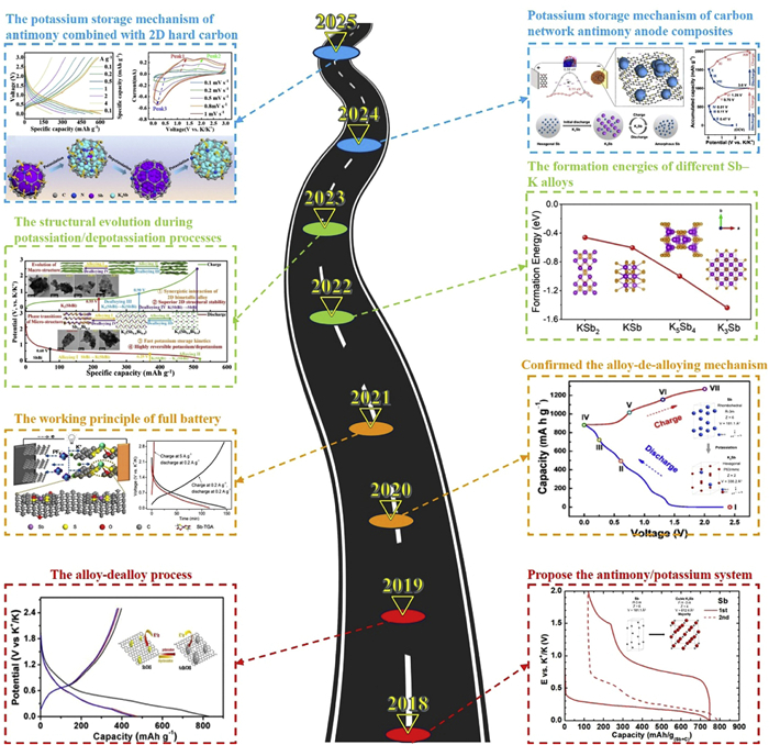
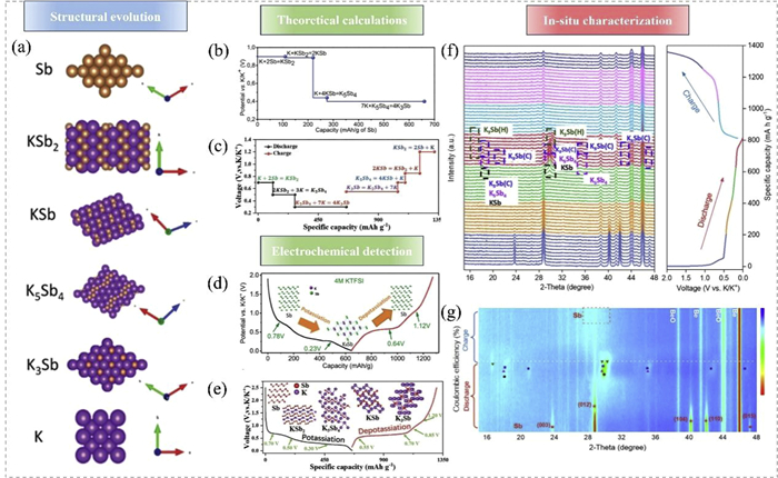
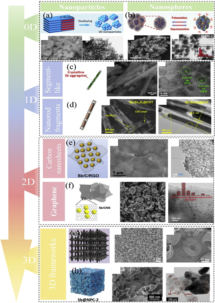
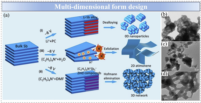
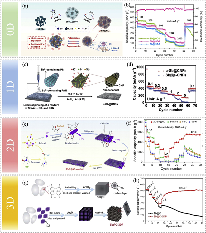
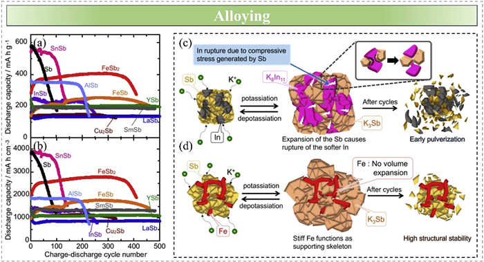
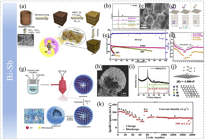
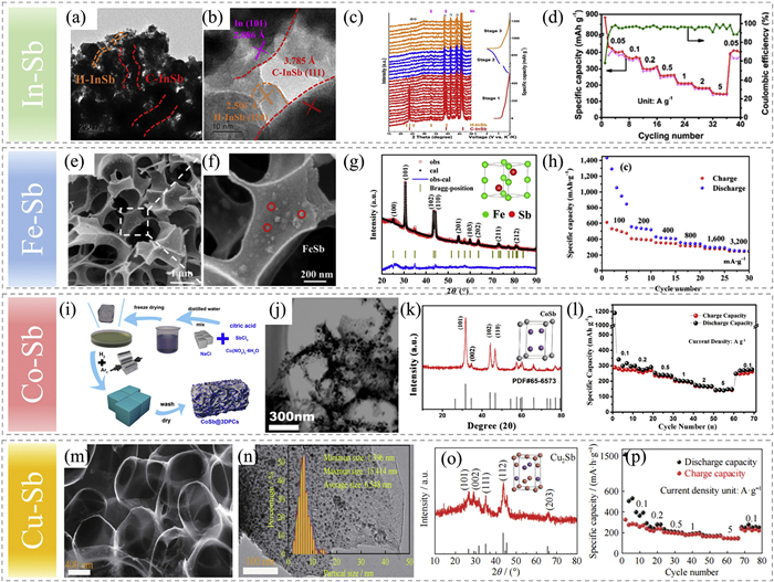
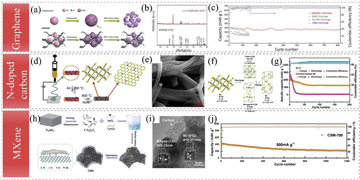
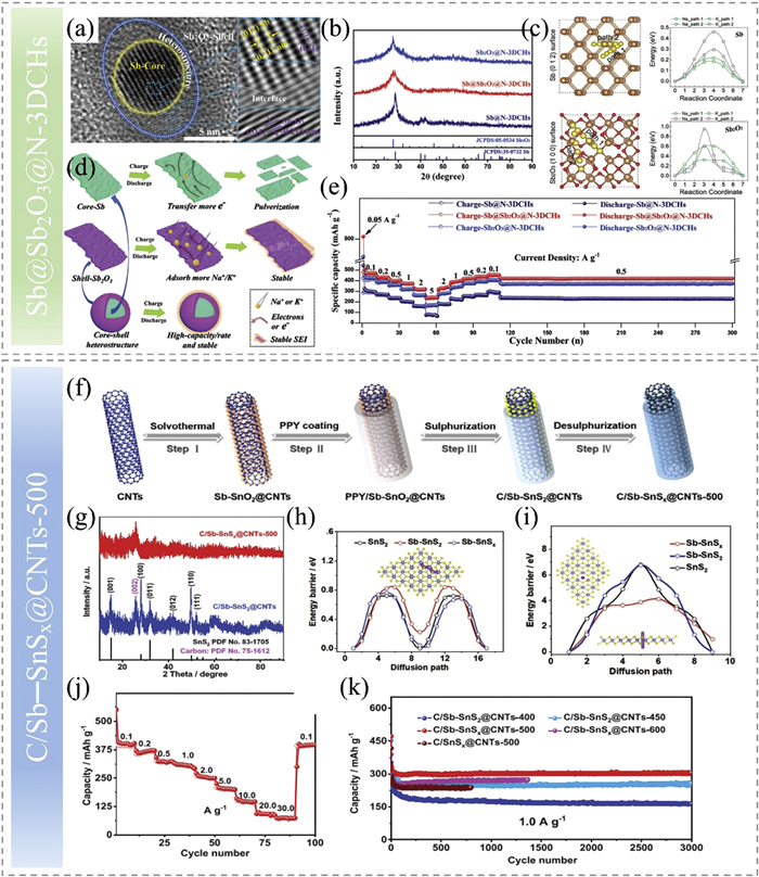
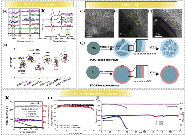
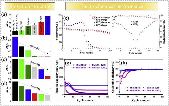
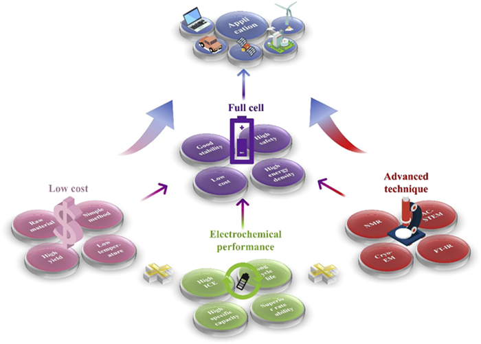

 下载:
下载:


 下载:
下载:

