Figure 1.
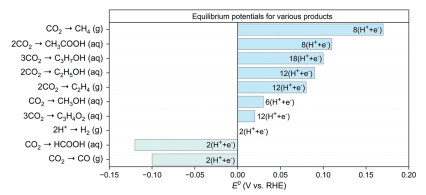
CO2RR-to-products and corresponding thermodynamic equilibrium potentials. Reproduced with permission [49]. Copyright 2022, Wiley-VCH GmbH.
Bismuth-based architectures engineering for selective CO2 electroreduction to formate
Xiaoli Zhao , Lijuan Yang , Yong Hao , Yi Cheng , Fei Li , Xinghua Zhu , Ming Huang

The relentless consumption of fossil fuels has escalated atmospheric CO2 concentrations, exacerbating climate crises ranging from intensified heatwaves to ecological imbalances [1-6]. This environmental emergency coincides with a looming energy security threat as conventional hydrocarbon reserves dwindle, demanding urgent development of technologies that reconcile carbon mitigation with sustainable energy storage. The conversion of CO2 has emerged as a promising solution, capable of converting CO2 into value-added chemicals [7-10]. However, the CO2 inherent stability as its strong C=O bonds [11,12], poses formidable activation challenges, necessitating substantial energy input to overcome the reaction barriers. Electrocatalytic CO2 reduction (CO2RR) has emerged as the preeminent pathway for CO2 valorization [13-21], demonstrating compelling advantages over thermochemical and photochemical alternatives [22-28]. Unlike energy-intensive thermochemical processes or photon-efficiency-limited photocatalytic systems, CO2RR operates under mild conditions while achieving high product selectivity and tunable energy input. A key technological advantage is its inherent compatibility with membrane electrode assembly (MEA) configurations, enabling direct integration with intermittent renewable electricity sources for enhanced system efficiency and carbon utilization. Critically, recent breakthroughs in solid electrolyte engineering have facilitated sustained operation at industrially relevant current densities (e.g., > 200 mA/cm2), positioning electrocatalysis as a uniquely viable technology currently meeting the critical technical and economic feasibility thresholds for scalable CO2 conversion.
Among CO2RR products, formate stands out as the optimal target due to its unique combination of thermodynamic accessibility and industrial relevance. Its direct 2-electron reduction pathway bypasses kinetic limitations inherent to multi-electron processes, effectively suppressing competing hydrogen evolution reaction (HER) and requiring minimal overpotentials [29-32]. Beyond these fundamental advantages, formate serves as a versatile platform chemical with expanding commercial utility in hydrogen storage platforms, pharmaceutical precursors, and sustainable fertilizers [33-35]. For realizing this formate-centric pathway, bismuth-based catalysts represent the leading electrocatalytic solution, distinguished by near-exclusive selectivity, environmental compatibility, and cost-effectiveness [36-38]. These merits collectively position Bi materials as prime candidates for industrial deployment. While recent breakthroughs have achieved industrial current densities (> 200 mA/cm2) with > 95% Faradaic efficiency for formate, critical challenges persist in operational stability, energy efficiency, and carbon utilization at low overpotentials—metrics essential for commercial deployment. Overcoming these barriers necessitates deliberate catalyst engineering strategies encompassing morphology control (e.g., nanoflowers [39,40], nanorods [41,42], nanosheets [43,44]) and electronic structure modulation. Recent operando investigations reveal that dynamic reconstruction forms stabilized Bi-O-C interfacial structures, imparting exceptional operational durability. Advances in this domain have yielded bismuth catalysts (Bi0.6Cu0.4 NSs) demonstrating stable operation exceeding 260 mA/cm2 for 400 h—significantly surpassing conventional metal catalysts (e.g., Sn, Cu)—in both activity and stability metrics [45]. Accelerating these high-performance Bi electrocatalyst systems is pivotal for advancing scalable CO2 conversion technologies that address energy sustainability and climate mitigation, furthering low-carbon circularity imperatives.
Recent reviews have advanced understanding of Bi-based catalysts through material classification [46], mechanistic operando studies [47], and multi-metal comparisons [48]. However, these works insufficiently bridge atomic-scale catalyst design, dynamic interfacial behavior, and industrial system integration for sustainable CO2RR-to-formate conversion. Here, we provide a focused and comprehensive analysis of Bi-specific architectures—spanning metallic bismuth nanostructures, atomically dispersed configurations, engineered compounds, interfacial heterostructures, and rationally designed alloys. Integrating operando characterization techniques with computational modeling, we elucidate how atomic-scale motifs dictate reaction intermediate stabilization and selectivity pathways. Importantly, it also examines dynamic catalyst reconstruction during operation, resolving unprecedented insights into their true active states and stability. Systematic analysis of synthesis-modulation effects establishes design principles linking multi-scale features (morphology, coordination, doping) to activity-stability tradeoffs. By integrating experimental insights with theoretical modeling, this review proposes a design framework to advance next-generation electrocatalysts, offering methodological guidance for sustainable carbon-neutral technologies.
The rational design of efficient electrocatalysts for CO2RR requires a comprehensive understanding of both thermodynamic limitations and kinetic barriers inherent to this complex process. A critical obstacle arises from the thermodynamic proximity between CO2 reduction potentials and HER (Fig. 1) [49,50]. The equilibrium potential for formate production is positioned merely 120 mV above HER. This narrow potential window inherently complicates selectivity control, exacerbated by the high stability of CO2 molecules (C=O bond energy: 750 kJ/mol), which imposes substantial activation barriers necessitating overpotentials [51]. The reaction pathway diversity further intensifies these challenges: 2-Electron transfer produces formate via *OCHO intermediate stabilization [52,53], while 6- to 18-electron processes yield methanol [54], CO [55], and C2+ products such as ethylene [56] and ethanol [57]. Thermodynamic analysis alone remains insufficient for predicting practical outcomes, as kinetic factors, particularly the adsorption energetics of intermediates like *COOH and *OCHO, govern pathway bifurcations. The linear geometry of CO2 and high C=O bond cleavage energy demand catalysts that stabilize transition states while suppressing HER through precise proton-electron transfer modulation.
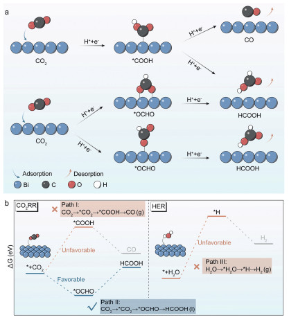
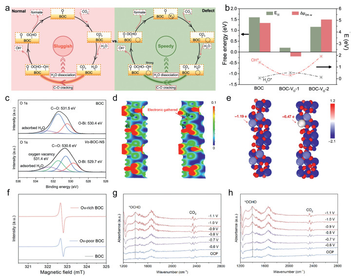
The electrocatalytic reduction of CO2 to formate proceeds through a proton-coupled two-electron transfer mechanism initiated by CO2 adsorption at catalytic active sites. The electrocatalytic pathway involves four concerted steps: CO2 adsorption on active sites, electron transfer to form *CO2- radical anions, proton-coupled hydrogenation to *OCHO intermediates and product desorption [58]. Upon electron injection, the adsorbed CO2 forms a bent *CO2- radical anion, whose subsequent protonation pathway is governed by the surface adsorption strength (Fig. 2a). Strong *CO2- binding favors oxygen-bound protonation, generating *COOH intermediates that desorb as CO, while weak adsorption promotes carbon-bound protonation to form *OCHO intermediates and achieve the direct precursor for formate production [51]. This selectivity-determining step arises from the catalyst's ability to modulate charge distribution at the *CO2- interface, where Bi-based materials exhibit unique electronic stabilization of *OCHO through p-orbital hybridization (Fig. 2b). The Bi 6p orbitals engage in directional electron donation with the oxygen atoms of *OCHO, lowering the intermediate's formation energy compared to *COOH pathways. Concurrently, the weak hydrogen adsorption energy of Bi intrinsically elevates HER overpotentials, kinetically suppressing competitive proton reduction. The reaction concludes with formate desorption, facilitated by the moderate binding strength of *OCHO to Bi surfaces, which balances intermediate stabilization and product release. Recent studies reveal divergent active phases for Bi-based catalysts—metallic Bi vs. hydroxylated Bi2O2CO3—depending on electrochemical conditions. Metallic Bi dominates under moderate cathodic potentials (e.g., −0.8 to −1.0 V vs. RHE), where its p-orbital hybridization stabilizes *OCHO intermediates [59]. Conversely, in near-neutral electrolytes or lower potentials (< −0.7 V), in situ formation of hydroxyl‑rich Bi2O2CO3 enhances water dissociation, facilitating *OCHO hydrogenation [60]. This duality underscores the importance of operando characterization to resolve active sites under working conditions.
As a group VA element with a distinctive covalent bonding configuration and natural abundance in compound forms, Bi has emerged as a cost-effective, eco-friendly, and high-performance candidate for electrocatalytic CO2RR. Its intrinsic merits, including moderate *CO2 adsorption energy, selective suppression of HER, and unique p-orbital electronic structure, position Bi-based materials as ideal catalysts for formic acid generation [61]. Recent studies demonstrate Bi-based catalysts deliver high Faradaic efficiency (FE) for formate in aqueous electrolytes with exceptional stability over broad potential ranges, stimulating significant research interest [36,62]. Subsequent advances in bismuth-based electrocatalysis have converged on three synergistic design principles: material diversification (atomic-scale configurations to alloy systems), nanostructural engineering (electrochemically reconstructed architectures), and mechanistic interrogation (operando spectroscopic tracking of *OCHO intermediates). Collectively, these strategies achieve > 90% formate selectivity at industrially relevant current densities while correlating the electronic states with product distribution.
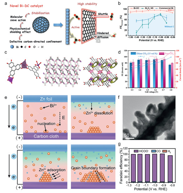
The exploration of Bi-based catalysts for electrocatalytic CO2 reduction to formic acid/formate has evolved significantly since foundational efforts by Komatsu and collaborators [36]. Early studies focused on synthesizing Bi nanomaterials with diverse morphologies, including nanoparticles [63-66], nanotubes [29,67], nanoflowers [68,69], nanodendrites [70,71] and nanosheets [72-75]. These nanostructures introduce catalytically active defects such as edges, steps and corners [76], which synergistically enhance CO2 adsorption and reduce energy barriers for stabilizing the *OCHO intermediate, thereby optimizing formate production efficiency. For instance, thermal decomposition under inert atmospheres yields defect-rich Bi nanoparticles (Bi-DC, Fig. 3a) with carbon modified interfaces [77]. The formate Faradaic efficiency (FEformate) was as high as 95.7% at −1.06 V vs. RHE (Fig. 3b). It also exhibited robust CO2 adsorption and hydrophobicity, ensuring stable operation for 120 h at 0.4 A/cm2 in membrane electrode assemblies. The rod-shaped Bi-based metal organic frameworks (Bi-HHTP) were produced by solvothermal synthesis (Fig. 3c). Its microporous framework incorporates unidirectional channels (16% porosity) with Bi3+ions adopting distorted tetrahedral and square-pyramidal coordination geometries. This material has been able to achieve high purity formic acid production at dilute CO2 concentrations (Fig. 3d) [78]. In addition, the synthesis of Bi nanodendritic crystals can also be rapidly achieved using a galvanic-cell deposition method at room temperature (Figs. 3e and f), in which the exposed low-angle grain boundaries significantly improve the electronic structure of the catalysts. Product analysis confirms > 92.0% FEformate across broad potentials in flow cells, peaking at 96.7% (Fig. 3g) [79].
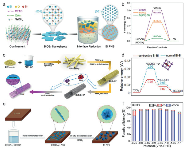
Indirect conversion strategies, particularly in situ electrochemical reconstruction, offer versatile pathways for synthesizing high-performance Bi catalysts. For instance, chemical interface constrained reduction of BiOBr nanosheets produces porous Bi nanosheets (Fig. 4a) [80], doubling the electrochemical active surface area compared to conventional Bi powders, while significantly lowering the energy barrier for HCOO* intermediate formation (Fig. 4b), achieving a FEformate of 95.2%. Similarly, hollow fiber Bi catalysts were fabricated via reverse spinning/sintering and electroreduction (Fig. 4c), feature a stable framework with contracted Bi-Bi bonds [81]. The Bi (012) facet exhibits ΔG values of 0.09 and 0.05 eV for *OCHO intermediate formation with ideal and contracted Bi-Bi bonds, respectively (Fig. 4d). This reduced activation barrier confirms that contracted Bi-Bi bonding facilitates the CO2RR-to-formate on Bi HF electrode. Another approach involves reconstructing Bi@Bi2O3 nanodendrites into Bi nanoflowers (Bi-NFs) through chemical/electrochemical reduction (Fig. 4e) [82]. The Bi-NFs catalyst achieves a peak FEformate of 92.3% at −0.9 V vs. RHE while maintaining > 90% efficiency across −0.8 to −1.0 V (Fig. 4f). This high selectivity is attributed to in situ reconstruction-derived Bi@Bi2O3-NDs, which generate abundant catalytically active Bi0 centers.
Optimizing electrical conductivity and active site architecture in metallic Bi electrocatalysts represents a critical research frontier. Future investigations should prioritize crystallographic engineering of bismuth nanostructures to regulate charge transfer kinetics and intermediate adsorption configurations, particularly through facet-controlled synthesis and lattice strain modulation. Hierarchical porosity engineering and in situ reconstruction protocols are essential design strategies for achieving industrial current densities while maintaining high formate selectivity. Concurrently, atomic-resolution in situ techniques—including synchrotron-based X-ray diffraction and electrochemical scanning tunneling microscopy—should elucidate potential-dependent reconstruction mechanisms of metallic Bi under operating conditions. These fundamental investigations into structure-property correlations will establish design principles for next-generation Bi catalysts at industrial current densities.
Single-atom catalysts (SACs), characterized by isolated metal atoms anchored on support matrices [83-85], have emerged as a frontier in electrocatalytic CO2 reduction since the initial validation in 2011 [86]. The unique configuration of SACs maximizes atomic utilization efficiency while creating well-defined active sites, offering exceptional opportunities for tailoring reaction pathways [87]. Bi SACs exhibit tunable product selectivity for CO2 reduction—directed toward formate or CO—depending on their coordination environment [88,89]. Strategic engineering of carbon-coordinated and oxide-supported Bi sites could stabilize *OCHO intermediates for formate production.
Notable advances include the integration of Bi single atoms into SnO2 matrices to generate oxygen vacancies (Fig. 5a) [90], which effectively stabilize HCOO* intermediates and sustain high FEformate under industrial-level current densities of 300 mA/cm2 (Fig. 5b). Parallel enhancements emerge in Bi intercalated BiOBr nanosheets (Bi/BiOBr-D) [91], where atomic Bi incorporation strengthens HCOO* interaction (Fig. 5c) through optimized p-band center alignment and enhanced orbital coupling (Fig. 5d). This electronic synergy yields exceptional current density (jHCOOH = 815 mA/cm2) and productivity (15.22 mmol h−1 cm−2), surpassing conventional bismuth-based electrocatalysts. Moreover, complementary mechanistic understanding emerges from in situ X-ray absorption spectroscopy (XAS) studies of Bi atoms adsorbed on Pd nanoparticles [92]. These reveal oxygen-containing species adsorption on Bi sites and direct participation in CO2RR through HC(O*-Bi)2 intermediate formation via Bi-O coordination (Figs. 5e and f). This unique interaction reduces the intermediate energy barrier, enabling a threefold increase in local formate concentration (1.6 mmol/L to 4.6 mmol/L) at −0.15 V vs. RHE (Fig. 5g). Atomic-scale evidence confirming bismuth functions as both catalytic center and electronic modifier resolves persistent controversies regarding bismuth catalytic mechanisms, thereby establishing theoretical foundations for rational design of Bi SACs.
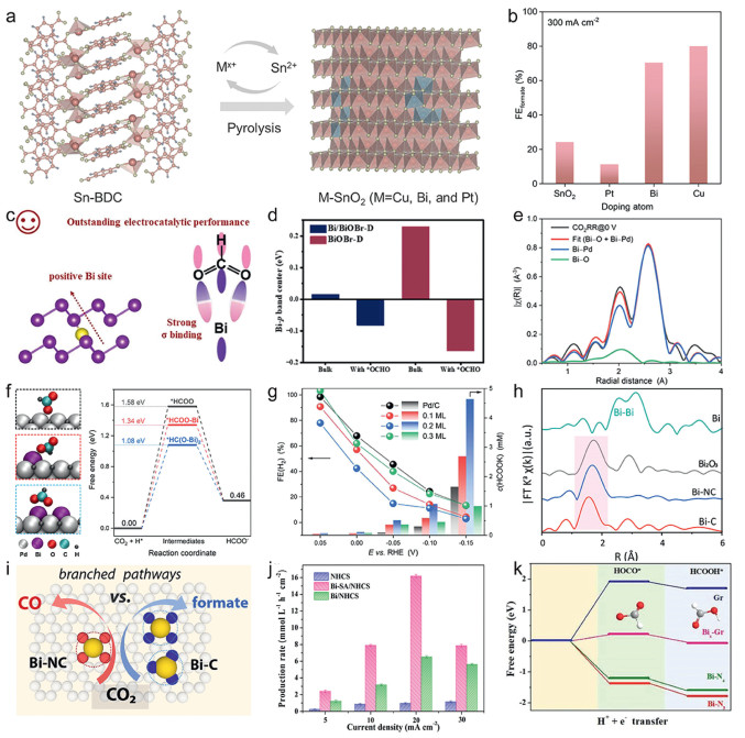
Recent structural insights into graphene-supported Bi SACs reveal critical structure-selectivity relationships. Advanced characterization of Bi SACs anchored on graphene derivatives [93] confirms atomic dispersion via absent Bi-Bi metallic bonds and characteristic Bi-C/N coordination (Fig. 5h). Crucially, product selectivity is governed by the local coordination chemistry, in which C-coordinated Bi sites preferentially drive formate generation (FEformate > 90%), while N-coordinated counterparts favor CO production, demonstrating ligand-dependent catalytic switching (Fig. 5i). Another paradigm involves embedding Bi atoms within nitrogen doped carbon frameworks [94], which achieved sustained near-unity Faradaic efficiency with a formate production rate of 16.2 mmol L−1 h−1 cm−2 (Fig. 5j). Theoretical analysis reveals that the Bi-N3 coordination modulates reaction thermodynamics by converting the rate-determining step from endothermic to exothermic, substantially reducing activation barriers for HCOO* and subsequent protonation to HCOOH (Fig. 5k).
Despite these achievements, challenges persist in the rational design of Bi SACs. Key design principles include stabilizing Bi–N/C coordination to lower energy barriers and optimizing charge transfer matrices to accelerate *OCHO intermediate formation. Key knowledge gaps include the exact nature of active sites under operational conditions, dynamic evolution of intermediates, and the interplay between support defects and catalytic performance. Moreover, the relative infancy of SACs technology necessitates further exploration into scalable synthesis methods and long-term stability assessment.
Pure Bi encounters inherent limitations in direct electrocatalytic applications owing to oxidative degradation and structural instability under operational conditions, motivating substantial research focus on engineered bismuth-based compounds. These derivatives overcome constraints of metallic bismuth through enhanced electrochemical durability and improved CO2 activation kinetics, demonstrating exceptional formate production selectivity. Structural adaptability across bismuth compounds enables precise tuning of coordination environments and charge distribution. Representative systems including Bi2X3 (X=O, S, Se), Bi2O2CO3, and BiOX (X = Cl, Br, I) demonstrate particular efficacy, establishing Bi-based materials as versatile platforms for high-efficiency CO2-to-formate conversion.
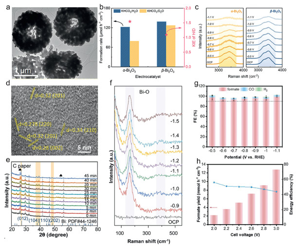
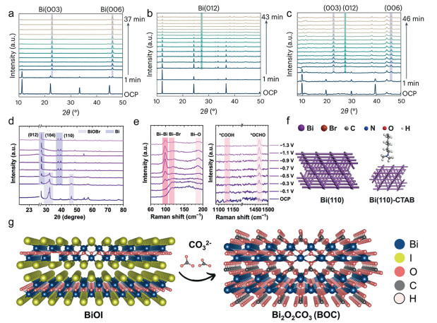
As a pivotal component in Bi-based electrocatalysts for CO2 reduction, Bi-based oxides and chalcogenides (Bi2X3; X=O, S, Se) have garnered substantial attention due to its tunable structural and electronic properties. Strategic structural engineering enables precise optimization of active site distribution, charge transfer dynamics, and intermediate stabilization to enhance the formate production efficiency [95]. For example, the structural superiority of β-Bi2O3 in CO2RR emerges through comparative studies with α-phase counterparts. The enhanced water activation capability of coral-like β-Bi2O3 over α-Bi2O3, evidenced by reduced kinetic isotope effect and intensified -OH vibrational peaks (Figs. 6a–c) [96], accelerates protonation kinetics through efficient *OCHO intermediate formation. Complementary structural analyses via in situ XRD/Raman (Figs. 6d–f) reveal that grain boundary-rich architectures effectively stabilize Bi3+ species, maintaining optimal Bi3+/Bi0 interfaces for sustained catalysis. These structural advantages contribute to exceptional FEformate (> 90%) for β-Bi2O3 across a broad potential window (−0.5 to −1.1 V vs. RHE) (Fig. 6g). Practical implementation in MEA cells achieves a formate production rate of 12.72 mmol h−1 cm−2 at 3.2 V cell voltage (Fig. 6h) [97].
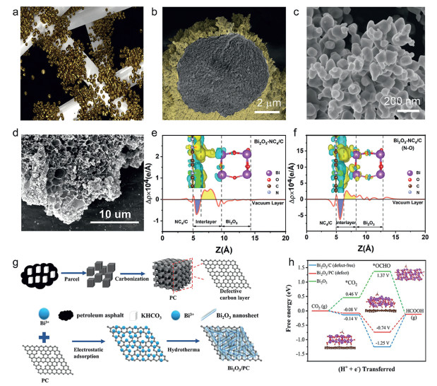
The integration of Bi2O3 with carbon matrices represents a particularly promising approach, leveraging the synergistic effects between metallic oxides and conductive substrates [98-101]. Three-dimensional fractal Bi2O3 architectures grown on carbon fiber paper exemplify this strategy (Fig. 7a) [102], where the hierarchical porosity and edge-enriched β-phase Bi2O3 create abundant catalytically active interfaces (Figs. 7b and c). Such configurations enhance CO2 adsorption capacity while facilitating efficient electron transport through the conductive carbon framework, demonstrating the dual benefits of morphological control and substrate engineering. Advanced synthesis techniques further expand the design space for Bi2O3-carbon composites. Laser irradiation of hydrothermally derived Bi2O3 on porous carbon substrates creates Bi2O3@LPC hybrids [103], where the interconnected porous network ensures uniform dispersion of Bi2O3 nanoparticles (Fig. 7d). Critical to this configuration is the formation of N-O-Bi interfacial bonds through laser-induced nitrogen incorporation, which substantially enhances interfacial charge transfer kinetics (Figs. 7e and f). The synergy between optimized Bi2O3 distribution and accelerated electron transport enables the Bi2O3@LPC system to achieve FEformate of 96%. Similarly, another strategy involves in situ growth of Bi2O3 nanosheets on defect-engineered porous carbon (Bi2O3/PC, Fig. 7g) [104]. Oxygen-mediated electron transfer from carbon defects to Bi active sites promotes electron accumulation at catalytic centers, effectively reducing the energy barrier for *OCHO intermediate stabilization. Simultaneously, the three-dimensional Bi2O3 network architecture enhances CO2 adsorption capacity while minimizing electron transfer resistance through continuous conductive pathways (Fig. 7h). This dual optimization of electronic structure and mass transport properties culminates in exceptional catalytic performance, attaining FEformate of 99% at 150 mA/cm2.
Elemental doping has emerged as a critical strategy for engineering the electronic properties of Bi2O3-based electrocatalysts, drawing inspiration from semiconductor technology to enhance charge transport and catalytic activity [105]. This approach capitalizes on hydrothermal and solvothermal synthesis methods, which have become foundational techniques for creating doped Bi2O3 architectures due to their versatility in controlling material composition and morphology. A representative example involves vanadium-doped Bi2O3 synthesized through a one-step hydrothermal process [106], where V incorporation induces lattice amorphization while reducing electron density at Bi sites. This electronic configuration strengthens CO2 adsorption through enhanced orbital interactions, achieving FEformate of 94.2%. Parallel advancements in sulfur doping demonstrate complementary benefits. Solvothermally prepared S-doped Bi2O3-carbon nanotube hybrids (S-Bi2O3-CNT) exhibit modified electronic structures [107], evidenced by absorption edge shifts. DFT analyses reveal that sulfur doping restricts electron transfer from Bi to adjacent S/O atoms, creating delocalized electron clouds around Bi centers. This electron redistribution facilitates *CO2 intermediate stabilization and enables spontaneous *HCOO migration between neighboring Bi sites, synergistically achieving FEformate of 97.1%. Subsequent electrochemical analyses confirm enhanced catalytic kinetics in S-doped systems, manifested through negative-shifted reduction potentials and elevated current densities [108]. The modified surface chemistry promotes hydroxide adsorption, accelerating *H formation for subsequent CO2 hydrogenation to *HCOO intermediates. These findings collectively establish elemental doping as a multifaceted tool for simultaneously optimizing electronic structure, surface reactivity, and reaction pathways in CO2 reduction systems.
Bi2S3 catalysts demonstrate exceptional CO2RR performance through in situ reconstruction and defect engineering. Wang et al. revealed that Bi2S3 nanofiber bunches outperform nanoflowers due to larger surface area and faster charge transfer, achieving 96% FE at −0.75 V vs. RHE [109]. Ma et al. further demonstrated that electrochemically reduced Bi2S3 forms S-doped Bi nanoplates, where residual S (0.3–0.7 wt%) stabilizes the OCHO* intermediate via enhanced p-band upshifting, lowering the free-energy barrier for formate production (FE > 93%) [110]. Advanced in situ characterization confirms that Bi2S3 undergoes topotactic transformation into Bi/Bi2O2CO3 nanocomposites under operational potentials. Metallic Bi nanoparticles serve as active sites, while oxygen vacancies promote CO2 chemisorption and proton-rich surfaces accelerate *OCHO formation [111]. Defect-rich 2D Bi2S3 nanosheets leverage S dopants to facilitate H2O dissociation, concentrating K+ ions near active sites. This dual effect stabilizes reaction intermediates, yielding a FEformate above 90% over a wide potential window and a high stability over 200 h [112]. Jiang et al. designed S-doped Bi catalysts via Bi2S3 reconstruction, achieving > 95% FE at 2000 mA/cm2 in pH-universal electrolytes, with S optimizing p-orbital delocalization for OCHO* stabilization [113]. For Bi2Se3, Cu doping generates Se vacancies that enhance CO2 adsorption and modulate electronic structures. The resultant Cu-Bi2Se3 catalyst achieves 65.31% FE at low overpotentials (−500 mV), highlighting the role of heteroatom integration in tuning intermediate stabilization [114]. Collectively, Bi2S3 and Bi2Se3 systems leverage structural reconstruction, defect engineering, and electronic modulation to rival or even surpass Bi2O3 in formate selectivity and operational stability.
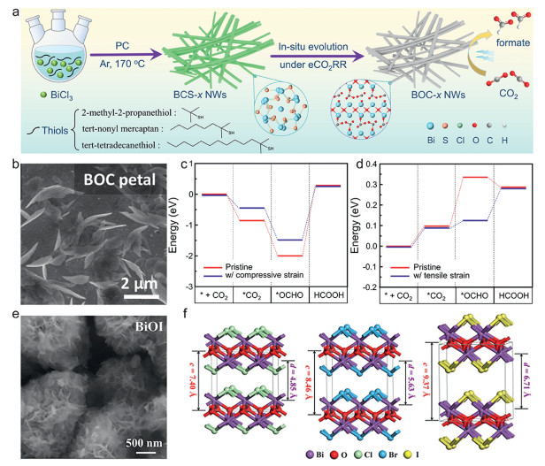
Bismuth oxycarbonate (Bi2O2CO3, BOC) has emerged as a model system owing to its structural abundance of Bi-O bonds and the isotopic traceability of carbonate moieties, rendering it particularly suitable for mechanistic investigations in CO2RR. Morphological control significantly enhances BOC performance, as demonstrated by ultrathin Bi4Cl2S5 nanowire-derived BOC, which achieves 92.9% FEformate at 500 mV overpotential through high active surface area and enhanced charge transport via 1D structuring (Fig. 8a) [115]. The petal-like BOC catalysts were synthesized via spontaneous reactions between Bi films and carbonate solutions [116]. During electrochemical activation, partial reduction generates a hybrid R-BOC phase containing both Bi2O2CO3 and metallic Bi (Fig. 8b). The hierarchical architecture exposes multiple catalytically active facets (edges, terraces) while maintaining structural integrity. DFT calculations reveal that the superior performance originates from metallic Bi domains, which stabilize the *OCHO intermediate, reducing reaction energy barriers compared to pristine BOC (Figs. 8c and d). This electronic optimization enables R-BOC to achieve an exceptional FEformate of 95.9%. Similarly, the ion-exchange synthesis of Bi2O2CO3 from BiOI preserves expanded interlayer spacing (Figs. 8e and f) and weakened [Bi2O2]2+/I− interactions in nanosheet-assembled microspheres [117]. This hierarchical architecture enhances bicarbonate ion diffusion while stabilizing Bi-O configurations during CO2RR, achieving FEformate of 98%. Such structural inheritance demonstrates the critical role of interlayer engineering in optimizing ion transport and catalyst durability.
The oxygen vacancy-enriched BOC materials were synthesized through defect chemistry strategies [118], providing direct spectroscopic evidence for CO2 chemisorption at vacancy sites with subsequent carbonate formation (Fig. 9a). Their operando analyses further revealed that these oxygen vacancies serve dual functions. The activated H-OH bond cleavage generates adsorbed hydroxyl species while optimized electronic interactions stabilize key reaction intermediates (Fig. 9b). This vacancy-mediated synergy achieves a FEformate of 94%. Similarly, oxygen vacancy engineering during reconstruction induces localized electron accumulation at Bi sites (Figs. 9c–e), creating an electronic microenvironment that strengthens *OCHO adsorption [119]. Elevated oxygen vacancy concentration in BOC enhances CO2/*OCHO adsorption, accelerating formate formation to achieve exceptional FEformate of 97.5% and durability for 100 h (Figs. 9f–h) [120]. This highlights the potential of vacancy engineering in promoting CO2RR kinetics through optimized intermediate stabilization.
Heteroatom doping methodologies substantially enhance the catalytic capabilities of BOC, exemplified by Cu-modified BOC nanosheets that self-assemble into hierarchically porous floral nanostructures via hydrothermal synthesis [121]. DFT calculation confirms that Cu incorporation induces electron redistribution around Bi centers, lowering the Gibbs free energy barrier for the rate-determining step from *OCHO to formate. The combined effects of optimized electronic structure and hierarchical porosity empower Cu-BOC with a record FEformate of 98.5%. In situ spectroscopic analyses confirm that Cu doping elevates Bi-site electron density in BOC, while intensifying the orbital hybridization between Bi 6p and O 2p in *OCHO intermediates [122]. This electronic modulation mechanism extends to Ce-doped [123] and S-doped [124] BOC systems, demonstrating doping enhancement of CO2RR performance. Multi-element doping studies confirm the universality of this approach while elucidating fundamental structure-activity relationships through systematic comparisons of charge redistribution patterns and intermediate stabilization energies. The conserved enhancement mechanism across heteroatom-doped BOC catalysts, involving optimized charge transfer and strengthened orbital interactions, establishes a theoretical basis for electronic structure engineering. These collective findings establish a foundational framework for rational dopant selection and electronic structure engineering in advanced catalyst design.
BiOX systems (X = Cl, Br, I) derived from chlorine/bromine/iodine provide tunable platforms for mechanistic studies of CO2 electroreduction and high-efficiency formate synthesis. In situ XRD analyses reveal distinct facet-selective reconstruction behaviors during CO2RR, where Br- induces preferential exposure of the Bi (003) facet (Fig. 10a), Cl- facilitates formation of the stepped Bi (012) facet (Fig. 10b), and I- results in mixed facet orientations (Fig. 10c) [125]. Comparative performance evaluation demonstrates superior formate selectivity of BiOBr over BiOCl and BiOI counterparts, directly correlating the enhanced intrinsic activity of Bi (003) facet. These findings establish a crystallographic foundation for understanding halogen-dependent active site evolution in CO2RR catalysis. Electrochemical reconstruction strategies further amplify BiOX catalytic capabilities. CTAB-functionalized BiOBr (CT/h-BiOBr) nanoflower undergoes dynamic structural reorganization to expose the Bi (110) facet under operational conditions (Figs. 10d and f) [126]. Synergistic effects between the surfactant's hydrophobic chains and the reconstructed facet create a CO2-enriched interfacial microenvironment (Fig. 10e). This dual engineering enables sustained FEformate over 90% across a broad potential window (−0.6 to −1.2 V vs. RHE), demonstrating exceptional potential adaptability. Similarly, gas diffusion electrode (GDE)-supported BiOI undergoes complete phase transformation into crystalline Bi2O2CO3 during cathodic activation (Fig. 10g) [127]. The resultant ordered architecture combines high structural integrity with efficient mass transport, achieving FEformate of 90% retention over 30 h at industrial current densities (100–300 mA/cm2), thereby addressing critical scalability challenges in CO2 electrolyzer design.
Strategic design of bismuth functional oxides, sulfides, and oxysalts requires concerted optimization of crystalline phases, charge transport pathways, and electron density redistribution. Precise phase engineering, targeted heteroatom doping, and oxygen vacancy engineering create tailored coordination environments that reduce *OCHO formation barriers and stabilize its adsorption, thus promoting formate production. Future development must resolve operando phase transitions and atomically regulate dopant distributions using cryo-electron microscopy and X-ray absorption fine structure spectroscopy. These advances will establish functional bismuth compounds achieving > 90% formate selectivity at 200 mA/cm2 with 200-h stability.
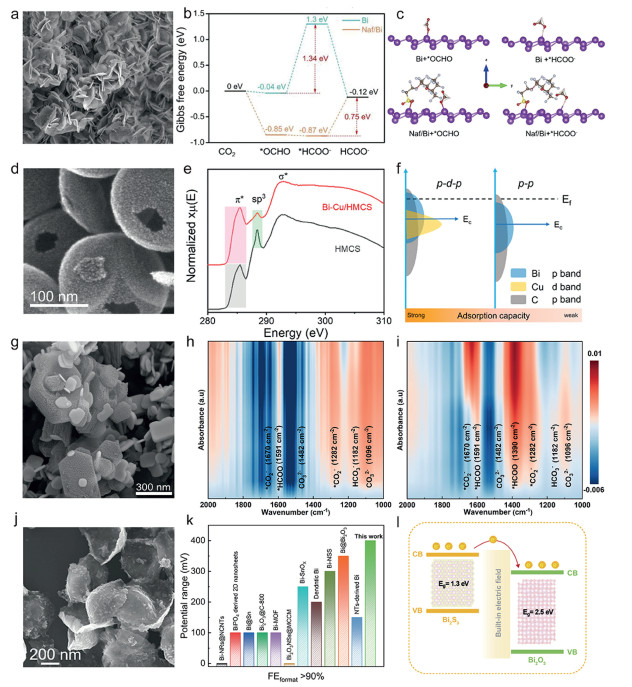
The rational design of heterojunctions through tailored interfacial interactions has become a pivotal strategy for optimizing bismuth-based electrocatalysts in CO2 reduction. By coupling Bi with materials of complementary electronic properties, these heterostructures achieve synergistic enhancements in charge transfer kinetics, intermediate stabilization, and catalytic durability [128-131]. A representative example is the Nafion/Bi catalyst synthesized on a Cu framework, which forms a hierarchical flower-like architecture (Fig. 11a) [132]. This structure not only maximizes CO2-accessible surface area but also establishes an electronic interface between Nafion and Bi. The interfacial interaction shifts the rate-limiting step from the second hydrogenation to the desorption process of HCOOH (Fig. 11b), while Nafion concurrently stabilizes the HCOO* intermediate (Fig. 11c), collectively accelerating the CO2 reduction pathway. Similarly, the Bi-Cu/HMCS heterojunction, featuring nanobubble-like morphology (Fig. 11d), enhances π*-orbital interactions between Cu and carbon matrices (Fig. 11e) [133]. This configuration promotes efficient adsorption of both *HCOO and *CO intermediates (Fig. 11f), achieving FEformate of nearly 100% at −0.7 V vs. RHE. The hierarchical integration of porous graphene (PG) with BiOCl1-x nanosheets leverages high surface area of PG to anchor BiOCl (Fig. 11g) [134], enhancing CO2 adsorption at Bi sites while preventing aggregation of nanosheets. Synergistic Cl vacancy and PG interactions further stabilize HCOO* intermediates via enhanced charge redistribution (Figs. 11h and i). These synergistic structural-electronic effects enable durable FEformate (> 85%) over 100 h operation. The Bi2O3-Bi2S3 heterojunction further exemplifies this strategy (Fig. 11j), sustaining FEformate over 90% at 400 mV overpotential (Fig. 11k) [135]. Its rough surface morphology enhances CO2 adsorption, while the interfacial electron transfer from Bi2S3 to Bi2O3 optimizes charge delivery to reaction intermediates (Fig. 11l).
Beyond static configurations, electrochemically reconstructed heterojunctions enable dynamic interfacial self-adaptation during operation. For instance, Bi-TA precursors undergo HCO3−-mediated ion exchange to form Bi2O2CO3, which was subsequently reduced to metallic Bi under cathodic potential. Spontaneous coupling between Bi and residual Bi2O2CO3 yields Bi/Bi2O2CO3 heterojunctions enriched with Biδ⁺ active sites. These interfaces significantly strengthen *OCHO intermediate adsorption via optimized orbital interactions, thereby achieving a formic acid energy conversion efficiency exceeding 50% at a current density of 250 mA/cm2 [136]. Comparative post-reduction characterization of Bi2O3 [137] and Bi2S3 [138] systems further demonstrates that alkaline electrolytes and CO2 atmosphere are prerequisites for stabilizing surface Bi2O2CO3 phases, thus preserving heterostructures like Bi2O2CO3/Bi2O3 or Bi2O2CO3/Bi under operational potentials. Crucially, interfacial electron redistribution alters p-orbital occupancy of Bi atoms, lowering the energy barrier for *OCHO formation and accelerating formate generation kinetics. This dynamic self-optimization mechanism ultimately achieves FEformate of 93% at an industrial-scale current density of 2 A/cm2.
While Bi-based heterojunctions demonstrate enhanced CO2RR performance through interfacial charge redistribution, lattice mismatch-induced defects, and protective component integration, critical challenges persist in understanding their dynamic interface evolution under operational conditions. The multifunctional nature of these catalysts arises from synergistic mechanisms: (i) Complementary active site provision by constituent phases; (ii) optimized *OCHO adsorption via interfacial electron redistribution; (iii) defect generation (oxygen vacancies, grain boundaries) through lattice mismatch; and (iv) protective layers preventing component corrosion. However, in situ reduction dynamically alter interfacial defect distributions and electronic states, leading to unpredictable performance decay during prolonged operation. To address these limitations, future designs must prioritize atomically controllable fabrication methods and advanced operando characterization. Universal design principles include creating charge-redistributed interfaces to strengthen *OCHO adsorption and leveraging lattice mismatch to generate defect-rich active sites, collectively reducing overpotentials.
Bimetallic alloys consistently demonstrate superior catalytic performance over monometallic systems in CO2RR, as evidenced by numerous studies [139,140]. This enhancement originates from alloying-induced electronic structure modulation, which enables precise control over intermediate adsorption/desorption energetics [141,142]. Bismuth-based alloys have emerged as particularly effective catalysts, achieving exceptional formate selectivity via preferential stabilization of the *OCHO intermediates. Strategic alloying of Bi with metals such as Cu, In, Sn and Sb generates synergistic electronic effects that simultaneously lower CO2 activation barriers and enhance structural robustness. These tailored electronic structures not only improve catalytic activity but also mitigate competitive HER, establishing bimetallic alloy engineering as a cornerstone strategy for high-performance CO2RR catalyst design.
Cu-Bi bimetallic systems demonstrate high performance in selective CO2RR to formate, utilizing synergistic interactions between Cu redox functionality and CO2 adsorption affinity of Bi. Electrochemically transformed CuBi alloy films (CuBi/CF) achieve a formate partial current density of 856 mA/cm2 with FE over 85%, significantly outperforming monometallic counterparts (Figs. 12a and b) [73]. This enhancement stems from Cu-induced p-orbital delocalization in Bi, which optimizes reaction pathways. Concurrently, it promotes orbital hybridization between bismuth atoms and the *OCHO intermediate, forming more antibonding orbitals. The resultant antibonding orbital formation stabilizes *OCHO species and reduces CO2RR thermodynamic barriers.
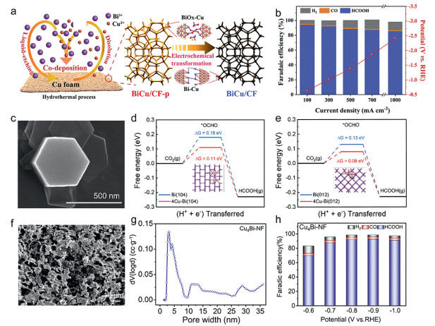
Morphological engineering further boosts performance. Copper-modified bismuth nitrate (Cu-BiOON4) hexagonal nanosheets (Fig. 12c) deliver FEformate of 100% at −0.6 V vs. RHE [143]. Membrane electrode assemblies (MEAs) maintain a stable current density of −80 mA/cm2 for 4 h during operation, directly producing formate solutions at concentrations of 0.2 mol/L. Minimal Cu doping enables the formed CuBi alloy after reduction to retain its hexagonal structure, ensuring dominant exposure of formate-selective Bi (012) and Bi (104) facets. This dual-configurational advantage accelerates interfacial electron transfer while decreasing *OCHO-to-formate conversion energy barriers (Figs. 12d and e). Advanced architectures like CuxBi-NF77 exploit metastable intermetallic phases and grain boundary-rich interfaces (Fig. 12f) [144], where hierarchical porosity synergizes with orbital hybridization to enhance mass transport and intermediate stabilization (Fig. 12g). This achieves concurrent activity enhancement and 92.4% formate selectivity (Fig. 12h). Collectively, these systems demonstrate how synergistic electronic modulation and controlled nanostructuring advance CO2 electrolysis benchmarks.
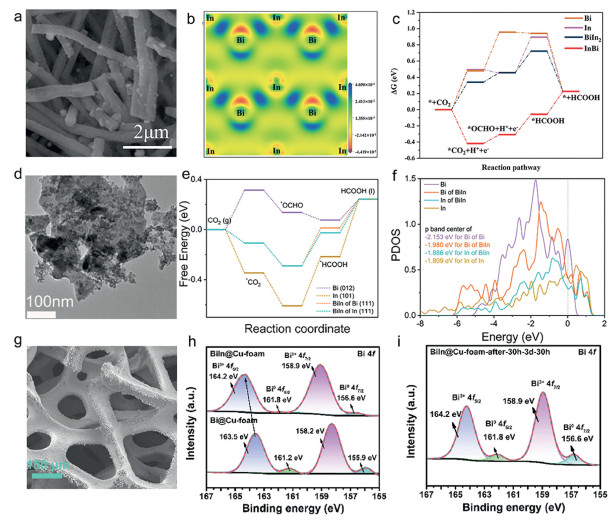
The strategic integration of In with Bi into Bi-In bimetallic systems advances CO2RR through synergistic combination these two components. A bimetallic Bi5In5 nanofiber (NF) catalyst synthesized via electrospinning and electrochemical reduction demonstrates exceptional performance, achieving FEformate of 96.8% with a formate production rate of 4.55 mmol h−1 cm−2 (Fig. 13a) [145]. Differential charge density analysis reveals a strong interaction between Bi and In atoms (Fig. 13b), which facilitates interfacial charge mobility and thermodynamically drives the CO2-to-HCOOH pathway from endothermic to exothermic (Fig. 13c). This electronic synergy enhances both catalytic activity and selectivity. Further optimization is achieved through the Bi/In-750 catalyst supported on Bi2O2CO3 nanosheets, which provides a hierarchical architecture with abundant CO2 adsorption sites (Fig. 13d) [146]. The alloying effect reduces the HCOO* adsorption energy (Fig. 13e) while elevating the density of states near the Fermi level (Fig. 13f), accelerating charge transfer kinetics to deliver a FEformate of 97.2%. Moreover, the introduction of In into the Bi@Cu-foam electrode effectively modulates the electronic structure of the Bi sites, stabilizing the active phase (Figs. 13g–i) [147]. This structural and electronic co-optimization enables the electrode to retain > 90% initial FEformate over 300 h of continuous operation, showcasing unparalleled durability for industrial-scale applications.
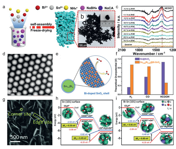
Recent advances in Sn-Bi bimetallic catalysts for CO2RR demonstrate validated design principles. Computational studies by Ren et al. identify optimized Sn-Bi interfacial configurations for formate pathway selectivity, providing theoretical basis for precision synthesis of tailored heterocatalytic systems [148]. Nanoporous Sn-Bi aerogels with branched nanowire architectures were synthesized through sodium borohydride reduction methodology, establishing interconnected three-dimensional conductive networks (Figs. 14a and b) [149]. The hierarchical porosity enhances electrolyte permeation and exposes dual-active sites, while in situ ATR-FTIR spectroscopy confirms Sn-Bi synergism stabilizes the HCOO* intermediate (Fig. 14c). This structural-electronic interplay enables efficient mass/charge transport critical for improved electrocatalytic performance. Further innovation emerged from Yang's group with the development of core-shell BixSn1-x@Bi-SnOx nanoparticles (Figs. 14d and e) [150]. The Bi doped SnOx shell selectively suppresses H2/CO evolution (Fig. 14f), while the engineered defect architecture and interfacial electronic synergy optimizes *OCHO adsorption geometry for the enhanced formate generation (Fig. 14g). DFT simulations elucidate interfacial functionality within Sn-Bi systems, quantifying the energetic stabilization of formate pathways relative to CO formation (Figs. 14h and i) [76]. This establishes a structure-activity paradigm for alloy-mediated CO2 reduction electrocatalysis.
Bi-based alloys incorporating both mainstream and noble metals demonstrate unique advantages in tailoring CO2 reduction pathways. The electrodeposited Bi-Sb bimetallic system on carbide paper exemplifies synergistic effects, where Sb integration modulates the electronic structure to lower *OCHO adsorption energy while suppressing competing CO pathways, thereby elevating formate selectivity [151]. Expanding beyond binary systems, ternary alloys such as Pb-Bi-Sn further optimize performance by introducing secondary metal dopants (e.g., Pb) that mitigate parasitic hydrogen evolution [152]. These multinary systems leverage elemental diversity to balance intermediate stabilization and side-reaction inhibition, illustrating the versatility of alloying strategies in catalyst design.
Bi-based alloy electrocatalysts achieve enhanced CO2-to-formate conversion through synergistic geometric and electronic effects. Interfacial charge redistribution at heteroatomic junctions (e.g., Bi-Cu, Bi-In, Bi-Sn) lowers activation barriers for key intermediates, while lattice mismatch engineering generates high-index facets and defect-rich interfaces optimizing active site density. Critical design guidelines include: (i) Optimizing secondary metal content to balance *OCHO adsorption and charge transfer, and (ii) engineering metastable intermetallic phases to sustain desired FEformate at high current densities. Theoretical and experimental studies demonstrate alloy catalysts universally outperform monometallic systems, elevating formate selectivity > 90% at industrial current densities (> 200 mA/cm2). Future development requires combinatorial phase diagram exploration through high-throughput workflows to establish structure-function databases, enabling machine learning-guided design of next-generation alloy systems targeting full potential in industrial CO2 electrolysis applications.
Electrocatalytic CO2-to-formate conversion emerges as a pivotal technology for sustainable carbon cycling. This review analyzes systematic advances in Bi-based electrocatalysts, covering metallic nanostructures, atomically dispersed configurations, functional compounds, rationally designed heterojunctions, and optimized bimetallic systems. Table 1 consolidates key performance metrics—including synthesis routes, operational conditions (electrolyte, current density, overpotential), Faradaic efficiency, and stability—for representative Bi-based catalysts, providing a benchmark for industrial scalability and future optimization efforts. Rational design principles—morphological engineering, electronic modulation, and interface control—collectively enhance performance by optimizing reaction pathways and charge transport. Fundamental insights reveal selective formate generation arises from electronic structure optimization stabilizing key OCHO*/HCOO* intermediates, complemented by synergistic dual-site interactions. Integrating operando characterization with computational modeling has elucidated dynamic catalyst restructuring mechanisms during operation. Despite achieving > 90% Faradaic efficiency, industrial implementation of bismuth catalysts demands unified performance benchmarks (≥90% FE at ≥300 mA/cm2, > 1000 h stability) with standardized protocols to address longevity and scalability constraints [153]. Future advancement hinges on integrating atomic-scale catalyst engineering with reactor innovation through machine learning-guided design, multimodal diagnostics, and system-level optimization—establishing closed-loop methodology for sustainable CO2 valorization.
 DownLoad:
CSV
DownLoad:
CSV
| Catalysts | Synthesis method | Electrolyte | Cell type | FE (%) | Current density (mA/cm2) | Potential (V vs. RHE) |
Stability (h) | Ref. |
| Bi NPs@PG | Thermal reduction | 0.1 mol/L KHCO3 | H cell | 87.0 | 49.2 | −1.11 | 17 | [66] |
| Bi NTs | Electroreduction | 1 mol/L KOH | Flow cell | 98.0 | ~200 | −0.56 | 11 | [67] |
| Bi nanosheets | Liquid-phase reduction | 0.05 mol/L H2SO4+ 3 mol/L KCl |
Flow cell | 92.2 | 237.1 | −1.23 | 8 | [74] |
| Bi-DC | Pyrolysis | 1 mol/L KHCO3 | Flow cell | 97.2 | ~100 | −0.86 | 20 | [77] |
| GC-D/Bi | Galvanic cell deposition | 1 mol/L KOH | Flow cell | 96.7 | ~90 | −0.92 | 40 | [79] |
| Bi PNS | Chemical reduction | 1 mol/L KOH | H cell | 95.2 | 72 | −1.40 | 10 | [80] |
| Bi nanoflowers | Chemical replacement | 0.1 mol/L KHCO3 | H cell | 92.3 | ~12 | −0.90 | 16 | [82] |
| Bi/BiOBr-D | Chemical reduction | 1 mol/L KOH | Flow cell | ~97 | 500 | / | 10 | [91] |
| C-Bi SACs | Laser agitation | 0.5 mol/L KHCO3 | H cell | 82.6 | ~25 | −0.95 | 40 | [93] |
| Bi SACs on N-doped C | Pyrolysis and etching | 0.1 mol/L KHCO3 | H cell | 95.1 | / | −1.10 | 10 | [94] |
| β-Bi2O3 | Thermal decomposition | 0.1 mol/L KHCO3 | H cell | 98.1 | ~12 | −1.10 | 36 | [96] |
| Bi2O3@LPC | Hydrothermal reaction | 1 mol/L KOH | Flow cell | 98.0 | 150 | −1.20 | 20 | [103] |
| V-doped Bi2O3 | Hydrothermal reaction | 0.5 mol/L KHCO3 | H cell | 94.2 | 45.0 | −1.10 | 22 | [106] |
| S-doped Bi2O3 | Electro-reconstruction | 0.5 mol/L KHCO3 | H cell | 92.0 | ~14 | −0.90 | 7 | [108] |
| Ov-Bi2O2CO3 | Electrodeposition | 0.5 mol/L KHCO3 | H cell | 90.2 | 16.5 | −0.68 | 7 | [118] |
| Cu-Bi2O2CO3 | Hydrothermal reaction | 1 mol/L KOH | Flow cell | 98.0 | 800 | / | 20 | [121] |
| S-doped Bi2O2CO3 | Hydrothermal reaction | 0.5 mol/L KHCO3 | H cell | 96.7 | 29.0 | −0.90 | 20 | [124] |
| BiOBr | Hydrothermal reaction | 1 mol/L KHCO3 | Flow cell | 91.0 | 148 | −1.05 | 9 | [125] |
| CT/h-BiOBr | Solvothermal reaction | 1 mol/L KOH | Flow cell | 97.0 | ~130 | −0.80 | 18 | [126] |
| Bi-Cu/HMCS | Chemical reduction | 0.1 mol/L KHCO3 | H cell | ~100 | 4.6 | −0.70 | 60 | [133] |
| PG/BiOCl1-x | Hydrothermal/ annealing |
0.1 mol/L KHCO3 | H cell | 92.8 | ~70 | −0.92 | 100 | [134] |
| Bi2S3-Bi2O3 | Wet chemical | 1 mol/L KOH | Flow cell | 95.0 | ~150 | −1.10 | / | [135] |
| Bi2O2CO3/ Bi2O3 |
Hydrothermal/ Mixing |
1 mol/L KOH | Flow cell | 98.1 | 60.8 | −0.80 | 40 | [137] |
| Bi0-Bi2O2CO3 | In-situ electroreduction | 1 mol/L KOH | Flow cell | 93.0 | 1900 | −0.95 | 100 | [138] |
| CuBi NSs | Wet chemical | 1 mol/L KOH | Flow cell | 96.0 | 230 | −1.0 | 10 | [143] |
| Cu-Bi nanofoam | Thermal shock | 0.1 mol/L KHCO3 | H cell | 92.4 | ~15 | −0.9 | 32 | [144] |
| In-Bi nanofiber | Electrospinning | 1 mol/L KOH | Flow cell | 96.8 | ~210 | −1.10 | / | [145] |
| Sn-Bi aerogel | Reduction/ gelation |
0.1 mol/L KHCO3 | H cell | 93.9 | ~9 | −1.0 | 10 | [149] |
| Sb-Bi nanoleaf | Electrodeposition | 0.5 mol/L KHCO3 | H cell | 88.3 | ~9 | −0.90 | 25 | [151] |
Future advancements in Bi-based electrocatalysts demand atomically precise control over active site configurations, extending beyond conventional nanostructuring to address fundamental limitations in stability and site accessibility under industrial operating conditions. While current synthesis methods enable morphological tuning (e.g., edge-rich Bi nanosheets), they lack the resolution to systematically engineer metastable coordination environments that govern *OCHO intermediate stabilization. Key opportunities involve atomic-precision regulation of electronic configurations through p-band center positioning and coordination number engineering, coupled with interfacial bifunctional ligand integration to suppress competing pathways.
A paradigm-shifting approach involves machine-learning accelerated atomic fabrication, integrating cryogenic electron tomography with real-time electrochemical strain monitoring to dynamically map vacancy formation energies. Such techniques could resolve the critical yet unresolved trade-off between vacancy concentration and structural integrity—a key determinant of catalyst longevity at > 500 mA/cm2 current densities. Implementing in situ atomic layer deposition with potential-dependent feedback control represents a transformative pathway to construct precisely coordinated Bi-O-C interfaces, circumventing the random reconstruction processes that currently limit durability beyond 200 h of operation. Bridging these advances requires reactor engineering innovations addressing microenvironmental pH gradients and membrane durability constraints. This atomic-scale engineering paradigm provides the foundation for sustainable CO2 electrocatalysis.
Resolving atomic-scale mechanisms governing CO2-to-formate conversion remains fundamental for rational catalyst design. Despite established two-electron pathways via HCOO* intermediates, critical mechanistic uncertainties persist, particularly regarding dynamic catalyst reconstruction under operation, solvation-mediated proton-coupled electron transfer kinetics, and potential-driven selectivity switching. These complexities arise from intertwined electronic properties (p-band alignment, frontier orbital occupancy) and interfacial phenomena (local proton concentration, double-layer restructuring), further complicated by competing hydrogen evolution pathways.
Decoding the dynamic interfacial processes during CO2RR requires multimodal operando diagnostics that simultaneously track atomic rearrangement, proton flux, and intermediate evolution at sub-millisecond resolution. While existing techniques like in situ Raman and XAFS have revealed phase transformations, they cannot capture the transient Bi3+/Bi0 redox couples governing proton-coupled electron transfer. We propose integrating femtosecond XAFS with electrochemical surface plasmon resonance imaging to quantify the electric double layer restructuring during *OCHO formation. This could resolve the long-debated role of interfacial water networks in the critical hydrogenation step—a mechanistic black box highlighted by kinetic isotope effects. These multimodal approaches enable correlated spatial-temporal mapping across Å-to-µm and millisecond-to-hour domains. Concurrently, reactive force-field molecular dynamics simulations incorporating explicit electric fields should model potential-dependent solvation sheath dynamics, bridging the gap between computed adsorption energies and experimental Tafel slopes. Such multidimensional analysis would establish predictive descriptors linking Bi 6p-band centers to proton transfer barriers, enabling rational suppression of parasitic HER at low overpotentials.
Industrial deployment of Bi-based CO2 electroreduction requires advanced electrolyzer engineering beyond conventional H-cell configurations. While MEAs now achieve industrial-level current densities through innovations like tunable hydrophobicity gas diffusion electrodes and corrosion-resistant anion exchange membranes, persistent challenges impede commercialization. Key limitations include carbonate-induced membrane failure during extended operation, CO2 distribution inhomogeneity in scaled systems, and critical flooding/salt precipitation issues in alkaline flow cells—evidenced by > 20% performance decay within 100 h for state-of-the-art catalysts under industrial conditions.
Addressing these limitations necessitates integrated catalyst-electrolyzer co-design with quantifiable industrial benchmarks. Future research demands simultaneous optimization of three key areas: alkali-stable anion-exchange membranes (e.g., poly(fluorene)-based polymers) to mitigate carbonate precipitation, mechanically reinforced gas diffusion electrodes incorporating PTFE/carbon composites to prevent flooding and catalyst detachment, and pulsed electrolysis protocols informed by in situ diagnostics to counteract local pH gradients. Concurrently, innovative approaches include electrolyte-phobic surface functionalization of Bi catalysts to repel water while preserving active sites, and cation-blocking interlayers engineered through atomic doping (F−, PO43−) to inhibit carbonate nucleation. These strategies must align with the dynamic reconstruction behavior of Bi catalysts under industrial current densities.
Ultimately realizing commercially viable systems requires reconciling performance metrics with economic parameters through rigorous co-design validation. Industrial implementation benchmarks must include current densities exceeding 500 mA/cm2 in MEAs, system-level energy efficiency > 50% (cell voltage < 3.5 V), continuous operation > 1000 h with < 10% activity decay, and CO2 utilization efficiency > 70%. Achieving these targets entails developing hierarchical electrode architectures for uniform current distribution, optimizing ionomer-catalyst interfaces to reduce ionic resistance, and establishing predictive stability models correlating accelerated stress tests with long-term performance. System validation must prioritize scalability in > 500 cm2 electrolyzers to ensure economic viability for grid-compatible deployment.
The authors declare that they have no known competing financial interests or personal relationships that could have appeared to influence the work reported in this paper.
Xiaoli Zhao: Writing – review & editing, Writing – original draft, Resources, Methodology, Investigation. Lijuan Yang: Visualization, Investigation, Formal analysis. Yong Hao: Writing – original draft, Investigation, Formal analysis. Yi Cheng: Investigation, Formal analysis. Fei Li: Writing – review & editing, Resources, Investigation. Xinghua Zhu: Writing – review & editing, Investigation, Formal analysis. Ming Huang: Writing – review & editing, Methodology, Funding acquisition, Conceptualization.
This work was supported by the National Natural Science Foundation of China (Nos. 52373223 and 52202215), and Sichuan Science and Technology Program (No. 2025NSFTD0003).
W.J. Dong, I.A. Navid, Y. Xiao, et al., J. Mater. Chem. A 10 (2022) 7869–7877. doi: 10.1039/d2ta00032f
B. Chen, H. Kildahl, H. Yang, et al., J. Energy. Chem. 90 (2024) 464–485. doi: 10.1016/j.jechem.2023.11.041
D. Ewis, M. Arsalan, M. Khaled, et al., Sep. Purif. Technol. 316 (2023) 123811. doi: 10.1016/j.seppur.2023.123811
S. Chen, Y. Su, P. Deng, et al., ACS Catal. 10 (2020) 4640–4646. doi: 10.1021/acscatal.0c00847
M. Sun, Y. Ma, Y. Tan, et al., SusMat 5 (2025) e70011. doi: 10.1002/sus2.70011
Q. Guo, T. Lan, Z. Su, et al., Mater. Rep.: Energy 3 (2023) 100172.
Z. Li, B. Sun, D. Xiao, et al., Angew. Chem. Int. Ed. 62 (2023) e202217569. doi: 10.1002/anie.202217569
R. Yang, L. Xia, W. Jiang, et al., Adv. Energy. Mater. 15 (2025) 2405964. doi: 10.1002/aenm.202405964
Q. Cheng, M. Huang, L. Xiao, et al., ACS Catal. 13 (2023) 4021–4029. doi: 10.1021/acscatal.2c06228
W. Kwon, D. Kim, Y. Lee, et al., Exploration (2025) e20240019.
K. Wang, D. Liu, P. Deng, et al., Nano. Energy 64 (2019) 103954. doi: 10.1016/j.nanoen.2019.103954
F. Wang, W. Zhang, H. Wan, et al., Chin. Chem. Lett. 33 (2022) 2259–2269. doi: 10.1016/j.cclet.2021.08.074
I. Sullivan, A. Goryachev, I.A. Digdaya, et al., Nat. Catal. 4 (2021) 952–958. doi: 10.1038/s41929-021-00699-7
L. Gubler, Nat. Energy 7 (2022) 216–217. doi: 10.1038/s41560-022-00983-1
L. Ge, H. Rabiee, M. Li, et al., Chem 8 (2022) 663–692. doi: 10.1016/j.chempr.2021.12.002
K. Sun, M. Tebyetekerwa, H. Zhang, et al., Adv. Energy. Mater. 14 (2024) 2400625. doi: 10.1002/aenm.202400625
C. Wang, Z. Lv, X. Feng, et al., Adv. Energy. Mater. 14 (2024) 2400160. doi: 10.1002/aenm.202400160
T. Liu, Y. Wang, Y. Wu, et al., Nat. Commun. 15 (2024) 10920. doi: 10.1038/s41467-024-55334-3
Q. Cheng, M. Huang, Q. Ye, et al., Chin. Chem. Lett. 35 (2024) 109112. doi: 10.1016/j.cclet.2023.109112
C. Qin, X. Li, T. Wang, et al., Exploration 5 (2025) 270011. doi: 10.1002/EXP.70011
R. Lu, Y. Liu, Z. Wang, EcoEnergy 2 (2024) 695–713. doi: 10.1002/ece2.67
H.N.N. Tran, W. Li, X. Liu, Chem. Eng. J. 500 (2024) 156613. doi: 10.1016/j.cej.2024.156613
E.P. Komarala, A.A. Alkhoori, X. Zhang, et al., J. Energy. Chem. 86 (2023) 246–262. doi: 10.1016/j.jechem.2023.07.032
G.H. Han, J. Bang, G. Park, et al., Small 19 (2023) 2205765. doi: 10.1002/smll.202205765
J. Wang, J. Wang, J. Feng, et al., Joule 8 (2024) 3126–3141. doi: 10.1016/j.joule.2024.08.007
L. Zhang, A.V. Müller, S.P. Desai, et al., ACS Catal. 14 (2024) 18477–18487. doi: 10.1021/acscatal.4c03845
Y. Liu, F. Wang, Z. Jiao, et al., Electrochem. Energy. Rev. 5 (2022) 5. doi: 10.1007/s41918-022-00132-y
Z. Wu, W. Cheng, X. Wang, et al., Front. Energy 19 (2025) 435–449. doi: 10.1007/s11708-024-0968-y
K. Fan, Y. Jia, Y. Ji, et al., ACS Catal. 10 (2020) 358–364. doi: 10.1021/acscatal.9b04516
X. Wang, D. Wu, X. Kang, et al., J. Energy. Chem. 71 (2022) 159–166. doi: 10.6023/a21090441
Y. Kuang, H. Rabiee, L. Ge, et al., Energy. Environ. Mater. 6 (2023) e12596. doi: 10.1002/eem2.12596
Z. Nie, L. Yu, L. Jiang, et al., Carbon. Neutralization 2 (2023) 458–466. doi: 10.1002/cnl2.66
C. Fang, L. Huang, W. Gao, et al., Adv. Energy. Mater. 14 (2024) 2400813. doi: 10.1002/aenm.202400813
Z. Pan, Z. Zhang, W. Li, et al., ACS Energy Lett. 8 (2023) 3742–3749. doi: 10.1021/acsenergylett.3c01165
G. Wang, F. Wang, P. Deng, et al., Mater. Rep.: Energy 3 (2023) 100181.
N. Han, P. Ding, L. He, et al., Adv. Energy. Mater. 10 (2020) 1902338. doi: 10.1002/aenm.201902338
P. Li, F. Yang, J. Li, et al., Adv. Energy. Mater. 13 (2023) 2301597. doi: 10.1002/aenm.202301597
Y. Wang, Y. Li, J. Liu, et al., Angew. Chem. Int. Ed. 60 (2021) 7681–7685. doi: 10.1002/anie.202014341
M. Aman, V. Sharma, S. Omar, Appl. Surf. Sci. 670 (2024) 160611. doi: 10.1016/j.apsusc.2024.160611
P.F. Sui, M.R. Gao, S. Liu, et al., Adv. Funct. Mater. 32 (2022) 2203794. doi: 10.1002/adfm.202203794
X. Ma, Q. Wang, M. Wang, et al., Chem. Eng. J. 474 (2023) 145711. doi: 10.1016/j.cej.2023.145711
J. Chen, T. Mao, J. Wang, et al., Angew. Chem. Int. Ed. 63 (2024) e202408849. doi: 10.1002/anie.202408849
L. Yi, J. Chen, P. Shao, et al., Angew. Chem. Int. Ed. 59 (2020) 20112–20119. doi: 10.1002/anie.202008316
X. Chen, R. Lu, C. Li, et al., Nat. Commun. 16 (2025) 1927. doi: 10.1038/s41467-025-56975-8
H. Liu, Y. Bai, M. Wu, et al., Angew. Chem. Int. Ed. 63 (2024) e202411575. doi: 10.1002/anie.202411575
C. Yang, J. Chai, Z. Wang, et al., Chem. Res. Chin. Univ. 36 (2020) 410–419. doi: 10.1007/s40242-020-0069-3
Z. Chen, L. Fei, W. Jia-Jun, et al., Microstructures 5 (2025) 2025016.
Z. Yang, Y. Jin, Z. Feng, et al., ChemSusChem 18 (2025) e202401181. doi: 10.1002/cssc.202401181
W. Zhang, B. Jia, X. Liu, T. Ma, SmartMat 3 (2022) 5–34. doi: 10.1002/smm2.1090
J. Lin, Y. Zhang, P. Xu, L. Chen, Mater. Rep.: Energy 3 (2023) 100194.
B. Zhang, Y. Jiang, M. Gao, et al., Nano. Energy 80 (2021) 105504. doi: 10.1016/j.nanoen.2020.105504
L. Fan, C. Xia, P. Zhu, et al., Nat. Commun. 11 (2020) 3633. doi: 10.1038/s41467-020-17403-1
S. Gao, Y. Lin, X. Jiao, et al., Nature 529 (2016) 68–71. doi: 10.1038/nature16455
M. Zhang, M. Lu, M.Y. Yang, et al., eScience 3 (2023) 100116. doi: 10.1016/j.esci.2023.100116
F. Chen, Z.C. Yao, Z.H. Lyu, et al., eScience 4 (2024) 100172. doi: 10.1016/j.esci.2023.100172
B. Deng, M. Huang, K. Li, et al., Angew. Chem. Int. Ed. 61 (2022) e202114080. doi: 10.1002/anie.202114080
Z. Chen, T. Wang, B. Liu, et al., J. Am. Chem. Soc. 142 (2020) 6878–6883. doi: 10.1021/jacs.0c00971
P. Ding, H. Zhao, T. Li, et al., J. Mater. Chem. A 8 (2020) 21947–21960. doi: 10.1039/d0ta08393c
J. Fan, X. Zhao, X. Mao, et al., Adv. Mater. 33 (2021) 2100910. doi: 10.1002/adma.202100910
Q. Huang, Z. Qian, N. Ye, et al., Adv. Mater. 37 (2025) 2415639. doi: 10.1002/adma.202415639
D. Xia, H. Yu, H. Xie, et al., Nanoscale 14 (2022) 7957–7973. doi: 10.1039/d2nr01900k
M.F. Liu, C. Zhang, J. Wang, et al., Chem. Eur. J. 30 (2024) e202303711. doi: 10.1002/chem.202303711
X. Zhang, J. Fu, Y. Liu, et al., ACS Sustain. Chem. Eng. 8 (2020) 4871–4876. doi: 10.1021/acssuschemeng.0c00099
B. Zhang, G. Yang, Q. Chai, et al., Sustain. Mater. Technol. 41 (2024) e01042.
H. Rabiee, L. Ge, X. Zhang, et al., Appl. Catal. B 286 (2021) 119945. doi: 10.1016/j.apcatb.2021.119945
Y. Cheng, R. Yang, L. Xia, et al., Nanoscale 16 (2024) 2373–2381. doi: 10.1039/d3nr05853k
Q. Gong, P. Ding, M. Xu, et al., Nat. Commun. 10 (2019) 2807. doi: 10.1038/s41467-019-10819-4
X. Yang, P. Deng, D. Liu, et al., J. Mater. Chem. A 8 (2020) 2472–2480. doi: 10.1039/c9ta11363k
Z. Liu, Q. Fan, H. Huo, et al., Sci. China. Chem. 67 (2024) 2190–2198. doi: 10.1007/s11426-024-2112-2
G. Piao, S.H. Yoon, D.S. Han, H. Park, ChemSusChem 13 (2020) 698–706. doi: 10.1002/cssc.201902581
T. Yuan, Z. Hu, Y. Zhao, et al., Nano. Lett 20 (2020) 2916–2922. doi: 10.1021/acs.nanolett.0c00844
D. Wu, J. Liu, Y. Liang, et al., ChemSusChem 12 (2019) 4700–4707. doi: 10.1002/cssc.201901724
B. Liu, Y. Xie, X. Wang, et al., Appl. Catal. B 301 (2022) 120781. doi: 10.1016/j.apcatb.2021.120781
Y. Qiao, W. Lai, K. Huang, et al., ACS Catal. 12 (2022) 2357–2364. doi: 10.1021/acscatal.1c05135
Y.C. He, D.D. Ma, S.H. Zhou, et al., Small 18 (2022) 2105246. doi: 10.1002/smll.202105246
G. Wen, D.U. Lee, B. Ren, et al., Adv. Energy. Mater. 8 (2018) 1802427. doi: 10.1002/aenm.201802427
W. Li, C. Yu, X. Tan, et al., ACS Catal. 14 (2024) 8050–8061. doi: 10.1021/acscatal.4c01519
Z.H. Zhao, J.R. Huang, D.S. Huang, et al., J. Am. Chem. Soc. 146 (2024) 14349–14356. doi: 10.1021/jacs.4c04841
J. Chen, S. Chen, Y. Li, et al., Small 18 (2022) 2201633. doi: 10.1002/smll.202201633
X. Fu, J.A. Wang, X. Hu, et al., Adv. Funct. Mater. 32 (2022) 2107182. doi: 10.1002/adfm.202107182
A. Chen, X. Dong, J. Mao, et al., Appl. Catal. B 333 (2023) 122768. doi: 10.1016/j.apcatb.2023.122768
S. Yang, M. Jiang, W. Zhang, et al., Adv. Funct. Mater. 33 (2023) 2301984. doi: 10.1002/adfm.202301984
J. Su, L. Zhuang, S. Zhang, et al., Chin. Chem. Lett. 32 (2021) 2947–2962. doi: 10.1016/j.cclet.2021.03.082
H. Wang, X. Li, Y. Deng, et al., Coord. Chem. Rev. 529 (2025) 216462. doi: 10.1016/j.ccr.2025.216462
S.M. Wu, P. Schmuki, Adv. Mater. 37 (2025) 2414889. doi: 10.1002/adma.202414889
X. Bai, J. Guan, Small Struct. 4 (2023) 2200354. doi: 10.1002/sstr.202200354
M.B. Gawande, K. Ariga, Y. Yamauchi, Small 17 (2021) 2101584. doi: 10.1002/smll.202101584
X. Yang, Y. Chen, L. Qin, et al., ChemSusChem 13 (2020) 6307–6311. doi: 10.1002/cssc.202001609
E. Zhang, T. Wang, K. Yu, et al., J. Am. Chem. Soc. 141 (2019) 16569–16573. doi: 10.1021/jacs.9b08259
Y. Jiang, J. Shan, P. Wang, et al., ACS Catal. 13 (2023) 3101–3108. doi: 10.1021/acscatal.3c00123
H. Zhao, Y. Xie, B. Lv, et al., Appl. Catal. B 371 (2025) 125234. doi: 10.1016/j.apcatb.2025.125234
H. Huang, Y. Wang, S. Zhang, et al., ACS Nano 19 (2025) 15509–15521. doi: 10.1021/acsnano.4c16236
M.N. Zhu, H. Jiang, B. -W. Zhang, et al., ACS Nano 17 (2023) 8705–8716. doi: 10.1021/acsnano.3c01897
J. Zhang, K. Zhao, Y. Ma, et al., Small Struct. 5 (2024) 2300323. doi: 10.1002/sstr.202300323
G. Fu, Y. He, Y. Zhang, et al., Energy. Convers. Manage. 117 (2016) 520–527. doi: 10.1016/j.enconman.2016.03.065
P.F. Sui, M.R. Gao, R. Feng, et al., Chem Catal. 3 (2023) 100842.
L. Li, S. Yao, Y. Feng, et al., Appl. Catal. B 372 (2025) 125302. doi: 10.1016/j.apcatb.2025.125302
H. Wen, Z. Zhao, Z. Luo, C. Wang, ChemSusChem 17 (2024) e202301859. doi: 10.1002/cssc.202301859
X.H. Huang, X.K. Yang, L. Gui, et al., Carbon 226 (2024) 119132. doi: 10.1016/j.carbon.2024.119132
F. Besharat, F. Ahmadpoor, Z. Nezafat, et al., ACS Catal. 12 (2022) 5605–5660. doi: 10.1021/acscatal.1c05728
G. Liu, X. Li, M. Liu, et al., SusMat 3 (2023) 834–842. doi: 10.1002/sus2.167
T. Tran-Phu, R. Daiyan, Z. Fusco, et al., Adv. Funct. Mater. 30 (2020) 1906478. doi: 10.1002/adfm.201906478
S. Zhang, X. Wang, D. Song, et al., Carbon. N. Y 228 (2024) 119385. doi: 10.1016/j.carbon.2024.119385
M. Zhou, Z. Guo, M. Wang, et al., J. Colloid. Interface Sci. 678 (2025) 309–316. doi: 10.1016/j.jcis.2024.09.116
Y. Fan, X. Yang, E. Wei, et al., Appl. Catal. B 345 (2024) 123716. doi: 10.1016/j.apcatb.2024.123716
G. Zhang, X. Zheng, X. Cui, et al., ACS Appl. Nano. Mater. 5 (2022) 15465–15472. doi: 10.1021/acsanm.2c03503
S.Q. Liu, M.R. Gao, R.F. Feng, et al., ACS Catal. 11 (2021) 7604–7612. doi: 10.1021/acscatal.1c01899
Q. Zheng, S. Luan, Y. Feng, et al., J. Power. Sources 601 (2024) 234298. doi: 10.1016/j.jpowsour.2024.234298
L. Wang, W.K. Gui, S. Jiang, et al., Rare. Met. 43 (2024) 3391–3399. doi: 10.1007/s12598-024-02665-1
A. Ma, Y. Lee, D. Seo, et al., Adv. Sci. 11 (2024) 2400874. doi: 10.1002/advs.202400874
Y. Ding, Y. Li, L. Wang, et al., ACS Appl. Energy. Mater. 7 (2024) 5418–5425. doi: 10.1021/acsaem.4c00716
Y. Li, J. Chen, S. Chen, et al., Appl. Catal. B 349 (2024) 123874. doi: 10.1016/j.apcatb.2024.123874
Z. Jiang, S. Ren, X. Cao, et al., Angew. Chem. Int. Ed. 63 (2024) e202408412. doi: 10.1002/anie.202408412
W. Zhou, H. Yang, N. Gao, et al., J. Alloys. Compd. 903 (2022) 163707. doi: 10.1016/j.jallcom.2022.163707
X. Wang, Q. Zhang, C. Wang, et al., Appl. Surf. Sci. 669 (2024) 160453. doi: 10.1016/j.apsusc.2024.160453
W.S. Cho, D.M. Hong, W.J. Dong, et al., Energy Environ. Mater. 7 (2024) e12490. doi: 10.1002/eem2.12490
J. Ma, J. Yan, J. Xu, et al., Chem. Eng. J. 455 (2023) 140926. doi: 10.1016/j.cej.2022.140926
X. Chen, J. Chen, H. Chen, et al., Nat. Commun. 14 (2023) 751. doi: 10.1038/s41467-023-36263-z
Y. Zhang, Y. Chen, R. Liu, et al., InfoMat 5 (2023) e12375. doi: 10.1002/inf2.12375
H. Liu, Z. Wang, Y. He, et al., Appl. Catal. B 361 (2025) 124667. doi: 10.1016/j.apcatb.2024.124667
J. Lu, Y. Ren, J. Liang, et al., Small 20 (2024) 2402879. doi: 10.1002/smll.202402879
S. Zhang, X. Zhang, J. Yang, et al., Chem. Commun. 61 (2025) 1219–1222. doi: 10.1039/D4CC05306K
A. He, C. Wang, N. Zhang, et al., Appl. Surf. Sci. 638 (2023) 158140. doi: 10.1016/j.apsusc.2023.158140
J. Wang, J. Mao, X. Zheng, et al., Appl. Surf. Sci. 562 (2021) 150197. doi: 10.1016/j.apsusc.2021.150197
S. Yang, H. An, S. Arnouts, et al., Nat. Catal. 6 (2023) 796–806. doi: 10.1038/s41929-023-01008-0
Y. Chen, Y. Zhang, Z. Li, et al., ACS Nano 18 (2024) 19345–19353. doi: 10.1021/acsnano.4c06019
K. Meesombad, K. Srisawad, P. Khemthong, et al., ACS Appl. Nano. Mater. 7 (2024) 20046–20057. doi: 10.1021/acsanm.4c02570
S. Pal, T. Ahmed, S. Khatun, P. Roy, ACS Appl. Energy. Mater. 6 (2023) 7737–7784. doi: 10.1021/acsaem.3c01058
Y. Yuan, Q. Wang, Y. Qiao, et al., Adv. Energy. Mater. 12 (2022) 2200970. doi: 10.1002/aenm.202200970
F. Yang, W. Zhang, X. Ma, D. Zhang, J. Electrochem. Soc. 169 (2022) 044524. doi: 10.1149/1945-7111/ac6703
T. Dou, D. Song, Y. Wang, et al., Nano Res. 17 (2024) 3644–3652. doi: 10.1007/s12274-023-6247-0
S. Chang, Y. Xuan, J. Duan, K. Zhang, Appl. Catal. B 306 (2022) 121135. doi: 10.1016/j.apcatb.2022.121135
X. Wang, M. Zhou, M. Wang, et al., Nano Lett. 23 (2023) 10946–10954. doi: 10.1021/acs.nanolett.3c03173
Y. Hao, Y. Cheng, J. Wang, et al., Appl. Catal. B 376 (2025) 125472. doi: 10.1016/j.apcatb.2025.125472
P.F. Sui, C. Xu, M.N. Zhu, et al., Small 18 (2022) 2105682. doi: 10.1002/smll.202105682
B. Li, J. Chen, L. Wang, et al., Adv. Sci. 12 (2025) 2415616. doi: 10.1002/advs.202415616
X. Ren, F. Liu, H. Wu, et al., Angew. Chem. Int. Ed. 63 (2024) e202316640. doi: 10.1002/anie.202316640
L. Lin, X. He, X.G. Zhang, et al., Angew. Chem. Int. Ed. 62 (2023) e202214959. doi: 10.1002/anie.202214959
S. Nitopi, E. Bertheussen, S.B. Scott, et al., Chem. Rev. 119 (2019) 7610–7672. doi: 10.1021/acs.chemrev.8b00705
C. Xiao, J. Zhang, ACS Nano 15 (2021) 7975–8000. doi: 10.1021/acsnano.0c10697
Q. Xie, G.O. Larrazábal, M. Ma, et al., J. Energy. Chem. 63 (2021) 278–284. doi: 10.1016/j.jechem.2021.09.008
H. Lv, L. Lin, X. Zhang, et al., Nat. Commun. 12 (2021) 5665. doi: 10.1038/s41467-021-26001-8
X. Wang, X. Fei, M. Wang, et al., J. Mater. Chem. A 10 (2022) 23542–23550. doi: 10.1039/d2ta06843e
S. Yang, H. Wang, Y. Xiong, et al., Nano Lett. 23 (2023) 10140–10147. doi: 10.1021/acs.nanolett.3c02380
Y. Li, Y. Jin, X. Zong, et al., J. Mater. Chem. A 11 (2023) 11445–11453. doi: 10.1039/d3ta01481a
Q. Wang, X. Yang, H. Zang, et al., Small 19 (2023) 2303172. doi: 10.1002/smll.202303172
H. He, C. Yang, L. Deng, et al., J. Energy Chem. 99 (2024) 703–711. doi: 10.1016/j.jechem.2024.07.059
B. Ren, G. Wen, R. Gao, et al., Nat. Commun. 13 (2022) 2486. doi: 10.1038/s41467-022-29861-w
Z. Wu, H. Wu, W. Cai, et al., Angew. Chem. Int. Ed. 60 (2021) 12554–12559. doi: 10.1002/anie.202102832
Q. Yang, Q. Wu, Y. Liu, et al., Adv. Mater. 32 (2020) 2002822. doi: 10.1002/adma.202002822
C. Yang, Y. Hu, S. Li, et al., ACS Appl. Mater. Interfaces 15 (2023) 6942–6950. doi: 10.1021/acsami.2c20593
A.S. Kumawat, A. Sarkar, SN Appl. Sci. 1 (2019) 317. doi: 10.1007/s42452-019-0313-y
J. Xiao, D.D. Ma, X. Shen, et al., Appl. Catal. A 703 (2025) 120362. doi: 10.1016/j.apcata.2025.120362

Figure 1 CO2RR-to-products and corresponding thermodynamic equilibrium potentials. Reproduced with permission [49]. Copyright 2022, Wiley-VCH GmbH.

Figure 2 (a) Reaction pathways of CO2RR to CO and HCOOH/HCOO−. Reproduced with permission [51]. Copyright 2021, Elsevier Ltd. (b) Proposed calculated free energy profiles for CO2 reduction pathways on bismuth catalysts, demonstrating thermodynamic preference for formate production.

Figure 3 (a) Schematic illustration showing the synthesis of Bi-DC catalyst for CO2RR-to-formate. (b) FEformate of Bi-DC, Bi2O3 NS, and commercial Bi catalysts at various potentials. Reproduced with permission [77]. Copyright 2024, American Chemical Society. (c) Atomic structure of Bi-HHTP. (d) FEformic acid and current densities under different cell voltages in high-purity and diluted CO2 atmospheres. Reproduced with permission [78]. Copyright 2024, American Chemical Society. (e) Galvanic-cell deposition process for GC-D/Bi. (f) corresponding TEM image. (g) FEs for the products of GC-D/Bi at various potentials. Reproduced with permission [79]. Copyright 2022, Wiley-VCH GmbH.

Figure 4 (a) Illustration showing the synthetic procedure for porous Bi nanosheets. (b) Free energy profiles for formate formation on Bi (012), ideal Bi (001) and Bi (001) GB. Reproduced with permission [80]. Copyright 2022, Wiley-VCH GmbH. (c) Schematic for the preparation of Bi HF. (d) Free energy profiles for catalysts with contractive and normal Bi-Bi bonds. Reproduced with permission [81]. Copyright 2023, Elsevier Ltd. (e) Synthetic process of Bi-NFs on Cu foil. (f) FEs of the products on Bi-NFs at different potentials. Reproduced with permission [82]. Copyright 2023, Wiley-VCH GmbH.

Figure 5 (a) Schematic for the preparation of M-SnO2. (b) FEformate comparison. Reproduced with permission [90]. Copyright 2023, American Chemical Society. (c) Electronic coupling among Bi site and *OCHO intermediate. (d) Bi-p band center of Bi/BiOBr-D. Reproduced with permission [91]. Copyright 2025, Elsevier Ltd. (e) EXAFS spectra of Bi0.2 ML@Pd/C. (f) Atomic configurations of HCOO*, HCOO*-Bi and HC(O*-Bi)2 on Pd (110) surface, and free energy diagrams. (g) FE of H2 and concentration of HCOO− as a function of applied potentials. Reproduced with permission [92]. Copyright 2025, American Chemical Society. (h) Fourier transformed k3-weighted EXAFS spectra of Bi-C, Bi-NC, Bi2O3 and Bi. (i) Schematic of CO2RR on Bi-NC and Bi-C. Reproduced with permission [93]. Copyright 2023, American Chemical Society. (j) Production rates for formate of different catalysts. (k) Free energy diagrams calculated at a potential of −0.8 V. Reproduced with permission [94]. Copyright 2024, Wiley-VCH GmbH.

Figure 6 (a) TEM image of β-Bi2O3. (b) H/D Isotope effect of α-Bi2O3 and β-Bi2O3 conducted at −1.0 V vs. RHE. (c) In situ Raman spectra of α-Bi2O3 and β-Bi2O3. Reproduced with permission [96]. Copyright 2023, Elsevier Ltd. (d) HRTEM image β-Bi2O3. (e, f) In situ XRD patterns and in situ Raman spectra during CO2RR. (g) FEformate at different applied potentials. (h) Formate yield and energy efficiency at different applied potentials. Reproduced with permission [97]. Copyright 2025, Elsevier Ltd.

Figure 7 (a) Schematic showing preparation process of Bi2O3 fractal films on carbon fiber papers (CFP). (b, c) Cross-section and top-view SEM images of Bi2O3. Reproduced with permission [102]. Copyright 2020, Wiley-VCH GmbH. (d) HAADF-STEM image of Bi2O3@13–20 LPC. (e, f) Charge difference distribution and planar averaged electron density difference Δρ(z) of Bi2O3-NC4/C and Bi2O3-NC4/C (N-O) catalysts. Reproduced with permission [103]. Copyright 2024, Elsevier Ltd. (g) Schematic for the synthesis of Bi2O3/PC. (h) Free energy diagrams for CO2RR-to-formate. Reproduced with permission [104]. Copyright 2025, Elsevier Ltd.

Figure 8 (a) Schematic illustration showing the synthetic procedure of BOC-x NWs for CO2RR. Reproduced with permission [115]. Copyright 2024, Elsevier Ltd. (b) SEM image of BOC petal. (c, d) Free energy diagrams of CO2RR-to-HCOOH on BOC and R-BOC catalysts with or without strain. Reproduced with permission [116]. Copyright 2024, Wiley-VCH GmbH. (e) SEM image of BiOI. (f) Interlayer spacings of BiOX catalysts. Reproduced with permission [117]. Copyright 2023, Elsevier Ltd.

Figure 9 (a) Schematic shows the reaction pathways and the role of oxygen vacancy (VO) in CO2RR. (b) Free energy, ΔµOH−w, and the adsorption energies of OH* and H2O* for BOC with different VO contents. Reproduced with permission [118]. Copyright 2023, Springer Nature. (c) O 1s XPS spectra of Vo-BOC-NS and commercial BOC. (d) Corresponding 2D electron localization function (ELF) of Bi2O2CO3 with oxygen vacancy. (e) Charge density difference. Reproduced with permission [119]. Copyright 2023, Wiley-VCH GmbH. (f) EPR spectra of OV-poor and OV-rich BOC. (g, h) Operando ATR-FTIR spectra for CO2RR at various potentials on bare BOC and OV-rich BOC. Reproduced with permission [120]. Copyright 2025, Elsevier Ltd.

Figure 10 Time-dependent in situ XRD patterns at a fixed potential of −1.15 V vs. RHE of (a) BOBr, (b) BOCl, and (c) BOI. Reproduced with permission [125]. Copyright 2023, Springer Nature. (d) In situ XRD pattern, and (e) in situ Raman spectra of CT/h-BiOBr. (f) Atomic models of Bi (110) and Bi (110)-CTAB. Reproduced with permission [126]. Copyright 2024, American Chemical Society. (g) Structural transformation of BiOI to Bi2O2CO3. Reproduced with permission [127]. Copyright 2024, American Chemical Society.

Figure 11 (a) SEM image of Nafion/Bi@Cu-foam. (b, c) Gibbs free energies of formate formation and atomic configurations of reaction intermediates. Reproduced with permission [132]. Copyright 2022, Elsevier Ltd. (d) SEM image of Bi-Cu/HMCS catalyst. (e) C K-edge NEXAFS spectra of Bi-Cu/HMCS and HMCS. (f) Schematic of the Cu bridge effect in the C-Cu-Bi ternary system. Reproduced with permission [133]. Copyright 2023, American Chemical Society. (g) SEM image of PG/BiOCl1-x. Operando ATR-SEIRAS spectra of (h) BiOCl and (i) PG/BiOCl1-x catalysts during CO2RR. Reproduced with permission [134]. Copyright 2025, Elsevier Ltd. (j) SEM image of Bi2S3-Bi2O3 NSs. (k) Comparison of the-state-of-the-art Bi-based electrocatalysts with FEformate over 90%. (l) Schematic showing the band alignment of Bi2S3- Bi2O3 NSs. Reproduced with permission [135]. Copyright 2022, Wiley-VCH GmbH.

Figure 12 (a) Synthetic procedure of BiCu/CF. (b) Current-dependent FEs of HCOOH, CO, and H2 and the corresponding working potentials. Reproduced with permission [73]. Copyright 2022, Elsevier Ltd. (c) SEM image of Cu-BiOON4. (d, e) Free energy diagrams for HCOOH formation on Bi and 4Cu-Bi surfaces. Reproduced with permission [143]. Copyright 2022, Royal Society of Chemistry. (f, g) SEM image and pore distribution of Cu4Bi-NF. (h) FEs of CO2RR products. Reproduced with permission [144]. Copyright 2023, American Chemical Society.

Figure 13 (a) SEM image of InxBiy NFs. (b) Charge density difference of Bi5In5. (c) Gibbs free energy profiles for CO2RR-to-formate on Bi, In, BiIn2 and InBi. Reproduced with permission [145]. Copyright 2023, Royal Society of Chemistry. (d) TEM image of InOx/Bi2O2CO3–750. (e) Free energy profiles for CO2RR to HCOOH on Bi (012), BiIn (111) and In (101). (f) PDOS profiles. Reproduced with permission [146]. Copyright 2023, Wiley-VCH GmbH. (g) SEM image of BiIn@Cu-foam. (h, i) Bi 4f XPS spectra of BiIn@Cu-foam, BiIn@Cu-foam, and BiIn@Cu-foam-after-30h-3d Reproduced with permission [147]. Copyright 2024, Elsevier Ltd.

Figure 14 (a) Illustration showing the synthesis of Bi-Sn aerogel. (b) Corresponding SEM image. (c) ATR-FTIR spectra during CO2RR on Bi-Sn catalyst. Reproduced with permission [149]. Copyright 2021, Wiley-VCH GmbH. (d) HAADF-STEM of Sn0.80Bi0.20 alloy NPs. (e) Structural model of Bi-doped SnOx catalyst. (f) Theoretical limiting potentials of H2, CO and HCOOH production on Sn@SnOx and Sn0.80Bi0.20@Bi-SnOx. Reproduced with permission [150]. Copyright 2020, Wiley-VCH GmbH. (g) SEM image of Bi-Sn alloy. (h, i) Free energy profiles for CO2RR to form CO and HCOOH on Sn (101) and Bi‐Sn (101) surfaces. Reproduced with permission [76]. Copyright 2018, Wiley-VCH GmbH.
Table 1. Performance comparison of reported Bi-based electrocatalysts for CO2 reduction to formate.
| Catalysts | Synthesis method | Electrolyte | Cell type | FE (%) | Current density (mA/cm2) | Potential (V vs. RHE) |
Stability (h) | Ref. |
| Bi NPs@PG | Thermal reduction | 0.1 mol/L KHCO3 | H cell | 87.0 | 49.2 | −1.11 | 17 | [66] |
| Bi NTs | Electroreduction | 1 mol/L KOH | Flow cell | 98.0 | ~200 | −0.56 | 11 | [67] |
| Bi nanosheets | Liquid-phase reduction | 0.05 mol/L H2SO4+ 3 mol/L KCl |
Flow cell | 92.2 | 237.1 | −1.23 | 8 | [74] |
| Bi-DC | Pyrolysis | 1 mol/L KHCO3 | Flow cell | 97.2 | ~100 | −0.86 | 20 | [77] |
| GC-D/Bi | Galvanic cell deposition | 1 mol/L KOH | Flow cell | 96.7 | ~90 | −0.92 | 40 | [79] |
| Bi PNS | Chemical reduction | 1 mol/L KOH | H cell | 95.2 | 72 | −1.40 | 10 | [80] |
| Bi nanoflowers | Chemical replacement | 0.1 mol/L KHCO3 | H cell | 92.3 | ~12 | −0.90 | 16 | [82] |
| Bi/BiOBr-D | Chemical reduction | 1 mol/L KOH | Flow cell | ~97 | 500 | / | 10 | [91] |
| C-Bi SACs | Laser agitation | 0.5 mol/L KHCO3 | H cell | 82.6 | ~25 | −0.95 | 40 | [93] |
| Bi SACs on N-doped C | Pyrolysis and etching | 0.1 mol/L KHCO3 | H cell | 95.1 | / | −1.10 | 10 | [94] |
| β-Bi2O3 | Thermal decomposition | 0.1 mol/L KHCO3 | H cell | 98.1 | ~12 | −1.10 | 36 | [96] |
| Bi2O3@LPC | Hydrothermal reaction | 1 mol/L KOH | Flow cell | 98.0 | 150 | −1.20 | 20 | [103] |
| V-doped Bi2O3 | Hydrothermal reaction | 0.5 mol/L KHCO3 | H cell | 94.2 | 45.0 | −1.10 | 22 | [106] |
| S-doped Bi2O3 | Electro-reconstruction | 0.5 mol/L KHCO3 | H cell | 92.0 | ~14 | −0.90 | 7 | [108] |
| Ov-Bi2O2CO3 | Electrodeposition | 0.5 mol/L KHCO3 | H cell | 90.2 | 16.5 | −0.68 | 7 | [118] |
| Cu-Bi2O2CO3 | Hydrothermal reaction | 1 mol/L KOH | Flow cell | 98.0 | 800 | / | 20 | [121] |
| S-doped Bi2O2CO3 | Hydrothermal reaction | 0.5 mol/L KHCO3 | H cell | 96.7 | 29.0 | −0.90 | 20 | [124] |
| BiOBr | Hydrothermal reaction | 1 mol/L KHCO3 | Flow cell | 91.0 | 148 | −1.05 | 9 | [125] |
| CT/h-BiOBr | Solvothermal reaction | 1 mol/L KOH | Flow cell | 97.0 | ~130 | −0.80 | 18 | [126] |
| Bi-Cu/HMCS | Chemical reduction | 0.1 mol/L KHCO3 | H cell | ~100 | 4.6 | −0.70 | 60 | [133] |
| PG/BiOCl1-x | Hydrothermal/ annealing |
0.1 mol/L KHCO3 | H cell | 92.8 | ~70 | −0.92 | 100 | [134] |
| Bi2S3-Bi2O3 | Wet chemical | 1 mol/L KOH | Flow cell | 95.0 | ~150 | −1.10 | / | [135] |
| Bi2O2CO3/ Bi2O3 |
Hydrothermal/ Mixing |
1 mol/L KOH | Flow cell | 98.1 | 60.8 | −0.80 | 40 | [137] |
| Bi0-Bi2O2CO3 | In-situ electroreduction | 1 mol/L KOH | Flow cell | 93.0 | 1900 | −0.95 | 100 | [138] |
| CuBi NSs | Wet chemical | 1 mol/L KOH | Flow cell | 96.0 | 230 | −1.0 | 10 | [143] |
| Cu-Bi nanofoam | Thermal shock | 0.1 mol/L KHCO3 | H cell | 92.4 | ~15 | −0.9 | 32 | [144] |
| In-Bi nanofiber | Electrospinning | 1 mol/L KOH | Flow cell | 96.8 | ~210 | −1.10 | / | [145] |
| Sn-Bi aerogel | Reduction/ gelation |
0.1 mol/L KHCO3 | H cell | 93.9 | ~9 | −1.0 | 10 | [149] |
| Sb-Bi nanoleaf | Electrodeposition | 0.5 mol/L KHCO3 | H cell | 88.3 | ~9 | −0.90 | 25 | [151] |
 下载: 导出CSV

 扫一扫看文章

扫一扫关注我们
 下载:
下载: