School of light Industry and Engineering, State Key Laboratory of Advanced Papermaking and Paper-based Materials, South China University of Technology, Guangzhou 510641, China
b.
Sensor Laboratory (UWC Sensor Laboratories), Department of Chemistry, University of the Western Cape, Bellville, Cape Town 7535, South Africa
c.
Institute for Nanotechnology and Water Sustainability (iNanoWS), College of Science, Engineering and Technology, University of South Africa, Private Bag X6, Florida Science Campus, Johannesburg 1709, South Africa
d.
Department of Chemical Engineering, University of Pretoria, Cnr Lynnwood Road and Roper Street, Hatfield 0028, South Africa
fexwpeng@scut.edu.cn (X. Peng). 1 These authors contributed equally to this work.
Received Date:
30 June 2025 Accepted Date:
21 September 2025 Revised Date:
17 September 2025 Available Online:
15 December 2026
Abstract:
Carbon-supported nitrogen-coordinated single metal-site (M-N-C) catalysts are considered ideal platinum group metal (PGM)-free cathode catalysts for zinc-air batteries (ZABs) due to their high metal utilization efficiency, unique size-dependent quantum effects, and excellent catalytic activity. However, large-scale, sustainable preparation of M-N-C catalysts remains a significant challenge owing to the complex synthesis procedures and the difficulty in achieving an optimal coordination environment between metal atoms and the carbon matrix. In this study, we develop a large-scale preparation method for Fe-N-C catalysts, which directly utilizes lignocellulosic materials through in situ etching and carbonization, without the need for pickling. During the in situ etching process, chloride ions (Cl−) weaken the hydrogen bonds in lignocellulose, facilitating the dissolution of cellulose, hemicellulose, and lignin, thus creating abundant micropores. The Fe-N4 active site is successfully formed during the subsequent carbonization process. The resulting SA-FeN4/PC catalyst, benefiting from its porous structure and homogeneous dispersion of Fe-N4 sites, exhibits enhanced oxygen reduction and evolution reaction (ORR/OER) performance and superior stability. When used as the cathode in ZABs, SA-FeN4/PC demonstrates long-term stability, maintaining 520 h of operation at a current density of 5 mA/cm2. Furthermore, by varying the metal cation, we successfully prepare other metal-nitrogen-carbon catalysts (SA-MN4/PC, where M refers to Co, Ni, and Cu). This scalable synthesis strategy shows significant potential for the preparation of wood-based single-atom catalysts for high-temperature applications.
M-N-C catalysts (M: Fe, Co, Ni, Mn, and Cu) are considered the most promising electrocatalysts for oxygen reduction reaction (ORR) and oxygen evolution reaction (OER) in zinc-air batteries (ZABs) due to their high metal utilization efficiency, unique size-dependent quantum effects, and excellent catalytic activity [1–8]. Several methods have been employed to synthesize M-N-C catalysts, including atomic layer deposition (ALD), metal-organic framework (MOF)/zeolitic imidazolate framework (ZIF) pyrolysis, chemical vapor deposition (CVD), electrochemical deposition, and wet chemistry [9–16]. Among these synthesis methods, the impregnation technique is highly promising for industrial-scale production due to its relatively simple process [17,18]. This method involves adsorbing metal precursors onto nitrogen-containing carbon substrates, thus avoiding the use of large amounts of expensive organic ligands and significantly reducing the precursor expenses. However, the impregnated material typically requires a high-temperature pyrolysis (carbonization) step to form the final M-N-C structure. During the pyrolysis process, the intense thermal motion of metal atoms often causes agglomeration of metal nanoparticles. These inactive or low-activity metal particles can block active sites, reducing overall catalyst performance. Consequently, a subsequent acid leaching (pickling) step is necessary to remove these particles after carbonization [19,20]. This pickling process not only introduces extra synthesis steps and costs but also leads to environmental pollution. Therefore, it is imperative to develop an environmentally friendly, cost-effective, thermally stable, chemically stable, and easily scalable synthesis strategy for M-N-C catalysts.
To enhance electrocatalytic performance, matrix materials with hierarchical porous structures are often constructed, as these structures improve mass transport and facilitate active site accessibility [21–24]. The three-dimensional interconnected hierarchical pore structure of natural wood provides ideal pathways for mass transport and efficient channeling [25–27]. Thus, there is significant potential for utilizing natural wood as a matrix material for the preparation of M-N-C catalysts. Although wood-based catalysts doped with heteroatoms or metal particles exhibit high electrocatalytic performance, the application of wood as a carrier for M-N4 sites in ZABs has not yet been reported [26,28,29]. Recently, our group demonstrated a two-in-one strategy to prepare bulk Fe—N—C catalysts in an ammonia atmosphere, using wood plates as substrates [26]. However, the process still required post-carbonization washing with concentrated hydrochloric acid, leading to environmental pollution. Additionally, the use of corrosive NH3 not only corrodes equipment but also increases the synthesis cost of bulk Fe—N—C catalysts. Therefore, it remains highly desirable to develop a green and convenient approach to directly construct M-N-C catalysts for ZAB cathodes while avoiding both the pickling and corrosive gas stages.
Here, we present a simple and environmentally friendly in situ etching strategy for the large-scale preparation of a series of SA-MN4/PC catalysts (M = Fe, Co, Ni, and Cu). In the in situ etching process, chloride ions (Cl−) disrupt the hydrogen bonds networks within cellulose and hemicellulose in wood, leading to their partial dissolution, while lignin simultaneously undergoes hydrolysis under weak acidic conditions. This process creates abundant nanopores on the wood surface, facilitating the embedding of a large number of metal ions into the microchannels. These coordinated metal ions are subsequently reduced and stabilized on the N-doped wood-based carbon matrix during carbonization. The resulting SA-FeN4/PC catalyst, featuring a porous structure and uniformly dispersed single atoms, exhibits ORR performance (E1/2 = 0.87 V) comparable to that of commercial Pt/C (E1/2 = 0.84 V). Additionally, the power density and cycling stability of ZABs using SA-FeN4/PC as the cathode outperform those of Pt/C + RuO2. Importantly, the synthesis of SA-FeN4/PC avoids the use of the corrosive NH3 and the acid pickling step, enhancing its suitability for large-scale production. Furthermore, by varying the metal chloride precursors, we can synthesize a range of SA-MN4/PC catalysts (M = Co, Ni, and Cu), demonstrating the versatility of this approach in constructing multifunctional M-N-C catalysts.
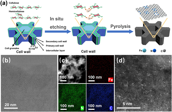
Fig. 1a illustrates the fabrication schematic of SA-FeN4/PC for straightforward preparation. Initially, Fe3+ ions are immobilized onto the lignocellulose by chelation with the oxygen-containing groups on the lignocellulose during the in situ etching process [30,31]. As shown in Fig. S1 (Supporting information), the crystallinity of the cellulose increased from 53.8 to 61.2 after FeCl3 pretreatment, which is attributed to the interaction between Fe and the cellulose in the amorphous region, as well as with hemicellulose [30,32]. Chloride ions (Cl−) weaken the β-(1,4)-glycosidic and β-O-4 bonds in lignocellulose, thereby removing portions of cellulose, hemicellulose, and lignin, which results in the formation of abundant nanopores on the wood cell wall [26,33,34]. As shown in Fig. S2 (Supporting information), the methoxy functional group of lignin at 1249 cm−1 and the vibrational peaks of the aryl ring at 1596 and 1420 cm−1 indicate the partial hydrolysis of lignin following ferric chloride pretreatment [35,36]. The resulting material is then washed several times with deionized water through centrifugation to remove excess Fe3+. The wood powder chelated with Fe3+ is subsequently ground with urea and calcined to obtain catalysts with monodispersed Fe3+ sites.
Figure 1
Figure 1.
(a) Schematic illustration of the synthesis of SA-MN4/PC. (b) TEM image of SA-FeN4/PC. (c) HAADF-STEM image and the corresponding elemental mappings of SA-FeN4/PC. (d) SA-FeN4/PC with the bright points representing Fe atoms.
The scanning electron microscopy (SEM) images of SA-FeN4/PC (Fig. S3 in Supporting information) revealed abundant micro- and mesopores in the carbon skeleton, which facilitated the interaction between the active sites and the electrolyte, thereby enhancing electrocatalytic performance. Transmission electron microscopy (TEM) images of SA-FeN4/PC showed no evidence of metallic iron particles, confirming that the iron atoms were atomically dispersed on the wood-based carbon support (Fig. 1b). Elemental mapping further demonstrated the successful incorporation of Fe and N into the carbon framework (Fig. 1c). Aberration-corrected high-angle annular dark-field scanning TEM (AC HAADF-STEM) images of SA-FeN4/PC provide clear confirmation that the Fe atoms were atomically dispersed on the wood-based carbon support (Fig. 1d). Homogeneously dispersed single-metal Fe sites were visible, with distinct intensity profiles indicating their uniform distribution [37,38]. The actual Fe content in the SA-FeN4/PC sample, determined by inductively coupled plasma atomic emission spectroscopy (ICP-AES), was found to be 2.08%. These results strongly support the notion that the hydroxy-oxygen chelation of Fe atoms with lignocellulose is effectively anchored and captured by nitrogen-doped carbon during the subsequent carbonization process.
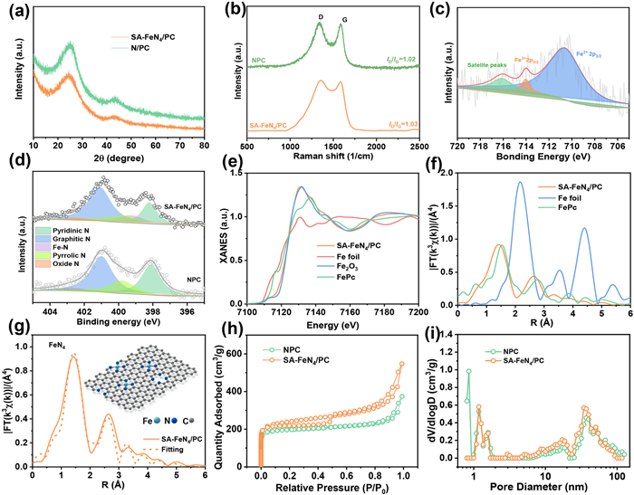
X-ray diffraction (XRD), X-ray photoelectron spectroscopy (XPS), and synchrotron hard X-ray absorption near-edge structure (XANES) were employed to investigate the material’s valence state and coordination environment. As shown in Fig. 2a, the XRD patterns of both SA-FeN4/PC and NPC samples displayed typical broad graphite peaks around 25° (002) and 44° (101) [39]. No metallic iron peaks were observed after the incorporation of Fe, suggesting that Fe may be atomically dispersed within the carbon matrix. The intensity ratio of the D band to the G band (ID/IG) for NPC and SA-FeN4/PC was 1.02 and 1.03, respectively, indicating that the introduction of Fe single atoms had a negligible effect on the overall graphitization degree of the carbon substrate. Both samples exhibited highly similar long-range ordered structures [40,41]. However, a closer examination of the Raman spectra revealed subtle differences in peak shape and peak width, despite the similar positions and intensities of the D and G bands. These differences reflect slight variations in the local microstructure or electronic properties, which can be attributed to the local perturbation of the surrounding carbon/nitrogen atomic environment by the SA-FeN4 sites [42].
Figure 2
Figure 2.
(a) XRD spectra and (b) Raman spectra of SA-FeN4/PC and NPC. (c) Fe 2p3/2 XPS spectra of SA-FeN4/PC. (d) N 1s XPS spectra of SA-FeN4/PC and NPC. (e) Fe K-edge XANES spectra of SA-FeN4/PC and reference samples. (f) Fourier-transformed (FT) k3-weighted χ(k) function of the EXAFS spectra for the Fe K-edge. (g) EXAFS fitting curves of SA-FeN4/PC (the inserted image shows the coordination environment of the proposed M-N4 (M = Fe, Ni, Co, and Cu). (h) BET N2 adsorption/desorption isotherms, and (i) corresponding pore size distributions of SA-FeN4/PC and NPC.
In the high-resolution XPS spectrum of Fe (Fig. 2c), a characteristic peak at 710.6 eV (Fe 2p3/2) corresponded to Fe3+, while a peak at 714.0 eV (Fe 2p3/2) corresponded to Fe2+, and a satellite peak at 715.6 eV further supported the successful incorporation of Fe into the structure [42,43]. The high-resolution N 1s XPS spectrum of SA-FeN4/PC (Fig. 2d) revealed five distinct peaks at 402.7, 401.1, 399.8, 399.3, and 398.1 eV, which were attributed to oxide N, graphitic N, pyrrolic N, Fe—N, and pyridinic N, respectively [42,44–46]. Although the nitrogen content in SA-FeN4/PC is slightly lower than in NPC, this reduction may be due to the chelation of Fe3+ with the oxygen-containing functional groups of glucose and xylose in the cellulose/hemicellulose hydrolysates. This interaction likely influences the nitrogen and carbon coordination environment during the high-temperature carbonization process (Table S1 in Supporting information).
The Fe K-edge XANES spectrum indicated that the valence state of Fe in SA-FeN4/PC is close to Fe3+ (Fig. 2e). The wavelet-transformed plot of SA-FeN4/PC showed an intensity maximum around 4.1 Å, similar to that of FePc, suggesting the presence of a comparable Fe—N first-shell coordination (Fig. S4 in Supporting information) [47,48]. The coordination environment of the Fe atoms was further confirmed by extended X-ray absorption fine structure (EXAFS) analysis (Fig. 2f). In the EXAFS spectrum, a strong peak at approximately 1.5 Å was attributed to Fe—N bonding, and there was an almost complete absence of Fe—Fe bonding at 2.47 Å, indicating that Fe is predominantly atomically dispersed in SA-FeN4/PC, with Fe atoms mainly coordinated to N [49]. Fitting the EXAFS data (FT-EXAFS) revealed that each Fe atom was coordinated to an average of 3.8 N atoms, with an average Fe—N bond length of 2.01 Å (Fig. 2g, Fig. S5 and Table S2 in Supporting information).
As shown in Fig. 2h, the N2 adsorption-desorption isotherms of both NPC and SA-FeN4/PC displayed type Ⅰ/Ⅳ isotherm characteristics, indicative of micro/mesoporous materials [50]. Compared to NPC (610.5 m2/g), SA-FeN4/PC exhibited a larger Brunauer-Emmett-Teller (BET) specific surface area of 752.2 m2/g, which was primarily due to the interaction between lignocellulose and ferric chloride. The pore size distribution of the materials was calculated using density functional theory (DFT) (Fig. 2i). Both NPC and SA-FeN4/PC samples exhibited porous structures, with micropores centered around 1.2 nm and mesopores centered around 40 nm. Despite the formation of FeN4 and the partial hydrolysis of lignocellulose, the microporous surface area (Smicro) for both NPC and SA-FeN4/PC remained the same at 484.2 m2/g, which was consistent with similar nitrogen uptake at p/p0 < 0.1. However, the mesoporous surface area (Smeso) of SA-FeN4/PC (268.0 m2/g) was significantly higher than that of NPC (126.3 m2/g), likely due to the in-situ etching of lignocellulose by ferric chloride. These results demonstrated that in situ etching not only enables the preparation of wood-based single-atom catalysts but also facilitates the construction of a more enriched micro/mesoporous structure in wood-based single-atom catalysts.
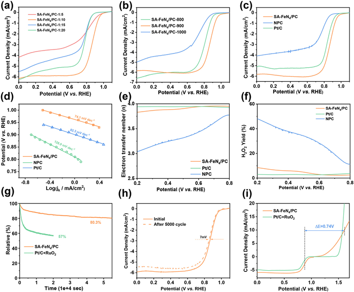
The ORR and OER activities of the catalyst were evaluated using a rotating ring disk electrode (RRDE). As shown in Fig. 3a, the sample with a nitrogen-to-wood powder ratio of 10:1 demonstrated superior ORR activity. Under these conditions, the carbonization temperature was further optimized, and SA-FeN4/PC-900, carbonized at 900 ℃, exhibited the optimal ORR performance (Fig. 3b). Among SA-FeN4/PC, NPC, and 20% Pt/C catalysts, SA-FeN4/PC displayed the highest ORR activity, with a half-wave potential (E1/2) of 0.87 V vs. RHE (Fig. 3c and Fig. S6 in Supporting information) and the lowest Tafel slope of 74.1 mV/dec (Fig. 3d). The electron transfer number was found to be greater than 3.8 (Fig. 3e), and the hydrogen peroxide yield was below 10% (Fig. 3f), indicating a four-electron ORR process. The catalyst’s durability was assessed using the constant potential method (Fig. 3g). The SA-FeN4/PC catalyst retained 80.3% of its initial current density at 0.564 V after 55,000 s. Accelerated stability tests also demonstrated the excellent stability and carbon resistance of the SA-FeN4/PC catalyst, with a minimal loss of 7 mV in E1/2 after 5000 potential cycles between 0.6 V and 1.0 V in an oxygen-saturated 0.1 mol/L KOH solution (Fig. 3h).
Figure 3
Figure 3.
(a) ORR LSV of SA-FeN4/PC-X (X = 1:5, 1:10, 1:15, 1:20) in O2-saturated 0.1 mol/L KOH at 1600 rpm. (b) ORR LSV of SA-FeN4/PC-T (T = 800, 900, 1000 ℃) in O2-saturated 0.1 mol/L KOH at 1600 rpm. (c) ORR LSV of SA-FeN4/PC vs. NPC vs. 20% Pt/C in O2-saturated 0.1 mol/L KOH at 1600 rpm. (d) Tafel plots of SA-FeN4/PC vs. NPC vs. Pt/C. Electron transfer number (e) and H2O2 yields (f) of SA-FeN4/PC, NPC, and Pt/C. (g) I-t chronoamperometry responses of SA-FeN4/PC and Pt/C in O2-saturated 0.1 mol/L KOH. (h) ORR stability of SA-FeN4/PC pre/post 5000 cycles (0.6–1.0 V). (i) Bifunctional polarization of SA-FeN4/PC vs. RuO2 (ORR/OER).
The OER performance of the catalysts was evaluated in nitrogen-saturated 0.1 mol/L KOH. As shown in the OER LSV curves in Fig. 3i, SA-FeN4/PC (with an overpotential of 380 mV) exhibited OER activity comparable to that of RuO2 (overpotential of 340 mV) at 10 mA/cm2. The overall ORR/OER performance of SA-FeN4/PC was assessed by calculating the potential difference (ΔE) between Ej=10 for OER and E1/2 for ORR (ΔE = Ej=10 − E1/2). SA-FeN4/PC exhibited a ΔE value of 0.74 V, which is comparable to that of Pt/C for ORR (E1/2) and RuO2 for OER (Ej=10) (ΔE = 0.73 V). This ΔE value is similar to that of other recently reported iron- or cobalt-based M-N-C catalysts (Table S4 in Supporting information). The outstanding ORR/OER performance of SA-FeN4/PC can be attributed to the highly active FeN4 sites and the efficient mass transfer facilitated by the three-dimensional porous structure. To clarify the role of the three-dimensional pore channels in enhancing mass transfer, we compared the electrochemical impedance spectroscopy (EIS, Fig. S7 in Supporting information) and electrochemical active surface area (ECSA, Fig. S8) of NPC and SA-FeN4/PC. The EIS fitting results show that the charge transfer resistance (Rct) of NPC is significantly higher than that of SA-FeN4/PC, directly confirming that the latter’s well-developed hierarchical pore structure effectively reduces mass transfer resistance, promoting the rapid transport of substances (O2/OH−) to the active sites. Further ECSA evaluation indicates that SA-FeN4/PC, benefiting from its rich micro/mesopore structure, exhibits a significantly higher double-layer capacitance (Cdl), meaning more effective active sites are exposed. Together with the high limiting current density exhibited by SA-FeN4/PC, these results collectively validate the critical role of its hierarchical pore structure: Maximizing the number of active sites while ensuring efficient transport of substances to these sites. These results suggest that SA-FeN4/PC is one of the most promising bifunctional oxygen electrocatalysts, with significant potential for application in rechargeable ZABs.
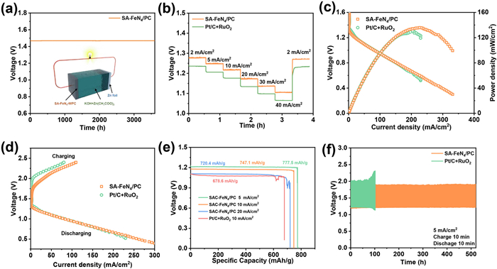
SA-FeN4/PC catalysts were used as cathodes to assemble rechargeable ZABs to evaluate their energy storage capacity. Pt/C + RuO2 was tested as a reference cathode catalyst (with equal mass ratio) for comparison. The open-circuit potential of the SA-FeN4/PC-based ZAB reached 1.47 V (Fig. 4a). During galvanostatic discharge tests at current densities ranging from 2 mA/cm2 to 40 mA/cm2, the voltage drop in ZABs assembled with SA-FeN4/PC catalysts was only 170 mV, indicating excellent discharge performance (Fig. 4b). The discharge voltage was higher than that of Pt/C + RuO2, highlighting the superior ORR performance of the SA-FeN4/PC catalysts. Furthermore, the discharge voltage was found to reversibly recover when the current density was reduced back to 2 mA/cm2, indicating excellent rate capability. The ZABs assembled with SA-FeN4/PC catalysts demonstrated high capacity and remarkable rate performance. Notably, the SA-FeN4/PC-based ZAB achieved a power density of 135 mW/cm2, which is higher than that of the Pt/C + RuO2-based ZAB (127 mW/cm2) (Fig. 4c). Additionally, the SA-FeN4/PC-based battery exhibited a small voltage gap between charging and discharging, demonstrating good charging and discharging efficiency (Fig. 4d). At a discharge current density of 5 mA/cm2, the battery delivered a specific capacity of 777.5 mAh/gZn, corresponding to 95% of the theoretical capacity (~820 mAh/gZn) (Fig. 4e). Even when the current density was increased to 10 mA/cm2 and 20 mA/cm2, the capacity only decreased by 30.4 mAh/gZn and 57.1 mAh/gZn, respectively, compared to the capacity at 5 mA/cm2. The durability of the ZABs was further investigated through long-term galvanostatic charge/discharge tests at 5 mA/cm2 (Fig. 4f). The voltage gap of the Pt/C + RuO2-based ZAB increased significantly with cycling, whereas the voltage change in the SA-FeN4/PC-based ZAB was minimal, indicating better stability of the SA-FeN4/PC catalyst during both the ORR and OER processes. To evaluate the practical applicability of the assembled ZABs, two SA-FeN4/PC-based batteries were connected in series to successfully power a light-emitting diode (LED) with an output of approximately 3 V (Fig. S9 in Supporting information). This serves as an intuitive and compelling demonstration of the battery’s practical power supply capabilities, validating its potential as a reliable energy device. It further highlights the excellent practical applicability of the SA-FeN4/PC catalyst, which was prepared using the in situ etching method.
Figure 4
Figure 4.
(a) OCV plots of ZABs. (b) Galvanostatic discharge curves at current densities ranging from 2 mA/cm2 to 40 mA/cm2. (c) Discharge polarization curves and corresponding power density plots of ZAB using the SA-FeN4/PC and Pt/C-RuO2 couple as air electrodes, respectively. (d) Charge and discharge polarization curves of the SA-FeN4/PC and Pt/C + RuO2 air electrodes for the rechargeable ZABs. (e) Galvanostatic discharge curves of the ZABs with the SA-FeN4/PC at 5, 10, and 20 mA/cm2 and Pt/C + RuO2 at 10 mA/cm2. (i) Discharge/charge cycling curves of ZAB using the SA-FeN4/PC and Pt/C-RuO2 couple as air electrodes at 5 mA/cm2.
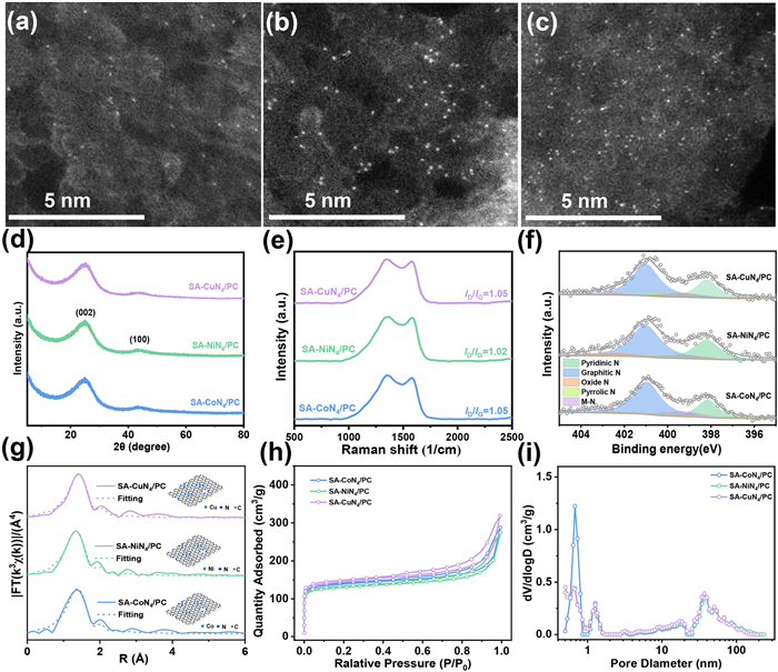
Interestingly, the in-situ etching method used to prepare single-atom catalysts could be easily extended to other metals, such as Co, Ni, and Cu. The physicochemical properties of the catalysts were thoroughly investigated using various characterization techniques, including XRD, Raman spectroscopy, XPS, HAADF-STEM, XANES, and BET. Single-atom M-N4/PC (M = Co, Ni, and Cu) catalysts were prepared by using different metal salt precursors. TEM, HAADF-STEM, and corresponding EDS elemental mapping revealed that the metal element (M = Ni, Co, Cu) and nitrogen were uniformly distributed within the carbon framework, with no evidence of metal particle agglomeration. The aberration-corrected HAADF-STEM images clearly showed isolated bright dots in SA-CoN4/PC (Fig. 5a), SA-NiN4/PC (Fig. 5b), and SA-CuN4/PC (Fig. 5c), confirming the atomic dispersion of Co, Ni, and Cu atoms anchored on the nitrogen-doped carbon structure. XRD analysis revealed no characteristic peaks corresponding to metal crystals, further supporting the atomic dispersion of the metal species (Fig. 5d). Raman spectra (Fig. 5e) indicated the presence of carbon defects in all samples. Furthermore, the high-resolution XPS N 1s spectra (Fig. 5f) showed the M-N (M = Co, Ni, Cu) bonding peak at 399.3 eV, confirming the successful incorporation of metal-nitrogen coordination. The prepared SA-NiN4/PC, SA-CoN4/PC, and SA-CuN4/PC catalysts also exhibited typical MN4 (M = Co, Ni, Cu) structures, as demonstrated in Fig. 5g, Figs. S10 and S11, and Table S2 (Supporting information). Additionally, as shown in Fig. 5h and i and Table S3 (Supporting information), the SA-MN4/PC catalysts (M = Co, Ni, Cu) displayed larger specific surface areas and a high abundance of micro/mesopores. These results highlight the advantages of the in-situ etching strategy. During the high-temperature carbonization process, transition metal ions (Fe, Co, Ni, and Cu) chelated with the oxygen-containing functional groups of lignocellulosic hydrolysis products, effectively immobilizing the metal ions and forming the MN4 ligand structures (M = Co, Ni, Cu).
Figure 5
Figure 5.
AC HAADF-STEM images of (a) SA-CoN4/PC, (b) SA-NiN4/PC, and (c) SA-CuN4/PC with the bright points representing M (M = Co, Ni, and Cu) atoms. (d) XRD spectra, (e) Raman spectra, (f) N 1s XPS spectra, (g) EXAFS fitting curves (the inserted image shows the coordination environment of the proposed M-N4 (M = Ni, Co, and Cu), (h) BET N2 adsorption/desorption isotherms, and corresponding pore size distributions (i) of SA-CoN4/PC, SA-NiN4/PC, and SA-CuN4/PC.
To clarify the intrinsic influence of metal centers on ORR/OER performance, we systematically evaluated the electrocatalytic activity of SA-MN4/PC (M = Fe, Co, Ni, Cu) catalysts (Fig. S12 in Supporting information). In 0.1 mol/L KOH, the ORR activity (E1/2) follows the order: Fe > Co > Cu > Ni, with SA-FeN4/PC exhibiting the most positive E1/2, significantly outperforming SA-CoN4/PC, SA-CuN4/PC, and the least active SA-NiN4/PC. In contrast, the OER activity (overpotential at 10 mA/cm2, η) shows the trend: Fe < Co < Ni < Cu, with SA-FeN4/PC having the lowest overpotential (highest activity) and SA-CuN4/PC exhibiting the highest overpotential (lowest activity). These contrasting activity trends confirm that the selection of metal centers is a key factor in tuning the ORR and OER performance in single-atom catalysts.
In conclusion, we demonstrated an in-situ etching-calcination method, without the need for pickling, to anchor atomically dispersed transition metals (Fe, Co, Ni, and Cu) onto wood-based porous nitrogen-doped carbon for use as cathode catalysts in ZABs. Transition metal chlorides effectively generated a large number of microchannels in the cell walls by hydrolyzing lignocellulose. Subsequently, transition metal ions were uniformly dispersed on the wood-based nitrogen-doped carbon framework, forming MN4 (M = Fe, Co, Ni, and Cu) structures. Benefiting from these structural advantages, the prepared SA-FeN4/PC catalyst exhibited excellent ORR/OER activity and stability. Furthermore, when assembled into aqueous ZABs, the catalyst demonstrated outstanding rechargeability and long-term cycle stability, maintaining performance over 520 h. This work provided a novel approach for the large-scale preparation of single-atom catalysts as electrode materials for rechargeable ZABs.
The authors declare that they have no known competing financial interests or personal relationships that could have appeared to influence the work reported in this paper.
Acknowledgments
We are grateful for the financial support by National Key Research and Development Program (No. 2023YFE0109600), National Natural Science Foundation of China (Nos. 32401519, 32471811, and 32201499), Hainan Key Laboratory of Storage & Processing of Fruits and Vegetables (No. HNGS202102), Guangzhou Key Research and Development Program (No. 2023B03J1330), State Key Laboratory of Pulp and Paper Engineering (No. 2024C04), Guangzhou Basic and Applied Basic Research Foundation (Nos. 2024A04J3413 and 2024A04J3704), and Guangdong Basic and Applied Basic Research Foundation (Nos. 2025A1515011107, 2024A1515011229, and 2023B1515040013).
Supplementary materials
Supplementary material associated with this article can be found, in the online version, at doi:10.1016/j.cclet.2025.111873.
Z. Zhang, X. Gao, M. Dou, et al., J. Mater. Chem. A 5 (2017) 1526–1532. doi: 10.1039/C6TA09124E
Figure 1
(a) Schematic illustration of the synthesis of SA-MN4/PC. (b) TEM image of SA-FeN4/PC. (c) HAADF-STEM image and the corresponding elemental mappings of SA-FeN4/PC. (d) SA-FeN4/PC with the bright points representing Fe atoms.
Figure 2
(a) XRD spectra and (b) Raman spectra of SA-FeN4/PC and NPC. (c) Fe 2p3/2 XPS spectra of SA-FeN4/PC. (d) N 1s XPS spectra of SA-FeN4/PC and NPC. (e) Fe K-edge XANES spectra of SA-FeN4/PC and reference samples. (f) Fourier-transformed (FT) k3-weighted χ(k) function of the EXAFS spectra for the Fe K-edge. (g) EXAFS fitting curves of SA-FeN4/PC (the inserted image shows the coordination environment of the proposed M-N4 (M = Fe, Ni, Co, and Cu). (h) BET N2 adsorption/desorption isotherms, and (i) corresponding pore size distributions of SA-FeN4/PC and NPC.
Figure 3
(a) ORR LSV of SA-FeN4/PC-X (X = 1:5, 1:10, 1:15, 1:20) in O2-saturated 0.1 mol/L KOH at 1600 rpm. (b) ORR LSV of SA-FeN4/PC-T (T = 800, 900, 1000 ℃) in O2-saturated 0.1 mol/L KOH at 1600 rpm. (c) ORR LSV of SA-FeN4/PC vs. NPC vs. 20% Pt/C in O2-saturated 0.1 mol/L KOH at 1600 rpm. (d) Tafel plots of SA-FeN4/PC vs. NPC vs. Pt/C. Electron transfer number (e) and H2O2 yields (f) of SA-FeN4/PC, NPC, and Pt/C. (g) I-t chronoamperometry responses of SA-FeN4/PC and Pt/C in O2-saturated 0.1 mol/L KOH. (h) ORR stability of SA-FeN4/PC pre/post 5000 cycles (0.6–1.0 V). (i) Bifunctional polarization of SA-FeN4/PC vs. RuO2 (ORR/OER).
Figure 4
(a) OCV plots of ZABs. (b) Galvanostatic discharge curves at current densities ranging from 2 mA/cm2 to 40 mA/cm2. (c) Discharge polarization curves and corresponding power density plots of ZAB using the SA-FeN4/PC and Pt/C-RuO2 couple as air electrodes, respectively. (d) Charge and discharge polarization curves of the SA-FeN4/PC and Pt/C + RuO2 air electrodes for the rechargeable ZABs. (e) Galvanostatic discharge curves of the ZABs with the SA-FeN4/PC at 5, 10, and 20 mA/cm2 and Pt/C + RuO2 at 10 mA/cm2. (i) Discharge/charge cycling curves of ZAB using the SA-FeN4/PC and Pt/C-RuO2 couple as air electrodes at 5 mA/cm2.
Figure 5
AC HAADF-STEM images of (a) SA-CoN4/PC, (b) SA-NiN4/PC, and (c) SA-CuN4/PC with the bright points representing M (M = Co, Ni, and Cu) atoms. (d) XRD spectra, (e) Raman spectra, (f) N 1s XPS spectra, (g) EXAFS fitting curves (the inserted image shows the coordination environment of the proposed M-N4 (M = Ni, Co, and Cu), (h) BET N2 adsorption/desorption isotherms, and corresponding pore size distributions (i) of SA-CoN4/PC, SA-NiN4/PC, and SA-CuN4/PC.


 DownLoad:

 下载:


 下载:

