Lithiated sulfonated covalent organic frameworks as active fillers in solid polymer electrolytes for room-temperature all-solid-state lithium batteries
Citation:
Chunna Cui, Liang He, Xingtong Guo, Pengfei Wu, Jitao Huang, Tao Wei. Lithiated sulfonated covalent organic frameworks as active fillers in solid polymer electrolytes for room-temperature all-solid-state lithium batteries[J]. Chinese Chemical Letters,
2026, 37(12): 111871.
doi:
10.1016/j.cclet.2025.111871
Lithiated sulfonated covalent organic frameworks as active fillers in solid polymer electrolytes for room-temperature all-solid-state lithium batteries
English
Lithiated sulfonated covalent organic frameworks as active fillers in solid polymer electrolytes for room-temperature all-solid-state lithium batteries
College of New Energy and Materials, Ningde Normal University, Ningde 352100, China
b.
School of Energy and Power, Jiangsu University of Science and Technology, Zhenjiang 212003, China
c.
National Key Laboratory for Development and Utilization of Forest Food Resources, Co-Innovation Center for Sustainable Forestry in Southern China, Nanjing Forestry University, Nanjing 210037, China
d.
Fujian Provincial Key Laboratory of Featured Biochemical and Chemical Materials, Ningde Normal University, Ningde 352100, China
wt863@126.com (T. Wei). 1 These authors contributed equally to this work.
Received Date:
26 July 2025 Accepted Date:
21 September 2025 Revised Date:
10 September 2025 Available Online:
15 December 2026
Abstract:
In this study, sulfonic acid group was incorporated into the covalent organic framework (COF) to synthesize TpPa-SO3H, which was subsequently lithiated to obtain TpPa-SO3Li. And then a solid composite electrolyte (SCE), integrating PVDF-HFP, TpPa-SO3Li, and LiTFSI was prepared. The SCE exhibited a high lithium-ion transference number (0.72), as well as a high ionic conductivity at 30 °C (2.15 × 10⁻⁴ S/cm). Electrochemical tests revealed that the Li symmetric cell achieved remarkable cycling stability, sustaining operation for > 500 h at 60 °C (0.2 mA/cm2) and > 1000 h at room temperature (0.1 mA/cm2). The assembled LFP//Li battery exhibited a stable discharge capacity of 129.33 mAh/g after 110 cycles at 0.2 C under room temperature. This COF-based composite electrolyte significantly enhances lithium-ion conduction and interfacial stability, offering a novel material choice and design strategy for advancing next-generation solid-state lithium-ion batteries.
The development of next-generation energy storage systems focuses on increasing energy density, improving safety performance, and extending lifespan, traditional lithium-ion batteries with liquid electrolyte face critical safety risks, including leakage and thermal runaway, which significantly limit their further applications [1-4]. Solid polymer electrolytes (SPEs) are typically constructed using a crosslinked polymer matrix impregnated with lithium bis(trifluoromethanesulfonyl)imide (LiTFSI) salts, offering low volatility and excellent flexibility, which enables good contact with lithium metal anodes and significantly reduces interfacial resistance between the electrodes for the reason of “solid-solid contact” [5-8]. Thus, the SPEs have attracted much attentions and are thought to be the ideal candidate for solving the safety problems of conventional batteries for their excellent electrochemical performance, mechanical stabilities, and solid-state properties [9-12]. Especially in all-solid-state lithium metal batteries (ASSLMBs), the lithium metal anode provides unparalleled benefits for increasing battery energy density, owing to its exceptional theoretical specific capacity (3860 mAh/g) [13-17].
However, SPEs still face several challenges, including low ionic conductivity at room temperature, poor mechanical strength, and interfacial instability with high-voltage cathodes [18-21]. To address these shortcomings, researchers have introduced active fillers (e.g., inorganic nanoparticles, oxides, or functionalized materials) into the polymer matrix to improve ion transport properties, enhance mechanical strength, and stabilize the electrode-electrolyte interface [22-25]. Nevertheless, conventional active fillers often suffer from poor dispersion and structural inhomogeneity, which limits their potential for further performance enhancement [26-29].
Against this background, covalent organic frameworks (COFs), characterized by their well-defined porous structures, have garnered significant interest as promising filler materials [30-32]. The unique ordered porous architecture of COF materials can provide continuous ion transport channels, facilitating the migration of lithium ions [33-36]. Furthermore, polar functional groups (such as sulfonate and carbonyl groups) can be incorporated into the COF framework, serving as lithium-ion conduction sites to further reduce the migration energy barrier and enhance ionic conductivity [37,38]. In addition, the excellent chemical and thermal stability of COF materials allows them to exhibit superior stability in electrochemical environments, improving interfacial compatibility between solid electrolytes and electrodes to mitigate lithium dendrite propagation [39]. Ko et al. [40] incorporated the COF (tetrakis(4-carboxyphenyl)porphyrin, TCPP) into PEO. TCPP effectively suppressed the crystallinity of PEO, the system demonstrated an ionic conductivity of 2.21 × 10⁻⁴ S/cm when tested at 65 ℃, coupled with a lithium-ion transference number (tLi+) of 0.23 at 25 ℃. Furthermore, Ma et al. [41] introduced COF-LZU1 into PEO, which effectively inhibited the growth of lithium dendrites, achieving a tLi+ of 0.43. Additionally, the system demonstrated stable cycling for 350 h at 60 ℃ under a current density of 0.1 mA/cm2.
Therefore, in this study, sulfonic acid group was incorporated into the COF to synthesize TpPa-SO3H, which was subsequently lithiated into TpPa-SO3Li using a lithium nitrate solution. TpPa-SO3Li was then incorporated as an active filler into PVDF-HFP, this electrolyte displays both a significant ionic conductivity (2.15 × 10⁻⁴ S/cm, 30 ℃) and an outstanding tLi+ (0.72). Firstly, as a COF material, the TpPa-SO3Li material exhibits an ordered porous architecture and elevated surface area, which collectively promote the formation of continuous Li+ transport channels, leading to improved ionic conductivity. Secondly, the high Lewis basicity and stability of the SO3– groups contribute to enhanced lithium-ion conductivity. Finally, the substitution of H+ with Li+ in TpPa-SO3Li generates uniformly distributed lithium-ion conduction sites. As a result, the symmetric Li/SCE/Li cell demonstrated remarkable cycling durability ( > 500 h) at 60 ℃, sustaining a small polarization voltage of approximately 20 mV when cycled at 0.2 mA/cm2. It also achieved stable cycling for over 1000 h at room temperature under 0.1 mA/cm2, maintaining a polarization voltage of around 100 mV. These results highlight the material's excellent electrochemical performance.
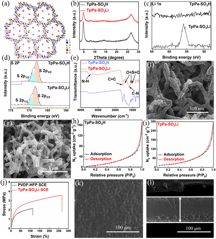
The lithium-sulfonated covalent organic framework (TpPa-SO3Li) is constructed through an irreversible keto-enamine linkage, formed by the polycondensation of Tp and Pa-SO3H followed by lithiation. As illustrated in Fig. 1a, this framework exhibits a crystalline two-dimensional architecture with hexagonal (hcb) symmetry, generating an ordered honeycomb network featuring periodically arranged micropores of approximately 11.8 Å in diameter. The XRD patterns of TpPa-SO3H and TpPa-SO3Li are shown in Fig. 1b, characteristic diffraction peaks were observed at 4.6° and 26.2°, corresponding to the (100) and (001) lattice planes, respectively. This suggests that the lithium doping process preserves the overall structural integrity. However, compared to TpPa-SO3H, the intensity of the peaks for TpPa-SO3Li is reduced, implying that the lithium doping process reduces the crystallinity. To further confirm lithium incorporation, XPS analysis was conducted on the COF powder before and after lithiation (Figs. 1c and d). The Li 1s spectrum of TpPa-SO3Li exhibited a distinct peak at approximately 55.9 eV, which was absent in TpPa-SO3H, verifying the successful incorporation of lithium. The full XPS spectra of TpPa-SO3H and TpPa-SO3Li further support this conclusion (Fig. S1 in Supporting information). Additionally, the S 2p spectrum of TpPa-SO3Li exhibited a shift toward higher binding energy relative to TpPa-SO3H, suggesting an altered sulfur chemical environment. This shift suggests that lithium successfully substituted hydrogen within the sulfonate groups [42]. In addition to the chemical environment changes revealed by XPS analysis, Fourier transform infrared spectroscopy (FTIR) data further corroborated the aforementioned structural transformation from the perspective of functional group vibration characteristics (Fig. 1e). TpPa-SO3Li exhibits stretching vibration peaks at 1230 cm-1 (C–N), 1572 cm-1 (C=C), and 3380 cm-1 (N–H), which indicate the presence of keto-enamine linkages. Meanwhile, the peaks at 1026, 1085, and 1438 cm−1 are attributed to the O=S=O stretching vibrations of the sulfonate group [43]. Figs. 1f and g present SEM images of TpPa-SO3Li at different magnifications, which consists of bar-shaped particles aggregated together. This morphology results in a significantly increased specific surface area, which is beneficial for enhancing ion conductivity, thereby optimizing the battery's overall electrochemical performance. Subsequently, N2 adsorption/desorption tests were conducted on TpPa-SO3Li and TpPa-SO3H (Figs. 1h and i), which revealed typical Type Ⅳ N2 adsorption/desorption isotherms. Notably, the specific surface area of TpPa-SO3Li is significantly higher than that of TpPa-SO3H (Table S1 in Supporting information), indicating an increase in specific surface area after lithiation. Fig. S2 (Supporting information) show the EDS images of C, O, S, and N elements in TpPa-SO3Li, with the presence of sulfur (S) confirming the successful incorporation of sulfonate (-SO3Li) groups. Energy-dispersive X-ray spectroscopy (EDX) was employed to confirm the presence of sulfur (Fig. S3 in Supporting information), while Table S2 provides a detailed quantification of the sulfur content.
Figure 1
Figure 1.
(a) The topological structure of TpPa-SO3Li. (b) XRD curves of COF (TpPa-SO3H and TpPa-SO3Li). XPS spectra of different elements in TpPa-SO3H and TpPa-SO3Li: (c) S 2p, (d) Li 1s. (e) FTIR spectra of TpPa-SO3H and TpPa-SO3Li powders. (f, g) SEM images of TpPa-SO3Li at different magnifications. BET nitrogen adsorption-desorption curves of (h) TpPa-SO3H and (i) TpPa-SO3Li. (j) Stress−strain curves of PVDF-HFP SCE and TpPa-SO3Li SCE. TpPa-SO3Li SCE (k) surface and (l) cross-section SEM.
Fig. S4 (Supporting information) demonstrates the mechanical flexibility of the TpPa-SO3Li SCE membrane, while also clearly revealing the uniformity of its surface. Stress-strain tests were conducted on the synthesized SCEs (Fig. 1j). It can be observed that after the incorporation of TpPa-SO3Li, both the tensile strength and elongation at break of the membrane showed a significant improvement, increasing from 2.17 MPa and 113.57% (for the SCE without TpPa-SO3Li) to 3.59 MPa and 266.61% (for the T TpPa-SO3Li -incorporated SCE), respectively. SEM images displaying both the surface morphology and cross-sectional structure of the membrane are presented in Figs. 1k and l. The surface is relatively smooth, where TpPa-SO3Li is uniformly distributed, and the membrane thickness is approximately 82 μm.
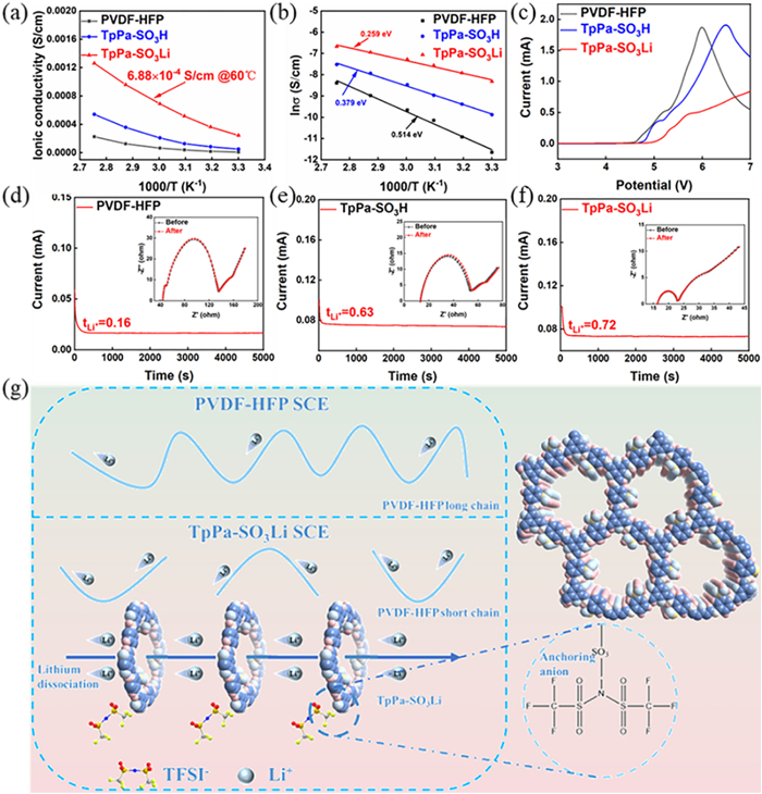
Ionic conductivity is a critical parameter for assessing the performance of solid-state electrolytes. Fig. S5 (Supporting information) presents the EIS results of symmetric SS||SS cells. The disappearance of the semicircular arc after incorporating TpPa-SO3Li suggests a reduced interfacial impedance and enhanced interfacial compatibility. Furthermore, among the tested SCEs, TpPa-SO3Li SCE exhibited the lowest impedance at all temperatures, achieving a remarkable ionic conductivity of 6.88 × 10⁻⁴ S/cm at 60 ℃. This value is significantly higher than that of TpPa-SO3H SCE and PVDF-HFP SCE, highlighting its superior lithium-ion transport properties (Fig. 2a). Additionally, the TpPa-SO3Li SCE maintains a high ionic conductivity of 2.15 × 10⁻⁴ S/cm at 30 ℃, surpassing that of solid electrolytes doped with TiO2 (9.9 × 10⁻⁵ S/cm) [44] and that of LLZO-based solid electrolytes (1.2 × 10⁻⁵ S/cm) [45]. The high ionic conductivity may be attributed to the following reasons: Firstly, as a COF material, TpPa-SO3Li features a well-ordered porous structure and high specific surface area, both of which facilitate continuous lithium-ion conduction pathways, thereby enhancing ionic conductivity [46]. Second, the high Lewis basicity and stability of the SO3- groups contribute to enhanced lithium-ion conductivity [47]. Finally, the substitution of H+ with Li+ in TpPa-SO3Li generates uniformly distributed lithium-ion conduction sites [48].
Figure 2
Figure 2.
(a) Ionic conductivity curves for different SCEs. (b) Activation energy curves of different SCEs. (c) LSV curves of different SCEs. Ion mobility numbers of different SCEs: (d) PVDF-HFP SCE, (e) TpPa-SO3H SCE, (f) TpPa-SO3Li SCE. (g) Schematic illustration of lithium-ion transport through TpPa-SO3Li SCE and PVDF-HFP SCE.
To further investigate the superior ionic transport properties of TpPa-SO3Li, the activation energy for lithium-ion migration in different SCEs was determined. The Arrhenius plots for different SCEs are presented in Fig. 2b, revealing that TpPa-SO3Li SCE exhibits the lowest activation energy (0.259 eV), which is significantly lower than that of TpPa-SO3H SCE (0.379 eV) and PVDF-HFP SCE (0.514 eV). The lower activation energy indicates a reduced migration barrier for Li+. This is because Li+ dissociates more easily from the sulfonate groups than H+, thereby effectively reducing the overall activation energy [49]. Therefore, the introduction of TpPa-SO3Li effectively reduces the migration barrier for lithium ions.
The electrochemical stability windows of SS//Li cells assembled with different SCEs were evaluated via LSV (Fig. 2c). The electrochemical stability window of TpPa-SO3Li SCE is approximately 5.0 V, which is higher than that of TpPa-SO3H SCE and PVDF-HFP SCE. This can be attributed to the rigid framework structure of TpPa-SO3Li, which is constructed through covalent bonding of organic units [43]. The structure exhibits high rigidity and excellent pressure resistance, as a result, the structural robustness of the solid electrolyte membrane is reinforced, and its operational voltage range is expanded. A wider electrochemical stability window not only improves the safety of solid-state electrolytes in practical application but also enables the employing of cathode materials with high-voltage, thereby broadening battery design possibilities.
Subsequently, the tLi+ of Li//Li cells incorporating different SCEs was determined via steady-state polarization, as depicted in Figs. 2d-f. The lithium-ion transference numbers varied from 0.16 for PVDF-HFP SCE (the lowest) to 0.63 for TpPa-SO3H SCE, reaching a maximum of 0.72 for TpPa-SO3Li SCE. This enhancement can be attributed to several factors: First, the distinctive one-dimensional structure of TpPa-SO3Li SCE facilitates rapid lithium-ion conduction pathways [48]. Second, the alternating arrangement of sulfonate and keto groups in TpPa-SO3Li SCE promotes lithium-ion migration along oxygen atoms [50]. Finally, by acting as ion-sieving moieties, the pore-wall-anchored sulfonate groups suppress anion diffusion and reduce polarization effects, facilitating a consistent and balanced distribution of lithium ions [31]. The mechanism by which TpPa-SO3Li enhances electrochemical performance is illustrated in Fig. 2g. For the reason that in the polymer matrixes, the migration of Li+ cations mainly relies on the motion of the polymeric chains and this happens mostly in amorphous phases. The incorporation of COF additives into the polymer electrolyte significantly enhances Li-ion conductivity by suppressing the crystalline phase formation. This modification inhibits the local reorganization of polymer chains and reduces overall crystallinity, effectively fragmenting the extended polymer chains into shorter segments. What is more, TpPa-SO3Li provides a one-dimensional lithium-ion transport pathway and effectively anchors anions (TFSI-), thereby facilitating the dissociation of LiTFSI.
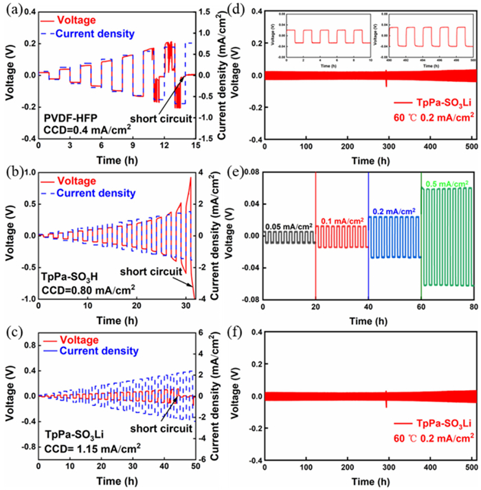
On this basis, different SCEs were integrated into Li-ion battery configurations, and their critical current densities (CCDs) were determined, with the results displayed in Figs. 3a-c. Notably, TpPa-SO3Li SCE exhibited the highest CCD value of 1.15 mA/cm2, surpassing those of PVDFD-HFP SCE and TpPa-SO3H SCE. Such performance improvement arises from the reduced internal resistance enabled by TpPa-SO3Li SCE's superior ionic transport properties, including high conductivity and Li+ transference number, thus improving its performance at high current densities. Clearly, TpPa-SO3Li SCE demonstrated the best performance, as evidenced by its charge-discharge characteristics in Li-ion batteries. It maintained stable operation for > 500 h at 60 ℃ and 0.2 mA/cm2 with a polarization voltage of approximately 20 mV (Fig. 3d). In order to assess the lithium plating/stripping stability of TpPa-SO3Li SCE at different current densities, its rate performance was evaluated and the results are shown in Fig. 3e. TpPa-SO3Li SCE maintained a low polarization voltage for lithium batteries at different current densities between 0.05 mA/cm2 and 0.5 mA/cm2. These results confirm TpPa-SO3Li SCE has excellent interfacial stability. This is further supported by the impedance measurements of the lithium battery before and after cycling (Fig. S6 in Supporting information). Compared to TpPa-SO3H SCE and PVDF-HFP SCE, TpPa-SO3Li SCE maintained a minimum impedance value before and after cycling. Owing to the high lithium-ion conductivity of TpPa-SO3Li SCE at room temperature, its symmetric Li//Li cell was tested for charge-discharge cycling under ambient conditions. The TpPa-SO3Li SCE symmetric cell exhibited stable operation for exceeding 1000 h with an applied current density of 0.1 mA/cm2, and the polarization voltage was maintained around 100 mV (Fig. 3f).
Figure 3
Figure 3.
CCD curves of SCEs at 60 ℃: (a) PVDF-HFP SCE; (b) TpPa-SO3H SCE; (c) TpPa-SO3Li SCE. (d) Long cycling curve of TpPa-SO3Li SCE at 60 ℃ at 0.2 mA/cm2. (e) Multiplicity performance curve of TpPa-SO3Li SCE at 60 ℃. (f) Long cycle curve of TpPa-SO3Li SCE at 0.1 mA/cm2 at room temperature.
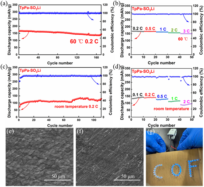
To assess the feasibility of SCEs in practical applications, a full cell was constructed with LiFePO4 serving as the cathode material, lithium metal as the anode, and various SCEs as the electrolyte separators. At 60 ℃ and 0.2 C, the long-cycle performance of TpPa-SO3Li SCE is shown in Fig. 4a. After 170 cycles, the cell exhibited a stable discharge capacity of 144.3 mAh/g with nearly ideal Coulombic efficiency (100.1%), whereas PVDF-HFP SCE and TpPa-SO3H SCE failed to operate stably (Fig. S7 in Supporting information). TpPa-SO3Li SCE showed the best performance, as further supported by its charge-discharge curves (Fig. S8 in Supporting information). After 100 cycles, it exhibited the highest discharge specific capacity and a stable polarization voltage. At 0.5 C, after 110 cycles, a stable discharge capacity of 149.65 mAh/g was retained, accompanied by a Coulombic efficiency of 97.48% (Fig. S9 in Supporting information), demonstrating excellent stability under higher current densities. Moreover, the rate capability of TpPa-SO3Li SCE was systematically assessed at different C-rates (Fig. 4b). It exhibited 168, 166, 162, 157, and 150 mAh/g at multiplicities of 0.2, 0.5, 1, 2, and 3 C, respectively, indicating its ability to sustain high-capacity retention under increasing charge-discharge rates.
Figure 4
Figure 4.
At 60 ℃, TpPa-SO3Li SCE exhibits (a) a long-cycle performance curve at 0.2 C and (b) a rate performance curve. At room temperature, TpPa-SO3Li SCE presents (c) a long-cycle performance curve at 0.2 C, (d) a rate performance curve. SEM images of the lithium metal surface after cycling with (e) PVDF-HFP and (f) TpPa-SO3Li electrolytes. (g) The optical photograph demonstrates an LED light illuminated by TpPa-SO3Li SCE at room temperature.
To further evaluate its long-term stability under ambient conditions, cycling performance tests were conducted at room temperature (Fig. 4c). At 0.2 C, the TpPa-SO3Li SCE operated stably for 110 cycles, maintaining a discharge specific capacity of 129.33 mAh/g with a high Coulombic efficiency of 99.58%. Moreover, TpPa-SO3Li SCE continued to demonstrate excellent cycling performance at different rates (Fig. 4d). It exhibited discharge specific capacities of 143, 141, 128, 115, and 95 mAh/g at 0.1, 0.2, 0.5, 1, and 2 C, respectively. These results highlight the outstanding electrochemical stability and rate performance of TpPa-SO3Li SCE, demonstrating its potential as a novel electrolyte formulation enabling enhanced performance in solid-state lithium metal battery systems.
Furthermore, cyclic voltammetry (CV) tests were performed on the full cell of TpPa-SO3Li SCE at both 60 ℃ and room temperature (Fig. S10 in Supporting information). At 60 ℃, the oxidation potential (3.59 eV) and reduction potential (3.25 eV) in the first four cycles overlapped well. At room temperature, the oxidation potential increased to 3.75 eV, while the reduction potential decreased to 3.12 eV. However, a high degree of overlap was still maintained, indicating the formation of a stable SEI membrane even at room temperature. Furthermore, Fig. S11 (Supporting information) shows the EIS results before and after 10 cycles of the full cell. The results show that the resistance of PVDF-HFP SCE increased from 374.7 Ω to 769.8 Ω and that of TpPa-SO3H SCE increased from 297.5 Ω to 650.8 Ω after 10 cycles. Alternatively, after 10 cycles, the resistance of TpPa-SO3Li SCE decreased from 241.8 Ω to 175 Ω, further indicating that the addition of TpPa-SO3Li significantly enhanced the stability of the SEI membrane. The lithium metal surface of the cycled battery was subsequently characterized via SEM (Figs. 4e and f). Compared to the lithium metal surface with PVDF-HFP SCE, the surface with TpPa-SO3Li SCE appeared significantly smoother and more uniform. This indicates that the incorporation of TpPa-SO3Li as a filler effectively improves the compatibility at the interface of the polymer electrolyte and metallic lithium. Fig. 4g illustrates that TpPa-SO3Li SCE can successfully power a “COF” LED light at room temperature.
In conclusion, TpPa-SO3H was successfully prepared in this work and TpPa-SO3Li was obtained by replacing H+ with Li+via lithium nitrate solution. TpPa-SO3Li was incorporated as an active filler into PVDF-HFP polymers, which demonstrated a high ionic conductivity of 6.88 × 10⁻⁴ S/cm at 60 ℃, and still had a high ionic conductivity at 30 ℃ of 2.15 × 10⁻⁴ S/cm ionic conductivity at 30 ℃. The assembled LFP//Li battery can maintain a discharge specific capacity of 144.3 mAh/g after 170 cycles at 60 ℃ and 0.2 C. And it can run stably for 110 cycles at room temperature 0.2 C and maintain a discharge specific capacity of 129.33 mAh/g. This strategy offers an alternative pathway for the commercialization of solid-state electrolytes.
CRediT authorship contribution statement
Chunna Cui: Writing – original draft, Investigation, Data curation, Conceptualization. Liang He: Writing – original draft, Investigation, Data curation, Conceptualization. Xingtong Guo: Investigation, Data curation, Conceptualization. Pengfei Wu: Investigation, Data curation, Conceptualization. Jitao Huang: Writing – review & editing, Methodology, Funding acquisition, Conceptualization. Tao Wei: Writing – review & editing, Supervision, Funding acquisition, Conceptualization.
Declaration of competing interest
The authors declare that they have no known competing financial interests or personal relationships that could have appeared to influence the work reported in this paper.
Acknowledgments
This work was financially supported by Natural Science Foundation of China (Nos. 21701083, 22179054), Ningde Normal University (No. 2022T10) and Key Research and Industrialization Projects for Technological Innovation of Fujian (No. 2024XQ026).
Supplementary materials
Supplementary material associated with this article can be found, in the online version, at doi:10.1016/j.cclet.2025.111871.
[1]
X. Guo, X. Jiang, R. Luo, et al., Chem. Commun. 6 (2025) 12956–12959. doi: 10.1039/d5cc02920a
K. Jeong, S. Park, G.Y. Jung, et al., J. Am. Chem. Soc. 141 (2019) 5880–5885. doi: 10.1021/jacs.9b00543
Figure 1
(a) The topological structure of TpPa-SO3Li. (b) XRD curves of COF (TpPa-SO3H and TpPa-SO3Li). XPS spectra of different elements in TpPa-SO3H and TpPa-SO3Li: (c) S 2p, (d) Li 1s. (e) FTIR spectra of TpPa-SO3H and TpPa-SO3Li powders. (f, g) SEM images of TpPa-SO3Li at different magnifications. BET nitrogen adsorption-desorption curves of (h) TpPa-SO3H and (i) TpPa-SO3Li. (j) Stress−strain curves of PVDF-HFP SCE and TpPa-SO3Li SCE. TpPa-SO3Li SCE (k) surface and (l) cross-section SEM.
Figure 2
(a) Ionic conductivity curves for different SCEs. (b) Activation energy curves of different SCEs. (c) LSV curves of different SCEs. Ion mobility numbers of different SCEs: (d) PVDF-HFP SCE, (e) TpPa-SO3H SCE, (f) TpPa-SO3Li SCE. (g) Schematic illustration of lithium-ion transport through TpPa-SO3Li SCE and PVDF-HFP SCE.
Figure 3
CCD curves of SCEs at 60 ℃: (a) PVDF-HFP SCE; (b) TpPa-SO3H SCE; (c) TpPa-SO3Li SCE. (d) Long cycling curve of TpPa-SO3Li SCE at 60 ℃ at 0.2 mA/cm2. (e) Multiplicity performance curve of TpPa-SO3Li SCE at 60 ℃. (f) Long cycle curve of TpPa-SO3Li SCE at 0.1 mA/cm2 at room temperature.
Figure 4
At 60 ℃, TpPa-SO3Li SCE exhibits (a) a long-cycle performance curve at 0.2 C and (b) a rate performance curve. At room temperature, TpPa-SO3Li SCE presents (c) a long-cycle performance curve at 0.2 C, (d) a rate performance curve. SEM images of the lithium metal surface after cycling with (e) PVDF-HFP and (f) TpPa-SO3Li electrolytes. (g) The optical photograph demonstrates an LED light illuminated by TpPa-SO3Li SCE at room temperature.


 DownLoad:

 下载:


 下载:

