The Institute of Molecular Science, Key Laboratory of Energy Storage Materials Innovation and Integration of Shanxi Province, Key Laboratory of Chemical Biology and Molecular Engineering of Education Ministry, Shanxi University, Taiyuan 030006, China
b.
The Testing and Metrology Research Institute of Zibo, Zibo 255000, China
c.
Institute for Carbon-Based Thin Film Electronics, Peking University-Shanxi (ICTFE-PKU), Taiyuan 030012, China
Received Date:
30 June 2025 Accepted Date:
21 September 2025 Revised Date:
11 September 2025 Available Online:
15 December 2026
Abstract:
Aqueous zinc-iodine batteries (AZIBs) are promising and sustainable batteries due to their safety, low cost, and high storage. However, their application has been severely hindered by the notorious shuttle effect of polyiodide species during repeated charge/discharge cycles. Here, we report a novel cathode material by reacting poly(diallyl dimethylammonium) with iodine solution (containing triiodide ions) to form PDDA/I3 hybrid. Experimental and theoretical analyses reveal that the cationic polymer skeleton exhibits strong interaction with iodine species to suppress the shuttle effect of polyiodide ions. Therefore, the assembled PDDA/I3-based AZIBs deliver a large specific capacity of 271.2 mAh/g and high Coulombic efficiency exceeding 98.5% at current density of 0.1 A/g. Furthermore, the optimized AZIBs cell shows an outstanding cycling stability (91.0% capacity retention after 46,000 cycles at current density of 3.0 A/g). This study offers a new strategy for designing high-performance, long-cycling-life AZIBs through effective mitigation of the iodine shuttle behavior, opening an avenue for their practical application in large-scale energy storage systems.
Renewable energy sources such as solar and wind energy are intermittent, which need energy storage systems composed of secondary batteries to make them compatible with our daily lives [1–6]. Up to date, lithium-ion batteries, sodium-ion batteries, and other batteries based on organic electrolyte systems play a crucial role in the advancing green energy industry, but they are challenged by the ever-increasing costs and safety concerns [7–11]. The escalating demand for sustainable energy storage technologies has propelled next-generation aqueous battery systems into a pivotal frontier, in which the synergistic integration of superior electrochemical properties with environmentally benign characteristics is imperative to address pressing energy and ecological challenges. Among aqueous battery systems, aqueous zinc-ion batteries (AZBs) have attracted extensive attention due to their high safety, low cost and environmental friendliness [12–14]. In the family of AZBs, aqueous Zn-I2 batteries (AZIBs) are the strong competitors for their unique advantages, including the abundant resource reserves (Zn: 0.0075% in earth’s crust, I: 55 μg/L in seawater), cost economy, environmentally friendly and safety. In addition, considerable theoretical specific capacity (Zn: 820 mAh/g or 5854 mAh/cm3, I: 211 mAh/gI or 1040 mAh/cm3), high energy density of 310 Wh/kg and suitable output voltage (~1.2 V vs. Zn/Zn2+) make them suitable for the development of our society [15–17]. Furthermore, the Zn-I2 batteries can be fabricated in ambient conditions without strict moisture or oxygen controls, and their non-flammable and non-explosive nature significantly reduces the safety risks and manufacturing costs [18,19].
Nevertheless, AZIBs still face several critical challenges that hinder their practical application. A major issue lies in the notorious shuttle effect of polyiodide species, particularly the triiodide ion (I3-). During the charging process, iodide ions (I-) readily coordinate with molecular iodine (I2) to form soluble I3- species [20]. The polyiodide anions can easily migrate through the electrolyte to the zinc anode, where they undergo parasitic redox reactions with metallic Zn. This phenomenon not only results in the continuous loss of active iodine species at the cathode, but also causes severe corrosion of the zinc anode, leading to rapid self-discharge, irreversible capacity fading, and poor Coulombic efficiency (CE) [21–25]. In addition to the shuttle effect, the inherently poor electrical conductivity will also make the reaction kinetics sluggish and low utilization of active materials, further compromising the electrochemical performance of AZIBs [26]. To address these challenges, three major strategies have been widely investigated: (1) Rational design of iodine-host cathode materials, various porous structures such as activated carbon [27], MXenes [28], graphene [29], and prussian blue analogues [30] have been introduced to physically confine iodine and enhance electrical conductivity. Besides, functional hosts capable of chemical adsorption-such as perovskite microcrystals [31], polypyrrole [32], polyaniline [33], metal–organic frameworks (MOFs) [34], and starch [35] have also been employed to anchor iodine species through van der Waals forces or polar interactions, thereby mitigating the shuttle effect. However, in the design of cathode materials, conventional carbon-based hosts often exhibit limited chemical affinity toward various iodine species due to their predominantly physical adsorption, leading to insufficient confinement of polyiodides [36]. Meanwhile, starch-based matrices suffer from structural collapse upon electrolyte swelling, resulting in poor long-term stability [37]. Furthermore, the scalable application of alternative materials such as MOFs and covalent organic frameworks (COFs) is often hampered by their complex synthesis procedures, high production costs, and associated safety concerns arising from the frequent use of hazardous solvents or reagents [38]. (2) Protection of the zinc anode, modifications to the anode surface, including artificial interfacial layers or electrolyte engineering, have been implemented to regulate Zn2+ deposition and inhibit dendrite growth [39–42]. The above-mentioned approaches also aim to minimize direct contact between the anode and diffused I3- ions, suppressing side reactions and enhancing cycling stability. Furthermore, when halide ions (e.g., Br-, Cl-) are introduced into the electrolyte to activate a more complex I-/I⁰/I+ four-electron redox mechanism [43,44], this not only increases the voltage platform and energy density but also facilitates the formation of more stable iodine-based complexes, effectively suppressing the diffusion of polyiodides and mitigating the shuttle effect. In addition, gel electrolytes-such as polyacrylamide (PAM) [45], polyvinyl alcohol (PVA) [46], or ion-conductive polymer matrices [47] have gained increasing attention. These gel systems can physically confine polyiodide species, limit their migration, and provide enhanced interfacial compatibility between electrode and electrolyte.
Herein, we report a kind of polymer-based cathodic material (PDDA/I3) obtained by reacting poly(diallyl dimethylammonium) with an iodine solution, which can be directly used to prepare cathodes. The stable polymeric structure can provide robust mechanical support while exposing abundant cationic sites to interact with iodine species. These positively charged sites enable strong electrostatic adsorption with polyiodide intermediates, thereby effectively suppressing the shuttle effect. On the other hand, the effective anchor for polyiodide species in stable polymer network will mitigate the corrosion of iodine species to zinc anode and reduce the zinc dendrite formation. As expected, the Zn-I2 device using PDDA/I3 as cathode material exhibits excellent performance. Electrochemical measurements demonstrate that the PDDA/I3-based AZIBs exhibit higher Coulombic efficiency (> 98.5% at 0.1 A/g) and outstanding long-term cycling stability (91.0% capacity retention after 46,000 cycles at 3.0 A/g).
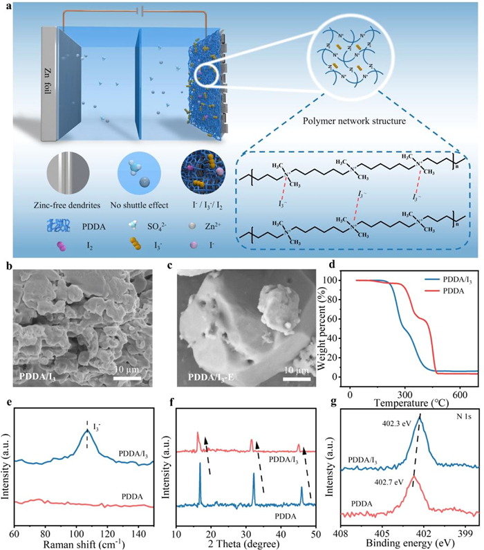
Inspired by the aforementioned background, we have designed a kind of cathodic material of PDDA/I3 based on poly(diallyl dimethylammonium) (PDDA), in which the quaternary ammonium cations have strong electrostatic interaction with polyiodide species. As illustrated in Fig. 1a, the polymeric network formed by PDDA chains can effectively immobilize iodine species on the cathode side, promoting the reversible redox conversion among I-, I3- and I2 species. This confinement will significantly suppress the shuttle effect of polyiodides and mitigate the risk of zinc dendrite formation. The synthesis route of PDDA/I3 is detailly described in Fig. S1 (Supporting information). In order to obtain the materials with excellent performance, we explore two fabrication strategies by reacting PDDA with iodine solution respectively in aqueous and ethanol media, yielding two kinds of samples: PDDA/I3-W (referred to as PDDA/I3 hereafter) and PDDA/I3-E. Electrochemical evaluations reveal that the PDDA/I3 sample prepared in water outperforms its counterpart PDDA/I3-E prepared in ethanol medium in terms of specific capacitance, rate capability, and cycling stability (Figs. S2 and S3 in Supporting information). We attribute this performance difference to the lower polarity of ethanol, which induces aggregation of PDDA polymer chains, thereby reducing the exposure of active adsorption sites for iodine fixation. This hypothesis is supported by scanning electron microscopy (SEM) images: The PDDA/I3 sample exhibits a porous morphology which is conducive to iodine adsorption and transport, whereas the PDDA/I3-E sample displays a denser structure that may hinder effective iodine uptake and release (Figs. 1b and c). Furthermore, according to the N2 adsorption/desorption isotherm curves, we can find that PDDA/I3 has larger specific surface area and pore volume than PDDA/I3-E, which facilitate the infiltration of electrolyte and the reaction dynamics (Fig. S4 in Supporting information). To identify the chemical formation of iodine in the PDDA/I3 cathode and assess the retention of chloride ions, we have performed Raman and X-ray photoelectron spectroscopy (XPS) measurements. The Raman spectrum of PDDA/I3 shows a pronounced band at ≈110 cm-1, which is characteristic of the symmetric stretch of triiodide (I3-) (Fig. 1e). The I 3d XPS region further reveals binding-energy features corresponding to polyiodide species rather than molecular I2 or simple iodide, confirming that iodine exists predominantly as I3- within the PDDA/I3 cathode (Fig. S5a in Supporting information). Semi-quantitative analysis of the XPS survey spectra shows that the Cl atomic fraction decreases sharply from 8.17 at% in pristine PDDA to 0.39 at% after being reacted with iodine solution (Fig. S5b in Supporting information), indicating that chloride is almost completely replaced by iodine species, with only trace amounts remaining. These results demonstrate that PDDA can effectively bind and stabilize triiodide, which accounts for the strong suppression of polyiodide migration in the composite cathode.
Figure 1
Figure 1.
(a) Schematic illustration of the design principle of the Zn-I2 battery and PDDA/I3 cathode optimization strategy. The SEM images for (b) PDDA/I3 and (c) PDDA/I3-E. (d) TGA curves of the PDDA and PDDA/I3 in N2 atmosphere. (e) Raman spectra of PDDA and PDDA/I3 (f) XRD patterns for the PDDA/I3 and initial PDDA. (g) the ex-situ N 1s XPS for PDDA/I3 and initial PDDA.
To further elucidate the interaction mechanism between PDDA and polyiodide species, we have conducted a set of comprehensive characterization and analysis. Thermogravimetric analysis (TGA) reveals that pristine PDDA exhibits a higher onset decomposition temperature, whereas PDDA/I3 undergoes earlier weight loss and is fully decomposed at ~400 ℃. The reduced thermal stability is attributed to the strong oxidizing nature of I3-, which accelerates backbone degradation. Notably, PDDA/I3 shows a higher residual mass than pristine PDDA, suggesting iodine-induced crosslinking of the polymer matrix (Fig. 1d). These results indicate that polyiodide adsorption alters the original chemical environment of PDDA, accompanied by Cl- replacement, consistent with the XPS findings, and point to strong chemical rather than purely physical interactions between PDDA and I3-. Compared with pure iodine, which sublimes between 65 ℃ and 140 ℃, the PDDA/I3 sample exhibits two distinct weight-loss stages: The first stage (200–300 ℃) corresponds to the sublimation of iodine, with an estimated iodine content of ~40 wt% (Fig. S6 in Supporting information), while the second stage arises from decomposition of the PDDA framework. This high temperature shift indicates a significant enhancement in thermal stability due to the incorporation of iodine into the PDDA matrix, suggesting a strong interaction between PDDA and iodine species. To gain insight into the structural environment changes, X-ray diffraction spectrometer (XRD) has been performed before and after the reaction between PDDA and iodine solution (Fig. 1f). Compared to pristine PDDA, the XRD pattern of the PDDA/I3- composite exhibits a distinct shift of the diffraction peak to a lower angle, which corresponds to an expansion of the interchain spacing. This provides clear evidence that I3- anions have been successfully intercalated into the interlamellar spaces of the PDDA [48]. To further verify the nature and binding state of the interaction between PDDA and I3- ions, XPS analysis has been conducted (Fig. 1g). The N 1s peak shows a significant shift, implying that the introduction of iodine species alters the electron density around the quaternary ammonium nitrogen atoms [49]. This shift confirms the anchoring effect of I3- and I2 species on PDDA, which increase the electron density of N atom in PDDA. This spectral change suggests a strong electronic interaction between the quaternary ammonium groups and the polyiodide species.
In order to study the actual performance of the material in the battery, we assemble it into coin batteries to carry out a series of electrochemical tests under the voltage window of 0.4-1.6 V (vs. Zn/Zn2+). It has been demonstrated that TBAI3 has promising performance as an electrode material in Li-I2 batteries [50], so it is here used as the counterpart in AZIBs to validate the effectiveness of quaternary ammonium groups and highlight the synergistic advantage of the polymer network structure. The cyclic voltammetry (CV) curves of the battery are obtained at different scan rates from 0.1 mV/s to 1.0 mV/s (Figs. 2a and d). As shown in the figure, both kinds of cells assembled by materials of PDDA/I3 and TBAI3 have two pairs of peaks, p1/p4 and p2/p3, which indicates that the oxidation-reduction of iodine species has gone through two stages [20]:
I3−+2e−↔3I−
(1)
3/2I2+e−↔I3−
(2)
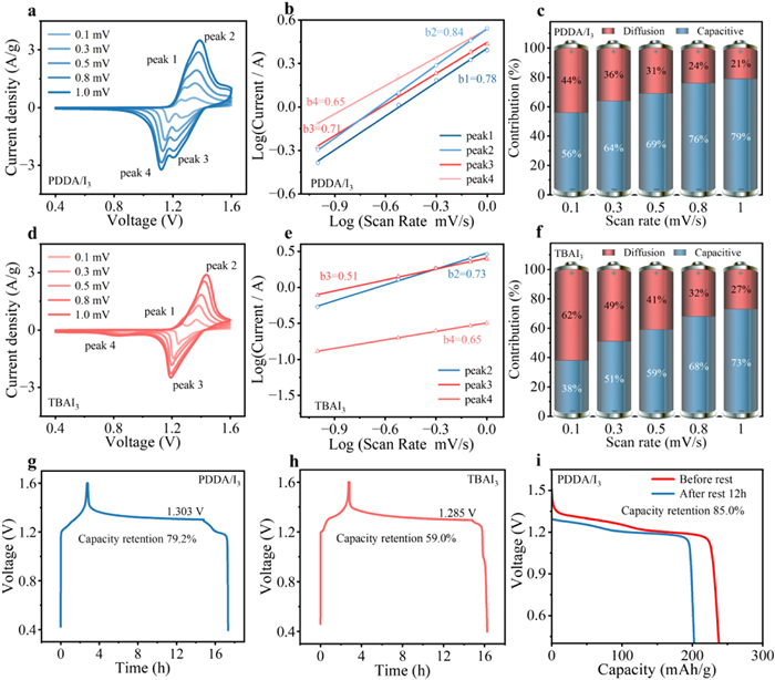
where the peaks of p1/p4 correspond to the conversion of I-/I3- (Eq. 1), and p2/p3 correspond to the conversion of I3-/I2 (Eq. 2). Although two sets of peaks have been observed for both materials, the positions of redox peaks are very different. The CV curves of Zn||PDDA/I3 are more symmetrical than those of Zn||TBAI3, showing its excellent reversibility in the redox reaction process. Due to the strong adsorption performance of PDDA for iodine species, the Zn||PDDA/I3’s peaks of p1/p4 are more distinguished than Zn||TBAI3, and with the increase of scanning rates, the peaks of p1 and p2 tend to merge. It is worth noting that in Fig. 2d, the p4 peak has a significant shift, which may be caused by the limited binding ability of I3- to TBA, leading to the easy dissolution of small molecule in aqueous solution. Therefore, during the discharge process, the dissolving and diffusing I3- ions need a high potential difference to migrate to the cathode for reaction. When it migrates to the anode and react, the voltage has been reduced to around 0.8 V. In this case, a relative weak peak of I3-/I- appears, while the cell assembled by using PDDA/I3 as cathode will not appear the peak around 0.8 V due to its strong binding force to I3- ions. The difference in the CV curves of the two materials is particularly noticeable at low scan rate. In Fig. S7 (Supporting information), it can contrast the CV curves of Zn-I2 batteries with PDDA/I3 and TBAI3 as cathodes at 0.1 mV/s. Notably, the PDDA/I3 cathode displays a narrower redox voltage gap, highly symmetrical redox peak shape, and larger area corresponding to redox reaction region, manifesting its faster reaction kinetics, higher energy density, and more reversible cycle behavior [51], respectively. Meanwhile, the large redox potential shift of I3-/I- (~0.95 V) for the battery with TBAI3 as cathode is more obvious at low scan rate. This supports the hypothesis that a larger overpotential is required to drive the diffusing iodine species toward the cathode under slow scan conditions.
Figure 2
Figure 2.
CV curves of (a) Zn||PDDA/I3 and (d) Zn||TBAI3 at the scan rates of 0.1-1.0 mV/s, the calculated b values corresponding to the redox peaks for (b) Zn||PDDA/I3 and (e) Zn||TBAI3, the calculated capacitive contribution ratios for (c) Zn||PDDA/I3 and (f) Zn||TBAI3 at 0.1-1.0 mV/s. The potential retention after the cells is rested for 12 h for (g) Zn||PDDA/I3 and (h) Zn||TBAI3 batteries. (i) Comparison of discharge capacities before and after a 12 h rest at 0.1 A/g.
According to the peak currents in the CV curves at different scan rates, the b values for Zn||PDDA/I3 and Zn||TBAI3 can be calculated according to Eqs. S2-S5 (Supporting information). In accordance with the references [52], b value is usually used to evaluate the kinetic mechanism of electrode reaction. When b value is close to 1, the electrochemical reaction is mainly affected by capacitive behavior. When b value is close to 0.5, the diffusion process will dominate the reaction. The b values of the two kinds of batteries are between 0.5 and 1.0, indicating that they are both affected by surface control and diffusion control. The b value for Zn||PDDA/I3 system is close to 1.0 (Fig. 2b), while for Zn||TBAI3 is close to 0.5 (Fig. 2e, because its p1 peak is not obvious at high scanning speed, b1 value is not calculated), indicating that PDDA significantly improves the surface capacitance behavior of electrode response, which may be because its strong adsorption performance limits the diffusion and migration of polyiodide species and improves the efficiency of electrochemical reaction. Meanwhile, the pseudo-capacitive contribution ratio for the Zn||PDDA/I3 and Zn||TBAI3 batteries at different scan rates have been quantitatively calculated (Fig. S8 in Supporting information). In detail, the capacitive contribution ratios for PDDA/I3 are 56%, 64%, 69%, 76% and 79% at the scan rates of 0.1, 0.3, 0.5, 0.8 and 1.0 mV/s (Fig. 2c) respectively, which are higher than that for Zn||TBAI3 throughout the scan rates (Fig. 2f), which can be attributed to the strong adsorption capability of cationic ions in the polymer structure for the iodine species during the cycling process. To further assess cathode performance, we have evaluated the self-discharge behavior (a key indicator of polyiodide immobilization) for the fully charged cells [53,54], the discharging curves will be recorded after the cells have been rested for 12 h. As shown in Figs. 2g and h, the open-circuit voltage (OCV) of Zn||PDDA/I3 also declines less compared to Zn||TBAI3 (1.303 V vs. 1.285 V), reinforcing the superior anti-self-discharge capability imparted by PDDA. Additionally, Zn||PDDA/I3 retains 85.0% of its pre-rest discharge capacity (Fig. 2i), which is superior to that of Zn||TBAI3 (59%, Fig. S9 in Supporting information), indicating minimal capacity decay and effective polyiodide fixed.
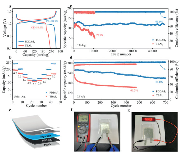
Following the self-discharge analysis, galvanostatic charge-discharge (GCD) profiles have been recorded to evaluate capacity output and reaction reversibility, GCD measurements (Fig. 3a) shown that the Zn||PDDA/I3 cell can deliver a high capacity of 271.2 mAh/g at current density of 0.1 A/g, outperforming the Zn||TBAI3 cell (231.4 mAh/g). The reduced capacity of the TBAI3 system is mainly attributed to dissolving polyiodide into the electrolyte during cycling, leading to active material loss and utilization efficiency decreased. In addition to high capacity, Zn||PDDA/I3 also demonstrates a superior Coulombic efficiency (CE). At current density of 0.1 A/g, it can achieve a CE of 98.5%, significantly higher than 86.6% observed for Zn||TBAI3. Generally, CE serves as an indicator of energy conversion efficiency and is influenced by current density and the cathode’s ability to immobilize polyiodide. At low current densities, full redox reactions process needs enough time, and the generated polyiodides tend to dissolve into the electrolyte, exacerbating shuttle effects. However, as the current density increases, CE value will be improved correspondingly due to the shorter time required to complete the oxidation-reduction reaction compared with the diffusion time of polyiodide ions. The robust CE of Zn||PDDA/I3 under low current density reveals the strong electrostatic interaction between cations in PDDA and polyiodides, effectively suppressing the shuttle effect.
Figure 3
Figure 3.
Comparison of the properties of different materials in batteries. (a) GCD curves at 0.1 A/g. (b) Rate capability at various current densities from 0.2 A/g to 3.0 A/g. (c) Cycling stability of the devices at a current density of 3.0 A/g. (d) Cycling stability of the devices at a current density of 0.1 A/g. (e) Schematic illustration of a pouch cell. (f) The voltage of the pouch battery. (g) Digital photographs of pouch cells used to power an LED panel.
The Zn-I2 cells assembled with different cathode materials have been examined at different current densities from 0.2 A/g to 3.0 A/g to investigate their rate performance (Fig. 3b). Obviously, Zn||PDDA/I3 cell can perform a much higher specific capacity (240.2 mAh/g at 0.2 A/g and 118 mAh/g at 3.0 A/g) than Zn||TBAI3 cell (195.7 mAh/g at 0.2 A/g and 110.6 mAh/g at 3.0 A/g), after 45 cycles of charge/discharge at different current densities, the capacity of Zn||PDDA/I3 can almost be completely recovered when current density returns to 0.2 A/g, manifesting good rate capability, which may be attributed to the strong electrostatic adsorption ability of the abundant cationic groups in PDDA for polyiodides. Thanks to the effective restriction of PDDA on the shuttling effect of polyiodides, the Zn||PDDA/I3 cell yields impressive capacity retention of 91.0% of its initial capacity after 46,000 cycles at 3.0 A/g. In contrast, the Zn||TBAI3 cell can only retain 39.3% after 10,500 cycles (Fig. 3c). Meanwhile, the Zn||PDDA/I3 cell yields impressive capacity retention of 84.0% of its initial capacity after 700 cycles at 0.1 A/g (~2000 h, Fig. 3d), which also far surpasses that of the Zn||TBAI3 in terms of capacitance retention (66.3%). To evaluate the performance under practical high-loading conditions, both the active-material mass and the ZnI2 concentration in the electrolyte have been increased fourfold, resulting in an iodine loading of 7.92 mg/cm2 on the cathode. Under these heavy-loading conditions, the Zn||PDDA/I3 cell still retains a high Coulombic efficiency of 98.56% at 0.1 A/g and exhibits excellent cycling stability, preserving 98.5% of its capacity after 1600 cycles at 3.0 A/g (Fig. S10 in Supporting information). These results confirm that PDDA maintains strong polyiodide adsorption and effectively suppresses the shuttle effect even at demanding iodine loadings, demonstrating the robustness and practical applicability of the proposed strategy.
The excellent performance of PDDA/I3 in coin cells inspired us to further explore its potential in practical applications. Therefore, we assemble PDDA/I3-based pouch cells, which can be fabricated under atmospheric conditions without the need of complex processing steps [55]. As shown in Fig. 3e, the internal structure of the pouch cell is compact and well-integrated. Subsequent testing reveals that the fully charged pouch cell maintains an open-circuit voltage of approximately 1.5 V after being charged, a voltage level compatible with most commercially available electronic devices (Fig. 3f). Remarkably, a single pouch cell is capable of powering an LED panel (Fig. 3g), demonstrating not only its high-power density but also promising potential for real-world applications. To quantify device-level performance, 3.0 × 3.0 cm pouch cells have been assembled and tested by galvanostatic charge–discharge at 0.1 A/g. The pouch cell delivers a stable discharge capacity of 268.7 mAh/g with an average Coulombic efficiency (CE) of 98.3% (Fig. S11a in Supporting information), and the capacity remains nearly unchanged after 70 cycles (~280 h) (Fig. S11b in Supporting information). Based on the measured discharge capacity and voltage profile (Fig. S11c in Supporting information), the energy density can be calculated to be 258.9 Wh/kg. The pouch-cell performance is comparable to that of the corresponding coin cell, further demonstrating the practical applicability of the PDDA/I3 electrode. Some published representative cathode materials for zinc iodine batteries have been compared with our work in terms of cycle number, specific capacity, energy density (derived from Fig. S12 in Supporting information, calculated as described in the Supporting Information.), and capacity retention to evaluate the comprehensive performances of batteries. Obviously, Zn||PDDA/I3 shows impressive improvements in these aspects (Tables S1-S3 in Supporting information).
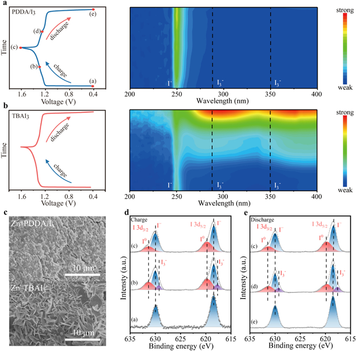
In situ ultraviolet-visible (UV-vis) spectroscopy and X-ray photoelectron spectroscopy (XPS) analyses have been conducted to elucidate the origin of the excellent cycling stability of the Zn||PDDA/I3 battery. Specifically, the PDDA/I3 cathode, zinc anode, and electrolyte are assembled into a sealed battery configuration inside a cuvette (Fig. S13 in Supporting information), and the UV-vis spectra of the electrolyte are continuously monitored during the charge/discharge process. The in-situ UV-vis results reveal that no characteristic absorption peaks of I3- (at 288 and 350 nm) appeared during the cyclic measurement of the Zn||PDDA/I3 battery [36], indicating negligible release or accumulation of I3- species in the electrolyte. In contrast, the Zn||TBAI3 battery exhibits progressively intensified I3- absorption peaks throughout cyclic test, this phenomenon is particularly pronounced when TBAI3 is used as the electrode material, during the charging process, the electrolyte visibly turned pale yellow, clearly signifying the diffusion of polyiodides change easily observable to the naked eyes, which is a stark contrast to the remained colorless and transparent throughout the entire charging process when PDDA/I3 is employed as cathode material (Fig. S14 in Supporting information). The phenomenon indicates that there is significant leakage and accumulation of I3- in the electrolyte in Zn||TBAI3 (Figs. 4a and b). These free I3- species can follow two unfavorable pathways: (1) Migrating toward the zinc anode and engaging in parasitic reactions, leading to electrode corrosion and zinc dendrite formation [56]; or (2) failing to return to the cathode for reversible redox reactions, resulting in the formation of "dead iodine" and loss of active material [57]. The combined effects of the two phenomena will accelerate capacity degradation and cycle life dramatical decrease. The conclusion is further supported by post-cycling SEM image of the zinc anode surfaces. As shown in Fig. 4c, after 50 charge/discharge cycles, compared with bare zinc (Fig. S15 in Supporting information), the surface of the Zn foil in the Zn||TBAI3 battery is covered with abundant dendritic structures, while the Zn foil from the Zn||PDDA/I3 battery remains smooth and compact. This stark contrast indicates severe parasitic reactions and uncontrolled zinc deposition in the absence of effective I3- confinement [58]. To further substantiate the morphological observations, XRD has been performed on Zn anodes after 50 cycles (Fig. S16 in Supporting information). The Zn foil from the Zn||TBAI3 cell exhibits distinct diffraction peaks assignable to Zn4SO4(OH)6·H2O (ZSH), indicating extensive formation of corrosion by-products driven by polyiodide shuttling and the resulting perturbation of the local interfacial environment. In contrast, the Zn anode from the Zn||PDDA/I3 cell shows only negligible ZSH signals, confirming that the PDDA/I3 cathode effectively confines I3-, suppressing iodine shuttle and attendant parasitic reactions, and thereby preserving smooth, compact Zn deposition and anode integrity during cycling. Upon opening the battery, a pronounced I3- shuttle effect can be observed in the control system (Fig. S17 in Supporting information). In contrast, this phenomenon is significantly suppressed in the Zn||PDDA/I3, indicating that PDDA effectively inhibits the migration of polyiodide species. Therefore, PDDA functions as an effective host for iodine, capable of immobilizing I3- species and suppressing their dissolution and shuttle behavior. This inhibition of side reactions contributes to the extended lifespan and superior cycling performance of the Zn||PDDA/I3 battery compared to its Zn||TBAI3 counterpart.
Figure 4
Figure 4.
The corresponding in situ UV-vis electron adsorption spectra for the (a) Zn||PDDA/I3 and (b) Zn||TBAI3, (c) The Zn SEM image of Zn||PDDA/I3 and Zn||TBAI3 after cycles. The well-fitting high-resolution I 3d XPS in cathode of PDDA/I3 during (d) charge and (e) discharge corresponding to the states at (a).
Building upon the UV-vis results, XPS is further employed to explore the valence evolution of iodine species in the PDDA/I3 cathode at different stages of charging. Across all states, two prominent peaks around 630 and 620 eV are consistently observed, corresponding to the I 3d3/2 and I 3d5/2 orbitals, indicating the persistent presence of iodine species on the cathode surface. At the 1.3 V charged plateau, the XPS spectra reveals the coexistence of I3- (617.7 and 629.3 eV) and I0 (619.7 and 631.3 eV) [57], suggesting a partial oxidation of I3- to molecular iodine. Upon further charging to 1.6 V, the I3- signals are disappeared completely, and only peaks corresponding to I0 are detected (Fig. 4d). This indicates that I3- is fully oxidized to I0. This result confirms that the PDDA matrix can effectively retain I3- at the cathode interface, enabling complete valence conversion without dissolution into the electrolyte. Upon subsequent discharging to 0.4 V, the I0 signals are replaced by characteristic peaks of I- (at 618.4 and 630.0 eV), confirming the reduction of I0 to I- (Fig. 4e). Together with the in situ UV-vis results, these findings demonstrate that PDDA efficiently immobilizes I3- at the cathode surface, strongly suppressing the polyiodide species shuttle effect. Moreover, the well-defined redox pathway (I0 → I3- → I-) demonstrates excellent electrochemical reversibility, contributing to enhanced cycling stability and energy efficiency of the Zn-I2 battery system.
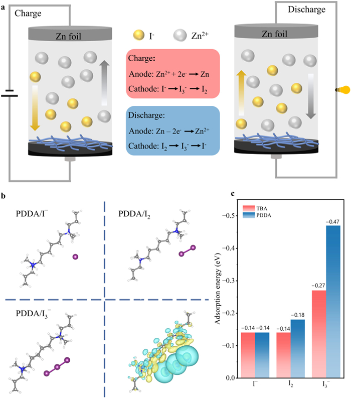
Based on the evolution of elemental signals observed in cathodic XPS spectra during the charge/discharge process, along with the stepwise changes in iodine valence states, the energy storage mechanism of the Zn-I2 battery can be elucidated as a redox-coupled ionic storage mechanism. This mechanism involves the reversible redox transformation of iodine species and the plating/stripping behavior of Zn2+ ions. As illustrated in the schematic (Fig. 5a), during discharge, molecular iodine (I2) is first reduced to triiodide (I3-), and subsequently to iodide (I-). Meanwhile, Zn2+ ions are released from the zinc anode into the electrolyte. Upon charging, the I- ions are reoxidized to I3- and then to I2, while Zn2+ ions in the electrolyte are reduced and deposited back onto the zinc surface. This synchronized redox–ionic process enables highly reversible electrochemical behavior, forming the foundation for stable and efficient energy storage in aqueous Zn-I2 batteries.
Figure 5
Figure 5.
(a) The proposed hybrid energy storage mechanisms of Zn||PDDA/I3. (b) DFT calculations of adsorption energy for PDDA/I-, PDDA/I2 and PDDA/I3-. And the corresponding electron density difference distribution of PDDA/I3-. (c) Adsorption energies of PDDA and TBA with I-, I2, and I3-.
To further elucidate the underlying mechanism by which PDDA effectively confines iodine species, density functional theory (DFT) calculations have been conducted to compare the adsorption energies of TBA and PDDA with I-, I2 and I3-. To simplify the computational process, two representative segments of the PDDA polymer chain are selected as the model structures (Fig. 5b and Fig. S18 in Supporting information). The results show PDDA exhibits stronger binding affinities, with adsorption energies of -0.18 eV for I2 and -0.47 eV for I3-, stronger than TBA’s -0.14 eV and -0.27 eV, respectively. (Fig. 5c) This enhanced interaction may be attributed to the high density of cationic binding sites and the robust polymeric framework of PDDA. Charge density difference maps further confirm the tight adsorption of I3- on PDDA, as evidenced by pronounced electron density overlap (Fig. 5b). The above-mentioned results reveal that although TBA displays some interaction with iodine species, its relatively weaker adsorption leads to insufficient confinement for iodine species during charge/discharge cycles, allowing polyiodides to migrate from the cathode into the electrolyte. The consistency between theoretical calculations and experimental findings strongly supports when PDDA/I3 is used as a cathode material, PDDA can effectively anchor polyiodide species, suppress their shuttle behavior, minimize the loss of active material, and reduce the risk of polyiodide-induced corrosion on the zinc anode. These insights highlight the potential of PDDA-based polymers in enabling stable and efficient aqueous Zn-I2 batteries.
In summary, we have developed a novel electrode material based on a cationic polymer, which effectively suppresses the polyiodide shuttle effect through its stable network structure and abundant active sites. A series of electrochemical characterizations combining with DFT calculations, have confirmed that the plentiful cationic ions play a crucial role in immobilizing polyiodides. Compared with the quaternary ammonium salt of TBAI3, the polymeric framework clearly contributes to significantly enhanced battery longevity. Benefiting from the synergistic effect of strong electrostatic adsorption and structural confinement, the PDDA/I3 based Zn-I2 battery delivers a high capacity of 271.2 mAh/g and maintains 119.2 mAh/g after 46,000 cycles at 3.0 A/g, corresponding to a capacity retention of 91.0%. This work not only systematically reveals the essential role of PDDA cations in mitigating the polyiodide shuttle effect but also provides a viable strategy for designing high-energy-density and long-lifespan aqueous Zn-I2 batteries. By tailoring the structure and interfacial chemistry of the cathode material, the overall electrochemical performance is significantly improved. This strategy offers and opens new avenues for developing advanced cathode materials of aqueous energy storage devices with excellent universality and scalability.
The authors declare that they have no known competing financial interests or personal relationships that could have appeared to influence the work reported in this paper.
Acknowledgments
The authors thank the National Natural Science Foundation of China (Nos. U21A6004, U21A20172, 52402284, 52403041, and U1510121), the Science and Technology Major Project of Shanxi (No. 202101030201022), Fundamental Research Program of Shanxi Province (No. 202403021222021), and the Open Fund of the Key Lab of Organic Optoelectronics & Molecular Engineering.
Supplementary materials
Supplementary material associated with this article can be found, in the online version, at doi:10.1016/j.cclet.2025.111870.
W. Shang, J. Zhu, Y. Liu, et al., ACS Appl. Mater. Interfaces 13 (2021) 24756. doi: 10.1021/acsami.1c03804
[54]
Y. Wang, X. Jin, J. Xiong, et al., Adv. Mater. 36 (2024) 2404093. doi: 10.1002/adma.202404093
[55]
L. Zhang, H. Ding, H. Gao, et al., Energy Environ. Sci. 18 (2025) 2462–2473. doi: 10.1039/D4EE05873A
[56]
T. Wang, P. Wang, L. Pan, et al., Adv. Energy Mater. 13 (2023) 2203523. doi: 10.1002/aenm.202203523
[57]
F. Wang, J. Tseng, Z. Liu, et al., Adv. Mater. 32 (2022) 2000287.
[58]
L. Hu, C. Dai, Y. Zhu, et al., Energy Environ. Sci. 17 (2024) 5552–5562. doi: 10.1039/d4ee02096k
Figure 1
(a) Schematic illustration of the design principle of the Zn-I2 battery and PDDA/I3 cathode optimization strategy. The SEM images for (b) PDDA/I3 and (c) PDDA/I3-E. (d) TGA curves of the PDDA and PDDA/I3 in N2 atmosphere. (e) Raman spectra of PDDA and PDDA/I3 (f) XRD patterns for the PDDA/I3 and initial PDDA. (g) the ex-situ N 1s XPS for PDDA/I3 and initial PDDA.
Figure 2
CV curves of (a) Zn||PDDA/I3 and (d) Zn||TBAI3 at the scan rates of 0.1-1.0 mV/s, the calculated b values corresponding to the redox peaks for (b) Zn||PDDA/I3 and (e) Zn||TBAI3, the calculated capacitive contribution ratios for (c) Zn||PDDA/I3 and (f) Zn||TBAI3 at 0.1-1.0 mV/s. The potential retention after the cells is rested for 12 h for (g) Zn||PDDA/I3 and (h) Zn||TBAI3 batteries. (i) Comparison of discharge capacities before and after a 12 h rest at 0.1 A/g.
Figure 3
Comparison of the properties of different materials in batteries. (a) GCD curves at 0.1 A/g. (b) Rate capability at various current densities from 0.2 A/g to 3.0 A/g. (c) Cycling stability of the devices at a current density of 3.0 A/g. (d) Cycling stability of the devices at a current density of 0.1 A/g. (e) Schematic illustration of a pouch cell. (f) The voltage of the pouch battery. (g) Digital photographs of pouch cells used to power an LED panel.
Figure 4
The corresponding in situ UV-vis electron adsorption spectra for the (a) Zn||PDDA/I3 and (b) Zn||TBAI3, (c) The Zn SEM image of Zn||PDDA/I3 and Zn||TBAI3 after cycles. The well-fitting high-resolution I 3d XPS in cathode of PDDA/I3 during (d) charge and (e) discharge corresponding to the states at (a).
Figure 5
(a) The proposed hybrid energy storage mechanisms of Zn||PDDA/I3. (b) DFT calculations of adsorption energy for PDDA/I-, PDDA/I2 and PDDA/I3-. And the corresponding electron density difference distribution of PDDA/I3-. (c) Adsorption energies of PDDA and TBA with I-, I2, and I3-.


 DownLoad:

 下载:


 下载:

