School of Material Science and Engineering, College of Chemistry and Chemical Engineering, Institutes of Physical Science and Information Technology, Anhui University, Hefei 230601, China
Received Date:
04 June 2025 Accepted Date:
21 September 2025 Revised Date:
10 September 2025 Available Online:
15 December 2026
Abstract:
Organic polymers have been widely employed as electrode materials for secondary batteries due to their tunable structural flexibility and tailorable electrochemical properties. However, their inherent steric hindrance and dense molecular packing inevitably lower the utilization of active sites, thus resulting in unsatisfactory capacity. Hence, we designed and synthesized a para-substituted triazine-based polyamine (PAN-p) featuring both minimal steric hindrance and a highly porous architecture through rational molecular engineering. The reduced steric hindrance and increased porosity affords a significant improvement in redox reaction kinetics, thereby boosting the Li-storage performance. As a result, the PAN-p anode delivers a high reversible capacity of 780 mAh/g at 0.3 A/g and long life-span over 500 cycles without significant decay. Furthermore, theoretical calculations were conducted to unravel the relationships between steric hindrance and electrochemical performance of PAN derivatives based on the different substitution patterns (para-, meta-, and ortho-positions), offering insights into their distinct electrochemical behaviors. The work provides a promising design of high-performance organic electrode materials for efficient Li-storage.
Lithium-ion batteries (LIBs) have been regarded as a high-efficiency energy storage system due to their superior power density, energy density, reliability, and stability, maintaining their dominance over the past few decades [1,2]. As a critical component of batteries, electrode materials largely determine the overall performance and have remained a central research focus [3,4]. Currently, inorganic electrode materials (e.g., LiFePO4, LiCoO2, LiNixCoxMnxO2, Si, and graphite) dominate practical applications. However, they suffer from energy-intensive synthesis processes, limited natural resource availability, and environmental concerns. In contrast, organic electrode materials have emerged as a promising alternative owing to their abundant elemental availability, structural tunability, environmental friendliness, and high theoretical capacity [5-7].
However, numerous challenges still restrict the electrochemical performance of organic electrode materials, including high solubility [8], poor electronic conductivity [9,10], and inferior stability [11,12]. Currently, numerous efforts have been devoted to addressing these challenges. Among them, low molecular weight organic compounds can be modified through compositing with insoluble and conductive materials, which not only mitigates dissolution issues but also enhances electrode conductivity. Furthermore, heteroatom incorporation (e.g., S, N) [13-16] and pre-lithiation [17,18] have been proven effective in improving activity, electronic conductivity, and cycling stability of organic electrode materials. While these approaches significantly enhance electrochemical behavior, the most direct method for organic materials remains the precise design and synthesis of structurally differentiated molecules [19,20]. For example, Zhang et al. designed a series of conjugated microporous polymers (CMPs) with optimized thiophene content and specific surface area, and demonstrating improved electrochemical performance [21]. Wang et al. systematically investigated the influence of carboxylate positioning in pyrazine dicarboxylate frameworks on lithium storage behavior, and offering a rational design of structural configuration for high-performance LIBs [22]. Zhang’s group synthesized a triazine-based polyimide covalent organic framework cathode, which exhibits a large capacity of 220 mAh/g and high stability [23]. Additionally, aromatic imides [24,25], azo-linked polymers [26,27], and carbonyl-rich polymeric systems [28,29] have further been explored and revealing that electrochemical performance is critically dependent on their molecular architecture.
These studies conclusively demonstrate molecular engineering as a powerful strategy for optimizing organic electrode materials. Among them, steric effects play a critical role in governing the pore architectures, surface area distribution, and morphological features, which directly related to the electron/Li+ transport pathways, active site accessibility, and electrochemical kinetics [30]. Therefore, systematic investigation of steric-structure-performance relationships enables optimized electrochemical performance of organic electrodes at the molecular scale.
This work synthesized a series of triazine-based polyamine polymers using bis(4,6-diamino-s-triazin-2-yl) benzene derivatives with varying substitution patterns as active centers, and systematically investigating the structure-performance relationships. Combined experimental and theoretical analyses revealed distinct physicochemical and electrochemical behaviors among the structural variants. Among them, the para-substituted PAN-p1 exhibits excellent electrochemical performance due to its minimal steric hindrance and highest specific surface area. At a current density of 0.3 A/g, it maintains a capacity of 780 mAh/g over 500 cycles. Even at 1 A/g and over 1000 cycles, its capacity remains at 324 mAh/g with almost no degradation. In contrast, the ortho-connected PAN-o1 shows a lower capacity due to its greater steric hindrance. Another series, PAN-p2, PAN-m2, and PAN-o2 still follows above pattern. This finding demonstrates the steric hindrance as a critical parameter governing the electrochemical performance of organic electrode, and provides guidelines for the performance enhancement through molecular design. Detailed experimental methods are provided in the supporting information [31,32].
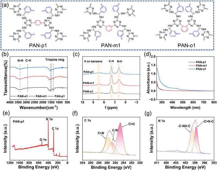
Three triazinotetramine monomers (p-BzDAT, m-BzDAT, and o-BzDAT) were prepared by a one-pot condensation method, and presenting para-, meta-, and ortho-substituted configurations, respectively (Fig. S1a in Supporting information). Afterward, the structures of these monomers were confirmed by FT-IR and 1H NMR. The FT-IR exhibited a strong absorption peak around 1665 cm-1, which can be attributed to the in-plane deformation vibration of the -NH2 group (Fig. S2b in Supporting information). Further 1H NMR analysis provided further confirmation of successful monomer synthesis of p-BzDAT, m-BzDAT and o-BzDAT (Fig. S3 in Supporting information). After polycondensation of these monomers with isophthalenaldehyde, a series of triazine polymers (PAN-p1, PAN-m1 and PAN-o1) were obtained (Fig. 1a and Fig. S1b in Supporting information).
Figure 1
Figure 1.
(a) The molecular structures of PAN-p1, PAN-m1, and PAN-o1. (b) FT-IR spectra and (c) solid-state 1H NMR spectra of PAN-p1, PAN-m1, and PAN-o1. (d) The UV–vis absorption spectrum of the electrolytes after soaking the PAN-p1, PAN-m1, and PAN-o1. (e) XPS survey spectrum of PAN-p1 and corresponding high-resolution spectra of (f) C 1s and (g) N 1s.
Afterward, these polymers structures were confirmed by FT-IR. The strong absorption peaks around 1701 cm-1 belonged to the -CHO groups in terephthalendehyde and isophthalenaldehyde (Fig. S2a in Supporting information), but the obvious reactant characteristic peaks near 1665 and 1701 cm-1 were not observed in PANs, indicating that the reaction groups were completely transformed after polymerization. Meanwhile, the absorption peaks of N-H/C-H (3410/2917 cm-1), triazine rings (1560, 1468, and 1367 cm-1), and aromatic C-H (814 cm-1) can be observed in Fig. 1b, confirming the synthesis of PANs. Afterward, the solid 1H NMR spectra showed the appearance of the peak at 7.2–8 ppm corresponding to the hydrogen on the benzene ring. The peak near 4 ppm was caused by the hydrogen on the carbon attached to the benzene ring. The peak at 1.8 ppm can be assigned to the hydrogen on the imino group (Fig. 1c), further supporting the results of FT-IR. Besides, elemental analysis also indicated a good agreement between experimental and theoretical nitrogen content for PANs (Table S1 in Supporting information). Subsequently, XPS testing further confirmed the successful synthesis of PANs. In the XPS full scan, three peaks corresponding to C 1s, N 1s, and O 1s can be clearly observed (Fig. 1e). Among them, the C 1s of PAN-p1 shows the co-existence of C=C (284.8 eV), C–N (286.8 eV) in the benzene ring, and C=N (287.7 eV) in the triazine ring (Fig. 1f). Further, N 1s spectrum also exhibits the characteristic peaks of C=N bond of the triazine ring and C–N bond of the triazine ring to the benzene ring center at 398.52 and 399.74 eV (Fig. 1g), Similarly, the same peaks appear in the C 1s and N 1s spectra of PAN-m1 and PAN-o1, respectively (Fig. S4 in Supporting information). In conclusion, these characterization results supported the successful synthesis of three PANs.
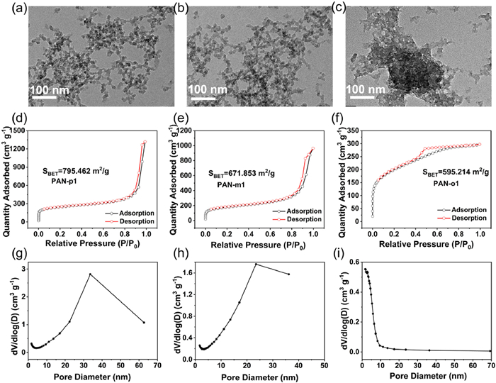
Subsequently, to investigate the solubility of these PANs, the UV–vis absorption spectra was carried out. As shown in Fig. 1d and Fig. S5 (Supporting information), PAN-o1 soaked electrolyte exhibits a weak peak and significant color change, indicating its solubility. In contrast, PAN-p1 and PAN-m1 exhibited almost no peaks and colorless, demonstrating their good stability in the electrolyte. Additionally, TGA curves were performed to explore their decomposition behavior and confirm their good thermal stability (Fig. S6 in Supporting information). As shown in Figs. 2a–c and Figs. S7a-c (Supporting information), SEM and TEM images reveal that all PANs are composed of irregular nanoparticles. Among them, PAN-p1 and pan-m1 represent well-dispersed porous networks with strong particle sensitivity. In contrast, PAN-o1 presents dense packing with poor dispersion and weak particle sensitivity. Afterward, the porosity of these PANs was investigated using nitrogen adsorption-desorption techniques (Figs. 2d–i). Both PAN-p1 and PAN-m1 display type Ⅳ isotherms, indicating their mesoporous structure inside. In contrast, PAN-o1 exhibits a characteristic type Ⅰ isotherm, suggesting a significant microporous structure. Pore size distribution analysis further confirms that PAN-p1 and PAN-m1 are dominated by mesopores, whereas PAN-o1 is primarily composed of micropores (Figs. 2g–i). The pores with uniform size and shape are conducive to facilitating electrolyte accessibility and maximizing the electrode-electrolyte contact area without compromising volume [33]. Additionally, the specific surface areas of PAN-p1, PAN-m1, and PAN-o1 were calculated, yielding values of 795.462, 671.853, and 595.214 m2/g, respectively. Among these, PAN-p1 exhibits the highest specific surface area, which is consistent with the SEM and TEM observations. Therefore, based on the advantageous combination of high specific surface area, porous structure, and oriented connectivity, PAN-p1 is expected to deliver more superior Li-storage performance.
Figure 2
Figure 2.
TEM image of (a) PAN-p1, (b) PAN-m1, (c) PAN-o1. N2 adsorption-desorption isotherms and pore-size distribution of (d, g) PAN-p1, (e, h) PAN-m1, and (f, i) PAN-o1.
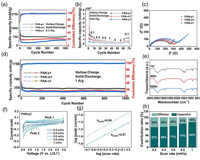
Subsequently, PANs were assembled as the working electrode with lithium metal as the counter electrode in 2032-type coin cells to study their electrochemical performance. Firstly, the cycling performance of PAN-p1, PAN-m1, and PAN-o1 was evaluated at 0.3 and 1 A/g (Figs. 3a and d). At 0.3 A/g, PAN-p1, PAN-m1, and PAN-o1 deliver reversible capacities of 780, 640, and 380 mAh/g after 500 cycles, respectively. When the current density increased to 1 A/g, their reversible capacities decreased to 324, 240, and 195 mAh/g, respectively. Notably, PAN-p1 exhibits superior performance, which can be attributed to its higher specific surface area, which not only exposes abundant active sites but also effectively accommodates the strain from the Li+ insertion/extraction [34]. Subsequently, rate performance further confirmed PAN-p1’s outstanding performance (Fig. 3b). It exhibited reversible capacities of 1678 (5th cycle), 917, 712, 571, 355, and 277 mAh/g at current densities ranging from 0.1 A/g to 5 A/g, respectively. When the current density returns to 0.1 A/g, a capacity 1413 mAh/g can be still maintained. By contrast, PAN-m1 and PAN-o1 exhibited lower initial reversible capacities of 1093 and 517 mAh/g, respectively. Afterward, the electrochemical impedance spectroscopy (EIS) of PANs was measured and revealed that PAN-p1 possessed a lowest charge transfer resistance (271.9 Ω) compared to those of PAN-m1 (301.4 Ω) and PAN-o1 (342.2 Ω) (Fig. 3c), indicating a faster charge transfer kinetics in the PAN-p1 electrode. This result is well consistent with the rate performance and can be attributed to its high surface area and porous structure, which enhance the electrochemical reaction interface and shorten the ion diffusion paths [35]. Furthermore, after one cycle, significant differences were found between the infrared spectra of the of PAN-p1 electrode material and the original of PAN-p1. The C=N peak at 1590 cm-1 weakened, while the N-Li peak at 1430 cm-1 strengthened, indicating the formation of SEI film (Fig. S16 in Supporting information). FT-IR spectroscopy tests were also conducted on PAN-p1 at different cycling stages after the formation of the SEI film, revealing almost identical spectra, which indicates its excellent structural stability during the cycling process (Fig. 3e) [23]. The formation of the SEI film also leads to a significant decrease in the battery's reversible capacity. PAN-p1 material, due to its high specific surface area (Fig. 2d, 759.462 m2/g) and abundant active sites, exhibits extremely high lithium-ion intercalation/extraction capacity during the first charge-discharge cycle, thus providing very high initial capacity (Fig. 3b). However, it is precisely this high specific surface area that brings significant side effects: A large amount of exposed active surface reacts violently with the electrolyte, continuously promoting the formation and growth of the SEI film (Fig. S16). This process irreversibly consumes a large number of lithium ions and electrolyte components, leading to obvious irreversible capacity loss in the first cycle. Therefore, from the second cycle, the effective active material and lithium ions available for charge-discharge cycles are greatly reduced, resulting in a noticeable decline in the actual reversible capacity of the battery, which gradually stabilizes.
Figure 3
Figure 3.
(a) The cycling performance of PAN-p1, PAN-m1, and PAN-o1 at 0.3 A/g. (b) The rate performance of PAN-p1, PAN-m1, and PAN-o1. (c) EIS plots of PAN-p1, PAN-m1, and PAN-o1. (d) The cycling performance of PAN-p1, PAN-m1, and PAN-o1 at 1.0 A/g. (e) Ex-situ FT-IR spectra of PAN-p1 after different cycles. (f) CV curves at different scan rates, (g) relationships between peak current and scan rates, and (h) calculated capacitive contribution for PAN-p1.
To further investigate the electrochemical kinetics of PAN-p1, PAN-m1, and PAN-o1, CV curves were collected at different scan rates ranging from 0.2 mV/s to 1.0 mV/s (Fig. 3f). Afterward, the relationship between the peak current density and sweep rate can be described using the following formula [36]:
i=avb
(1)
logi=loga+blogv
(2)
i=k1v+k2v1/2
(3)
In the formula, i represents the peak current (Eq. 1), a and b are the parameters, and v denotes the scan rate (Eq. 2). The value of b can be used to assess the capacitive contribution. b = 0.5 indicates a diffusion-controlled process, while b = 1.0 signifies a surface-controlled process [34]. After calculation, the b-values for PAN-p1, PAN-m1, and PAN-o1 are 0.94/0.87, 0.93/0.86, and 0.92/0.84, respectively (Fig. 3g and Fig. S8 in Supporting information). Notably, the b-values increase in the order PAN-o1 < PAN-m1 < PAN-p1, indicating the most pronounced surface-controlled capacitive behavior in PAN-p1. Afterward, the corresponding capacitive contribution to the total capacity can be calculated using Eq. 3. As the scan rate increases from 0.2 mV/s to 1.0 mV/s, the capacitive contribution ratios of the PAN-p1, PAN-m1, and PAN-o1 increase to 84%, 77%, and 66%, respectively (Fig. 3h and Fig. S8), demonstrating excellent reaction kinetics [37].
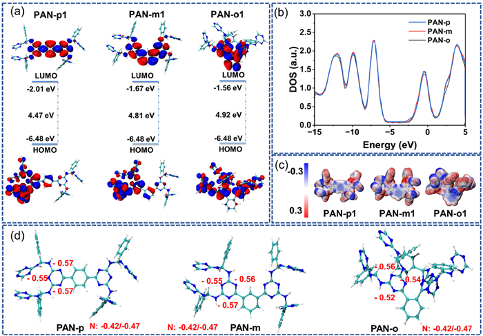
To further investigate the superior electrochemical performance of PAN-p1 electrodes, density functional theory (DFT) calculations were conducted. Firstly, the structures of PAN-p, PAN-m, and PAN-o were optimized using the Gaussian 16 software package at the B3LYP/6–31G** level. Subsequently, the molecular orbitals and density of states (DOS) were analyzed with Multiwfn program. The DFT results reveal that PAN-p has a lower LUMO energy level (−2.01 eV) and smaller energy gap (4.47 eV) compared to PAN-m (−1.67, 4.81 eV) and PAN-o (−1.56, 4.92 eV) (Fig. 4a). Such features indicate that PAN-p has enhanced electron affinity and electronic conductivity than PAN-m and PAN-o, which can facilitate the transfer of electrons and Li+ [38]. DOS analysis reveals that the valence bands of all three compounds traverse the Fermi level (E = 0), indicating good electronic conductivity (Fig. 4b). Notably, PAN-p shows a broader distribution of states near the Fermi level, suggesting higher electron activity. Additionally, electrostatic potential of the molecular surface shows the electron-rich regions concentrated on the triazine ring, identifying these as the reactive sites for Li-storage (Fig. 4c). Atomic charge analysis further reveals that N atoms on the triazine ring attached to the benzene ring carry the highest negative charge (−0.52 to −0.57), enabling lithium storage. Meanwhile, other triazine N atoms (−0.42 to −0.47) also remain potentially active (Fig. 4d). Noting that, due to the large steric hindrance, PAN-m and PAN-o show dense red regions (Table S2 in Supporting information). By contrast, the binding sites of PAN-p are more dispersed, which facilitates the Li+ intercalation/deintercalation, thus resulting in a better lithium storage capacity.
Figure 4
Figure 4.
DFT calculations. (a) Energy level diagrams, (b) density of states, (c) ESP, and (d) charge distribution of PAN-p1, PAN-m1, and PAN-o1.
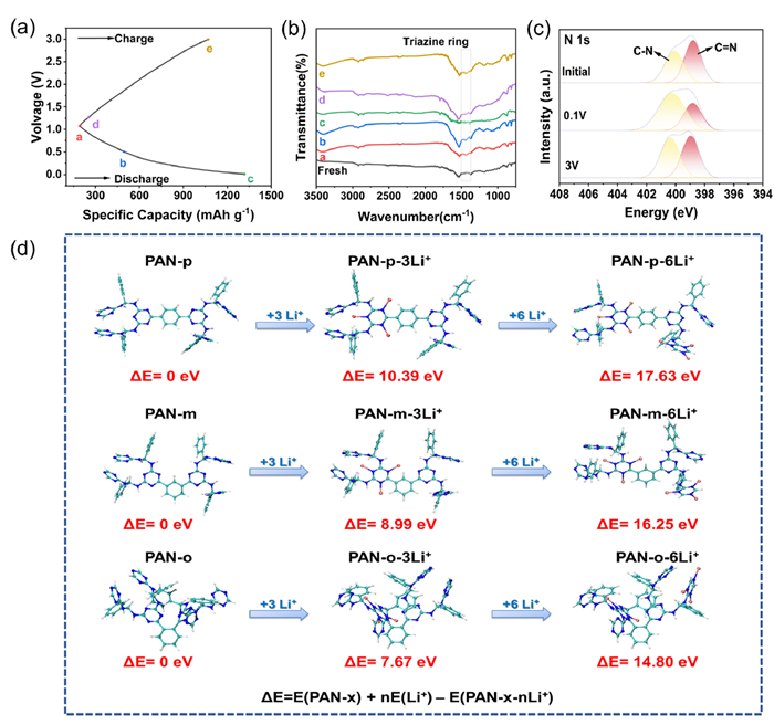
Afterward, we explore PAN-p1’s lithium storage mechanisms. As shown in Fig. S9a (Supporting information), the first CV curve of PAN-p1 exhibits a pronounced peak around 0.6 V, which can be ascribed to the formation of SEI films [39,40]. In subsequent cycles, the CV curves and reversible peaks have good overlap, indicating good reversible Li-storage processes of triazine ring. Then, ex-situ FT-IR was carried out to further study the lithium storage mechanism of PAN-p1. Figs. 5a and b show the charge-discharge curve and corresponding FT-IR spectra at different charge-discharge states. The triazine unit's characteristic peaks (1300–1500 cm−1) show reversible intensity variations during the charge/discharge processes. Similarly, the ex-situ XPS spectra reveal that the C=N peak intensity decreases along with the decreased C—N peak during discharge, and recovering during the following charge (Fig. 5c). These results demonstrate that the triazine rings serve as redox-active centers for reversible lithium storage. Further DFT calculations was carried out to better understand the Li-storage process. As shown in Fig. 5d, the optimized lithium-ion adsorption structures revealed six distinct binding sites on the triazine rings. Compared with the other two systems, the N atom on PAN-p has the strongest activity and the largest binding energy (17.63 eV), indicating its N atoms possess superior activity for Li-storage.
Figure 5
Figure 5.
(a) Charge-discharge profiles, (b) ex-situ FT-IR spectra, and (c) ex-situ XPS of PAN-p1 electrode at different voltages. (d) Theoretical calculation of the most stable Li-storage states for PAN-p, PAN-m, and PAN-o.
A systematic investigation was conducted to examine the influence of isomeric effects on electrochemical performance of PANs. The para-linked PAN-p1 exhibited superior physical and electrochemical properties relative to meta-linked PAN-m1 and ortho-linked PAN-o1. This performance stems from two key structural advantages. (1) The enhanced specific surface area and porous architecture of PAN-p1 provided abundant active sites for redox reactions. (2) The para-configuration minimizes the steric hindrance during the Li+ intercalation/deintercalation, thereby enabling high molecular reactivity and rapid redox kinetics. To validate the structure-property relationships, three polymers (PAN-p2, PAN-m2, and PAN-o2) were synthesized via condensation reactions of terephthalaldehyde with p-BzDAT, m-BzDAT, and o-BzDAT monomers, respectively (Figs. S1b and S10 in Supporting information). FT-IR and XPS confirmed the successful synthesis of target polymer structures (Figs. S10 and S11 in Supporting information). Nitrogen adsorption-desorption isotherms and TEM images were employed to analyze porosity and morphology (Fig. S12 in Supporting information). The specific surface area progressively increased from PAN-o2 (445.398 m2/g) to PAN-m2 (762.033 m2/g) and PAN-p2 (867.299 m2/g), with PAN-p2 exhibiting a predominantly mesoporous architecture. SEM images further revealed well-dispersed nanoparticles and a distinct interconnected network in PAN-p2 (Figs. S7d-f in Supporting information).
Consistent with our hypothesis, PAN-p2 exhibited superior electrochemical performance. At current densities of 0.3 and 1 A/g, PAN-p2 retained specific capacities of 260 mAh/g (500 cycles) and 240 mAh/g (800 cycles), respectively, with near-ideal Coulombic efficiency (∼100%) (Figs. S13a and c in Supporting information). Rate capability testing revealed reversible capacities of 418, 262, 187, 145, 103, and 81 mAh/g at 0.1–5 A/g, significantly outperforming PAN-m2 and PAN-o2 (Fig. S13b in Supporting information). Afterward, EIS confirmed PAN-p2’s lowest charge transfer resistance (Rct = 135.7 Ω), confirming its superior kinetics (Fig. S13d in Supporting information). Besides, b-values of PAN-p2 (0.90/0.88) delivered higher value than those of PAN-o2 (0.84/0.79) and PAN-m2 (0.87/0.84) (Figs. S14b, e and h in Supporting information), indicating its rapid capacitive behavior. The corresponding capacitive contributions increased from 54% to 72% as the scan rate rose from 0.2 mV/s to 1.0 mV/s (Figs. S14c, f and i in Supporting information). These results align with the PAN-p2’s structural advantages including superior specific surface area, optimized porosity, reduced energy barrier, and minimized steric effects, which enable high reversible capacity, exceptional rate performance, and cycling stability. Furthermore, we also confirmed the Li-storage mechanism of PAN-p2 and revealed similar electrochemical characteristics to PAN-p1 (Fig. S15 in Supporting information). The structure of materials is closely related to their electrochemical performance [41,42]. The triazine materials connected in para positions (p1, p2) exhibit a loose porous structure, while those connected in ortho positions (o1, o2) show a more aggregated morphology, which is consistent with the larger specific surface area of the para-connected materials (p1, p2). Compared to meta- (m1, m2) and ortho-connected (o1, o2) materials, para-connected materials (p1, p2) consistently demonstrate superior electrochemical performance, attributed to the reduced steric hindrance in para-connected structures that enables full exposure of active sites. The smaller band gap enhances electronic conductivity, resulting in lower impedance and faster reaction kinetics. Furthermore, different phenyl ring connection patterns also affect electrochemical performance. Specifically, at low current densities, p2, m2, and o2 exhibit lower specific capacities than p1, m1, and o1, respectively, while these differences diminish at high current densities. We hypothesize that the specific structural configuration of para-connected phenyl rings may hinder complete material activation at low currents, as evidenced by the continuously increasing capacity in Fig. S13a (Supporting information). These results further confirm the crucial role of molecular structure in determining electrochemical behavior.
In summary, we designed and synthesized six triazine-based polyamine polymers (PANs) to investigate the correlation between their chemical structures and electrochemical performance. Systematic evaluation revealed that para-linked PAN-p exhibited superior cycling stability and rate capability compared to meta- and ortho-linked counterparts. Notably, the optimized PAN-p1 electrode delivered outstanding performance, maintaining 780 mAh/g after 500 cycles at 0.3 A/g and retaining 324 mAh/g after 1000 cycles at 1 A/g without significant capacity decay. This enhanced performance originates from the minimized steric hindrance in para-connected structures, which provides: (1) Larger specific surface area, (2) well-dispersed active sites with reduced inter-molecular repulsion, and (3) facilitated Li+ insertion/extraction kinetics. This work highlights the critical role of spatial configuration in polymer design, establishing a fundamental strategy for developing high-performance polymeric electrode materials.
The authors declare that they have no known competing financial interests or personal relationships that could have appeared to influence the work reported in this paper.
Acknowledgments
The authors sincerely thank for the supports from Scientific Research Fund of Anhui Provincial Education Department (Nos. KJ2021A0002, KJ2021A0035), National Natural Science Foundation of China (No. 52203077).
Supplementary materials
Supplementary material associated with this article can be found, in the online version, at doi:10.1016/j.cclet.2025.111869.
W. Wang, S. Zhang, L. Zhang, et al., Adv. Mater. 36 (2024) 202400642. doi: 10.1002/adma.202400642
[42]
H. Li, M. Cao, R. Wang, et al., Angew. Chem. Int. Ed. 64 (2025) e202508057. doi: 10.1002/anie.202508057
Figure 1
(a) The molecular structures of PAN-p1, PAN-m1, and PAN-o1. (b) FT-IR spectra and (c) solid-state 1H NMR spectra of PAN-p1, PAN-m1, and PAN-o1. (d) The UV–vis absorption spectrum of the electrolytes after soaking the PAN-p1, PAN-m1, and PAN-o1. (e) XPS survey spectrum of PAN-p1 and corresponding high-resolution spectra of (f) C 1s and (g) N 1s.
Figure 2
TEM image of (a) PAN-p1, (b) PAN-m1, (c) PAN-o1. N2 adsorption-desorption isotherms and pore-size distribution of (d, g) PAN-p1, (e, h) PAN-m1, and (f, i) PAN-o1.
Figure 3
(a) The cycling performance of PAN-p1, PAN-m1, and PAN-o1 at 0.3 A/g. (b) The rate performance of PAN-p1, PAN-m1, and PAN-o1. (c) EIS plots of PAN-p1, PAN-m1, and PAN-o1. (d) The cycling performance of PAN-p1, PAN-m1, and PAN-o1 at 1.0 A/g. (e) Ex-situ FT-IR spectra of PAN-p1 after different cycles. (f) CV curves at different scan rates, (g) relationships between peak current and scan rates, and (h) calculated capacitive contribution for PAN-p1.
Figure 5
(a) Charge-discharge profiles, (b) ex-situ FT-IR spectra, and (c) ex-situ XPS of PAN-p1 electrode at different voltages. (d) Theoretical calculation of the most stable Li-storage states for PAN-p, PAN-m, and PAN-o.


 DownLoad:

 下载:


 下载:

