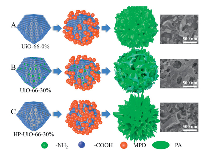
Figure 1.
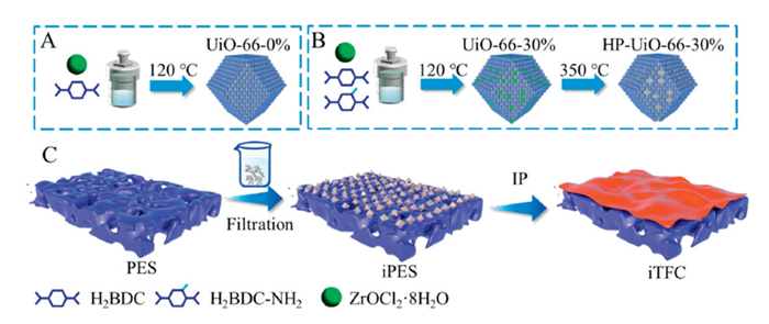
Preparation of UiO-66 and its derivatives (A, B) and fabrication process of iTFC membrane (C).
Influence of the interlayer properties on the thin-film composite membrane performance based on UiO-66 and its derivatives
Hao Liu , Pin Zhao , Yao Jiang , Subo Xu , Weilong Song , Xinhua Wang

The demand for freshwater resources has been increasing significantly, primarily due to global population growth and socioeconomic advancements that improve living standards [1,2]. The promising advancements in membrane-based technology present a viable solution to the pressing global problem of water scarcity [3–6]. The thin-film composite (TFC) membrane, which consists of an active layer formed through interfacial polymerization (IP) on a porous support layer, has emerged as the preferred choice due to its high stability and excellent separation performance [7,8]. Nevertheless, advancing TFC membranes faces challenges due to inherent trade-offs between permeability and selectivity, as well as issues related to membrane fouling. There is an urgent need for the fabrication of TFC membranes that achieve high selectivity, high water flux, and exhibit strong antifouling properties.
Recently, there has been a growing emphasis on the regulation of interlayered TFC (iTFC) membranes. These membranes are prepared by uniformly depositing nanomaterials or coatings on the support layer before the IP reaction [9–11]. Uniformly deposited interlayers on the substrate help regulate the IP reaction and facilitate the formation of a targeted polyamide (PA) layer. Until now, there have been a series of functional materials reported in the iTFC membrane fabrication, including polydopamine [12–14], polyphenols [15], titanium dioxide [16], carbon nanotubes [16–18], graphene oxide [19,20], MXene [21,22], covalent organic frameworks [23–25]. Among them, metal–organic frameworks (MOFs), crystal coordination polymers composed of organic ligands connecting to metal ions or clusters, have gained great popularity in the field of membrane design and fabrication due to the mild preparation conditions, high surface area, adjustable chemical functions and high compatibility between organic ligands and polymers [26].
Moreover, MOFs exhibit great flexibility in the structure and design of properties [27]. By modifying the types of organic ligands, a variety of MOFs can be tailored for different practical applications in iTFC membranes [28–30]. Until now, many MOFs have been selected as the interlayer to fabricate the iTFC membrane. For instance, UiO-66 coupled with polydopamine and polyethyleneimine [31], HKUST-1 [32] and poly(sodium 4-styrenesulfonate) modified ZIF-8 [33] were applied in TFC membrane modification as an interlayer. The introduction of an interlayer would provide a novel interface with a uniform porosity and moderate hydrophilicity, affect the absorption and release of the reactive monomer, and then regulate the generation of PA layer [32,34,35]. Moreover, the addition of the interlayer would offer an additional transport pathway, thus leading to an enhanced membrane performance [14]. Different interlayers possess various properties, such as functional groups, pore size, and porosity, which influence the TFC membrane performance in different ways. As indicated in the literature, the amine functionalization enhanced the stability of membrane, attributed to the efficient covalent bonding between the -NH2 groups and the acyl chloride groups [29]. However, the influence of the interlayer properties on PA morphology and membrane performance is still unclear, and the regulatory mechanism of interlayer on IP reaction is not fully understood.
In this work, Zr-based MOFs (UiO-66) were selected as the representative material due to their strong water stability, high adjustability, and ease of operation [36]. UiO-66 with varying amino group densities and pore sizes was synthesized through fine-tuning the composition and ratios of ligands and thermal treatment. First, UiO-66 nanomaterial with varying hydrophilicity and pore sizes was incorporated into the TFC membrane as an interlayer to investigate its impact on the IP reaction. The comprehensive investigation was focused on assessing the impact of incorporating the UiO-66 interlayer on both the morphology and physicochemical properties of the PA layer. Moreover, membrane performance was rigorously evaluated using a forward osmosis (FO) platform. Furthermore, the potential mechanism of the series of UiO-66 interlayers on the PA layer regulation was analyzed with the assistance of the diffusion rate of m-phenylenediamine (MPD). This study shifts focus from traditional frameworks by investigating the dynamic evolution the dynamic evolution of functional groups and their regulatory mechanism in the IP process. More importantly, within the homologous Zr-based MOFs material system, we achieve precise control over the ligand exchange strategy to directly modulate the MOFs pore size. This work systematically reveals the critical role of the nanoconfinement effect during the TFC membrane formation process. By exploring the regulation of functional groups and pore structures on the IP reaction, this study establishes a quantitative structure-activity relationship between the physicochemical properties of MOF interlayers and the kinetics of the IP reaction.
UiO-66, UiO-66–30% (30%, the ligand mass ratio of 2-aminoterephthalic acid (H2BDC–NH2) to the total), and hierarchically porous UiO-66 (HP-UiO-66–30%), which contains more mesopores, were synthesized following established methods (Figs. 1A and B) [37].
The fabrication process of iTFC membrane is illustrated in Fig. 1C. Initially, UiO-66 and its derivatives were deposited onto a polyethersulfone (PES) substrate via filtration. The good dispersion of UiO-66 and its derivatives at 100 mg/L was prepared by dissolving the corresponding powders in ethanol under the assistance of ultrasonic treatment. The interlayer loading was controlled by adjusting the volume of the suspension filtered. The resulting substrates were designated as iPES-x, where x represents the mass of UiO-66 incorporated (0, 0.01, 0.02, 0.04, 0.06 and 0.08 µg/mm2). Similarly, the substrates with UiO-66–30% and HP-UiO-66–30% interlayer at 0.04 µg/mm2 were named as NH2-iPES-0.04 and HP-iPES-0.04. The PA layer was subsequently formed through a conventional IP reaction, which has been extensively discussed in our previous publications [38–40]. The membranes prepared with different UiO-66 loading (0.01, 0.04, 0.06 and 0.08 µg/mm2) were named to be iTFC-x (x represents the interlayer loading mass). Additionally, the membrane with UiO-66–30% at 0.04 µg/mm2 was named to be NH2-iTFC-0.04, while the membrane with HP-UiO-66–30% at 0.04 µg/mm2 was named to be HP-iTFC-0.04. The details of the characterization methods are further provided in the materials and methods in Supporting information.
Membrane performance and fouling experiments were evaluated using a lab-scale FO system (Fig. S1 in Supporting information). The membrane performance was evaluated based on water flux (Jw), reverse salt flux (Js), and the ratio of Js and Jw (Js/Jw, g/L). Fouling experiments were performed in the same cross-flow system described above using 200 mg/L sodium alginate (SA) as FS. Additional details can be found in our previous work and the figure legends of Fig. S1 [38,41].
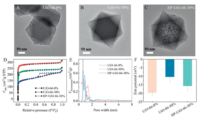
The morphology of UiO-66 and its derivatives was elucidated through transmission electron microscope (TEM) measurement. As described in Figs. 2A-C and Figs. S2A-C (Supporting information), UiO-66–0%, UiO-66–30% and HP-UiO-66–30% all had a regular crystal structure with similar size (~200 nm). However, unlike the solid construction of UiO-66–0% and UiO-66–30%, HP-UiO-66–30% contained numerous internal mesopores, mainly due to the thermal decomposition of NH2-BDC [37]. The corresponding X-ray diffraction (XRD) patterns (Fig. S2D in Supporting information) also demonstrated that all UiO-66 based derivatives retained good crystallinity, in which the peak at 7.4° and 8.5° was separately attributed to the crystal plane (111) and (200), well matching with the simulated one (CCDC, 837, 796). The presence of peaks at 774, 675, and 555 cm−1 in the spectrum (Fig. S2E in Supporting information) was associated with C–H and Zr-O [37]. The BDC molecule, has a carboxylic acid group with C–O bonds, which was characterized by prominent peaks at 1397 cm−1 and 1585 cm−1 [37]. As illustrated in Fig. 2D, the N2 adsorption-desorption isotherm transitions from type Ⅰ to type Ⅳ, indicating a change in the pore structure. With the introduction of NH2-BDC, there was a reduction in micropore volume, primarily attributed to capillary condensation induced by mesopores. In addition, the pore size distributions revealed an increase in mesopores with the introduction of H2BDC–NH2. HP-UiO-66–30% had a large diameter pore size ranging from 2 nm to 8 nm (Fig. 2E). These findings indicated that the presence of NH2-BDC led to the partial structural collapse of the MOFs after thermal decomposition, thereby increasing the number of mesopores. Finally, the variations in charge values of UiO-66 and its derivatives were attributed to differences in the amino and carboxyl group ratios during material synthesis (Fig. 2F). The presence of -COOH in BDC resulted in UiO-66–0% exhibiting the most pronounced negative potential, whereas the incorporation of -NH2 in NH2-BDC reduced the negative charge of UiO-66–30%. The enhanced negative charge observed in HP-UiO-66–30% was mainly due to the decomposition of NH2-BDC during thermal decomposition. Meanwhile, the reduction in the total number of ligands slightly decreased its negative charge compared to UiO-66–0%.
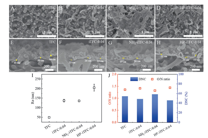
Conventional IP was performed on pristine and UiO-66-coated PES substrates (Figs. S3A-D and S4A-C in Supporting information) to fabricate TFC and iTFC membranes. All membranes displayed characteristic leaf-like and nodular PA morphologies (Fig. 3 and Fig. S5 in Supporting information), with enhanced leaf-like structure density observed in UiO-66-interlayered membranes. To systematically probe structure-property relationships, UiO-66 was functionalized via -NH2 incorporation and mesopore size expansion. Characterization revealed comparable PA morphologies between iTFC-0.04 and HP-iTFC-0.04, whereas NH2-iTFC-0.04 exhibited a smoother surface with a distinctive double-layer structure absent in other variants (Fig. 3C). Cross-sectional scanning electron microscope (SEM) analysis (Figs. 3E-H) confirmed that UiO-66 interlayers reduced the PA layer intrinsic thickness near the substrate interface. AFM characterization further quantitatively determined that the introduction of UiO-66–0% interlayer increased the membrane roughness with the Ra value increasing from 49.43 nm of TFC to 69.53–137.00 nm of iTFC (Figs. S5I and S6A-D in Supporting information). While NH2-iTFC-0.04 has comparable roughness to iTFC-0.04, HP-iTFC-0.04 showed significantly elevated roughness of 205 nm (Fig. 3I).
MPD diffusion experiments (Fig. S7 in Supporting information) revealed that UiO-66 enhanced MPD migration to the oil-water interface, exhibiting higher initial diffusion intensity than the control. The electrostatic adsorption of MPD on MOF surfaces established localized concentration gradients near the interface, with enhanced negative charges amplifying MPD attraction and the hydrophobic interface suppressing aqueous phase retention, synergistically improving monomer transport efficiency. This charge-mediated diffusion, coupled with the interlayer's mesoporous structure (notably in HP-UiO-66–30%), facilitated sustained high diffusion rates and intensified IP dynamics, ultimately promoting a rougher PA morphology. Under these conditions, the enhanced initial reaction intensity of IP promoted the formation of a dense PA layer, which subsequently restricted the further diffusion of amine monomers. This diffusion limitation will create favorable conditions for the development of a thin PA layer [42,43].
Based on X-ray photoelectron spectroscopy (XPS) scanning results, DNC of PA layer was exhibited in Fig. S5J (Supporting information). The O/N ratio slightly increased with the increase in interlayer loading, indicating that the introduction of the interlayer slightly reduced the DNC of the PA layer. At the same time, the interlayer with HP-UiO-66–30% weakened the DNC. However, an introduction of -NH2 may slightly enhanced the DNC of the PA layer as shown in Fig. 3J. Furthermore, the inverse correlation between DNC and -COOH density aligns precisely with the zeta potential evolution pattern shown in Fig. S8E (Supporting information). The significantly elevated zeta potential in NH2-iTFC underscored the predominance of interlayer charge regulation mechanisms. Moreover, the results of ATR-FTIR spectra indicated the successful synthesis of all membranes (Figs. S5K and S8D in Supporting information).
Compared to the control TFC membrane, significant changes in membrane performance were observed when UiO-66–0% was incorporated as an interlayer (Figs. 4A and B). In active layer facing feed solution side (AL-FS) mode, water permeability gradually increased, reaching a plateau at an interlayer loading of 0.04 µg/mm2. While membranes iTFC-0.06 and iTFC-0.08 exhibited significantly higher water flux, they also showed a corresponding increase in reverse salt flux. As shown in Fig. 4B, similar trends were observed in active layer facing draw solution side (AL-DS) mode. Overall, the content of the 0.04 µg/mm2 interlayer enabled the iTFC membrane to achieve the optimal specific salt flux. Therefore, this loading was selected for subsequent study of UiO-66 series materials.
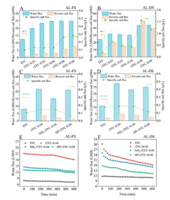
Compared to the TFC membrane (7.98 L m−2 h−1 (LMH), 1.23 g m−2 h−1 (gMH)), the iTFC membrane with a UiO-66–0% interlayer demonstrated a significant increase in water flux, albeit with an elevated reverse salt flux. The optimal performance was observed at a UiO-66–0% loading of 0.04 µg/mm², achieving a water flux of 24.83 LMH and a reverse salt flux of 3.11 gMH. The introduction of the interlayer reduced the effective water transport path length, thereby enhancing permeability. However, it also resulted in a decrease in the PA DNC, which led to a reduction in rejection efficiency, a trend that aligns with previous studies [44]. The UiO-66–30% and HP-UiO-66–30% were further incorporated as interlayer modified materials in the preparation of iTFC membranes. Compared to iTFC-0.04 (21.67 LMH, 3.69 gMH), NH2-iTFC-0.04 had a reduced water flux (15.13 LMH). The performance is depicted in Figs. 4C and D. The UiO-66–30% increased CO2 generation, leading to the formation of the large leaf-like structure (Fig. S8A in Supporting information). Compared to iTFC-0.04, the overgrown large leaf-like structures in the PA layer of NH2-iTFC-0.04 limited the further increase of the effective contact area, which subsequently decreased membrane permeability. HP-iTFC-0.04 exhibited high water flux (21.04 LMH) while maintaining the lowest reverse salt flux (1.39 gMH). The high porosity of HP-UiO-66–30% enhanced its affinity with PA, improving the rejection while maintaining high water permeability. Furthermore, the anti-fouling capacity of iTFC-0.04, NH2-iTFC-0.04, and HP-iTFC-0.04 has been evaluated in AL-FS mode. The results indicated that the performance of all iTFC membranes remained stable and reliable (Figs. 4E and F), even under exposure to organic foulants. The iTFC membranes consistently demonstrated superior water permeation performance throughout the entire 10-h test duration, in comparison to the control group. Although the contact angle and surface roughness of the iTFC membrane were increased, its flux superiority remained preserved. This phenomenon may originate from the nanoscale surface roughness, which optimizes hydrodynamic boundary layer dynamics and promotes the formation of loosely adherent foulant layers during FO [44]. Additionally, the performance of the fabricated membrane has been compared with that of FO membranes incorporating an interlayer, as reported in previous literature, and is presented in Table S1 (Supporting information). Compared with the conventional interlayer materials, the UiO-66 nanoparticle layer significantly enhanced water permeability in this work. The exceptional efficacy of the iTFC membrane employing the UiO-66 interlayer can be attributed to the synergistic integration of a thin, highly selective PA layer with an excellent separation efficiency and a nanoparticle layer composed of UiO-66, which offers superior water permeability. The enhancement of surface leaf morphology resulted in an amelioration of water permeability in the iTFC membrane. The crucial point is that there was no substantial alteration in rejection performance despite the increased water flux. In terms of the membrane performance evaluation parameter Js/Jw, HP-UiO-66–30% demonstrated a notable advantage compared to Yi Wang et al.'s study with a Js/Jw value of 0.27 g/L [45]. The performance of the prepared iTFC membrane remained consistently stable throughout a long-term experiment lasting over 20 h, even after being stored in DI water for more than two weeks, indicating exceptional membrane stability (Fig. S9 in Supporting information).
The introduction of UiO-66–0% modified the characteristics of the IP reaction interface. First, the presence of MOF particles increased the surface roughness of the substrate (Figs. S4 and S6E-H in Supporting information), providing a textured interface for PA layer growth. Second, the incorporation of MOF material regulated the release of MPD during the IP process. MPD release experiments (Fig. S7 in Supporting information) confirmed that UiO-66–0% accelerated initial MPD diffusion rates, corroborating previous reports [46]. The experimental results (Fig. S7) also showed that UiO-66–0% and UiO-66–30% had similar effects on the initial MPD concentration (Figs. 5A and B), while HP-UiO-66–30% significantly increased the initial MPD concentration (Fig. 5C). The modification of the reaction interface laid the foundation for rough morphology formation in PA, ultimately promoting the development of the thin layer and rough structure, which improved water permeability.
Furthermore, the incorporation of different functional groups as interlayer materials played a crucial role in regulating the IP reaction. In this study, we observed some flat regions on the top surface of NH2-iTFC membrane, accompanied by small nodular structures beneath these regions (Fig. 5B). This phenomenon may be attributed to the excessive growth of interconnected belt-like features. Previous literature also has demonstrated that nano-bubbles acted as catalysts during the IP process, leading to the emergence of this unique morphology [47–49]. Therefore, it is postulated that the incorporation of UiO-66–30% facilitated the release of CO2 during the IP reaction, which in turn resulted in the formation of this particular morphology (Fig. 5B). To clarify this process, we have provided a membrane formation diagram under the influence of various nanoparticles (Fig. 5). The primary distinction between nanoparticles in Figs. 5A and B lies in the variation of -NH2 and -COOH functional groups. Although their impact on the initial MPD concentration was minimal, the presence of -NH2 promoted the formation of a double-layer structure (highlighted in green in Fig. 5B). This study experimentally confirmed that functional groups can exert significant regulatory effects on the IP process. However, the quantitative control of IP reaction progression remains to be fully understood. Future research should focus on developing methodologies to achieve precise modulation over the IP reaction.
In this study, HP-iTFC-0.04 showed a high-level water permeability and a very low reverse salt flux (Figs. 4C and D). The high performance of HP-iTFC-0.04 can be primarily attributed to two key factors. First, the initial release intensity of MPD exhibited a noticeable increase (Fig. S7), which corresponds to the red spheres observed on the surface of HP-UiO-66–30% in Fig. 5C. The accelerated release of MPD facilitated the development of a nanoscale roughened surface topography (visualized as green domains in Fig. 5C), thereby significantly enhancing the effective filtration surface area. Furthermore, the hierarchically porous structure of HP-UiO-66–30% (Fig. 2E) served dual functions: (1) Its optimized mesopore network enabled efficient monomer storage and controlled interfacial transport of MPD, and (2) the enhanced structural compatibility between the interlayer and PA matrix effectively suppresses defect formation. However, an excessively rough surface topography might not provide any advantages when it comes to fouling resistance. Therefore, to explore the optimal conditions for achieving the desired morphology of PA, further modifications are necessary to improve the mesoporous properties of HP-UiO-66–30%. In practical applications, the pore distribution of the interlayer should be dynamically tailored based on target water quality parameters (e.g., ionic strength, types of pollutants) to achieve optimal performance.
This work systematically investigated the regulatory mechanisms of interlayer characteristics derived from UiO-66 nanomaterials on membrane performance. By incorporating a uniformly coated UiO-66 interlayer, the iTFC membrane formed an ultra-thin PA layer with extensive leaf-like morphology. While demonstrating high water permeability (21.67 LMH), it exhibited an elevated reverse salt flux (3.11 gMH). Moreover, the introduction of the amino functional group (UiO-66–30%) led to excessive growth of leaf-like structures at the top of PA layer. The double-layer structure reduced the water flux to 15.13 LMH. Furthermore, the interlayer based on HP-UiO-66–30%, with a finely tuned porosity, not only enhanced the initial release intensity of the monomer MPD but also minimized PA defects due to increased mesoporous structures. This modification resulted in overcoming the traditional trade-off between permeation (water flux of 21.04 LMH) and selectivity (reverse salt flux of 1.39 gMH). These results underscore the feasibility of tailoring interlayer properties to optimize PA layer characteristics, achieving TFC membranes with simultaneously enhanced permeability and selectivity. Moreover, the intrinsic functional groups and engineered porosity of MOFs exhibit universal adaptability in regulating IP reactions, advancing mechanistic insights into nanomaterial-mediated control of IP dynamics. However, it is essential to further optimize the dispersion of nanomaterials and IP techniques to reduce production costs. Additionally, long-term operational tests should be conducted to systematically evaluate the performance and stability of the membrane when treating real wastewater.
The authors declare that they have no known competing financial interests or personal relationships that could have appeared to influence the work reported in this paper
Hao Liu: Writing – original draft, Visualization, Validation, Supervision, Software, Project administration, Methodology, Funding acquisition, Formal analysis, Data curation, Conceptualization. Pin Zhao: Writing – review & editing, Supervision, Resources, Project administration, Methodology, Conceptualization. Yao Jiang: Validation. Subo Xu: Validation. Weilong Song: Supervision. Xinhua Wang: Supervision, Resources, Project administration.
This work was supported by the National Natural Science Foundation of China (Nos. 52100089, 51978312, and 42307487).
Supplementary material associated with this article can be found, in the online version, at doi:
M.M. Mekonnen, A.Y. Hoekstra, Sci. Adv. 2 (2016) e1500323. doi: 10.1126/sciadv.1500323
R. Xu, J. Zhang, Y. Kang, et al., Environ. Sci. Technol. 58 (2024) 6835–6842. doi: 10.1021/acs.est.3c10497
D.S. Sholl, R.P. Lively, Nature 532 (2016) 435–437. doi: 10.1038/532435a
L. Fei, C. Chen, L. Shen, et al., Chem. Eng. J. 460 (2023) 141694. doi: 10.1016/j.cej.2023.141694
B. Wang, L. Shen, J. Xu, et al., Sep. Purif. Technol. 356 (2025) 129928. doi: 10.1016/j.seppur.2024.129928
T. Bai, K. Zhao, Z. Lu, et al., Chin. Chem. Lett. 32 (2021) 1051–1054. doi: 10.1016/j.cclet.2020.07.034
Z. Zhang, J. Hu, S. Liu, et al., Chin. Chem. Lett. 32 (2021) 2882–2886. doi: 10.1016/j.cclet.2021.03.028
C.Y. Tang, Y.N. Kwon, J.O. Leckie, Desalination 242 (2009) 149–167. doi: 10.1016/j.desal.2008.04.003
J. Wang, L. Wang, M. He, et al., RSC Adv. 12 (2022) 34245–34267. doi: 10.1039/d2ra06304b
Z. Yang, P.F. Sun, X. Li, et al., Environ. Sci. Technol. 54 (2020) 15563–15583. doi: 10.1021/acs.est.0c05377
H. Li, X. Li, G. Ouyang, et al., J. Environ. Sci. 141 (2024) 182–193. doi: 10.70114/acmsr.2024.1.1.p182
B. Li, X.X. Ke, Z.H. Yuan, et al., Desalination 534 (2022) 115781. doi: 10.1016/j.desal.2022.115781
Y. Huang, H. Jin, H. Li, P. Yu, Y. Luo, RSC Adv. 5 (2015) 106113–106121. doi: 10.1039/C5RA20499B
Z. Yang, F. Wang, H. Guo, et al., Environ. Sci. Technol. 54 (2020) 11611–11621. doi: 10.1021/acs.est.0c03589
X. Zhang, Y. Lv, H.C. Yang, Y. Du, Z.K. Xu, ACS Appl. Mater. 8 (2016) 32512–32519. doi: 10.1021/acsami.6b10693
M. Zhang, W. Jin, F. Yang, et al., Environ. Sci. Technol. 54 (2020) 7715–7724. doi: 10.1021/acs.est.0c02809
Z. Zhou, Y. Hu, C. Boo, et al., Environ. Sci. Technol. Lett. 5 (2018) 243–248. doi: 10.1021/acs.estlett.8b00169
M.J. Park, C. Wang, D.H. Seo, et al., J. Membr. Sci. 620 (2021) 118901. doi: 10.1016/j.memsci.2020.118901
X.J. Song, Y.J. Zhang, H.M. Abdel-Ghafar, et al., Chem. Eng. J. 412 (2021) 128607. doi: 10.1016/j.cej.2021.128607
L. Tian, Y. Jiang, S. Li, L. Han, B. Su, Sep. Purif. Technol. 248 (2020) 117153. doi: 10.1016/j.seppur.2020.117153
X. Wu, M. Ding, H. Xu, et al., ACS Nano 14 (2020) 9125–9135. doi: 10.1021/acsnano.0c04471
D. Xu, X. Zhu, X. Luo, et al., Environ. Sci. Technol. 55 (2021) 1270–1278. doi: 10.1021/acs.est.0c06835
S. Han, Z. Mai, Z. Wang, et al., ACS Appl. Mater. 14 (2022) 3427–3436. doi: 10.1021/acsami.1c19605
Y. He, X. Lin, J. Chen, H. Zhan, J. Membr. Sci. 635 (2021) 119476. doi: 10.1016/j.memsci.2021.119476
C. Li, S. Li, J. Zhang, et al., J. Membr. Sci. 604 (2020) 118065. doi: 10.1016/j.memsci.2020.118065
M. Kattula, K. Ponnuru, L. Zhu, et al., Sci. Rep. 5 (2015) 15016. doi: 10.1038/srep15016
L. Fei, L. Shen, C. Chen, et al., Small 20 (2024) e2306528. doi: 10.1002/smll.202306528
S. Cao, A. Deshmukh, L. Wang, et al., Environ. Sci. Technol. 56 (2022) 8807–8818. doi: 10.1021/acs.est.2c00551
Y. Wen, X. Zhang, X. Li, Z. Wang, C.Y. Tang, ACS Appl. Nano Mater. 3 (2020) 9238–9248. doi: 10.1021/acsanm.0c01860
D.L. Zhao, W.S. Yeung, Q. Zhao, T.S. Chung, J. Membr. Sci. 604 (2020) 118039. doi: 10.1016/j.memsci.2020.118039
W. Zhao, X. Zhang, C. Li, et al., ACS Appl. Nano Mater. 6 (2023) 6901–6910. doi: 10.1021/acsanm.3c00619
K. Chen, P. Li, H. Zhang, et al., Sep. Purif. Technol. 251 (2020) 117387. doi: 10.1016/j.seppur.2020.117387
B. Zhao, Z. Guo, H. Wang, et al., J. Membr. Sci. 625 (2021) 119154. doi: 10.1016/j.memsci.2021.119154
S. Yang, H. Li, X. Zhang, et al., J. Membr. Sci. 614 (2020) 118433. doi: 10.1016/j.memsci.2020.118433
Z. Wang, Z. Wang, S. Lin, et al., Nat. Commun. 9 (2018) 2004. doi: 10.1038/s41467-018-04467-3
S. Xu, Q. Gao, C. Zhou, et al., Mater. Chem. Phys. 274 (2021) 125182. doi: 10.1016/j.matchemphys.2021.125182
R. Xu, Q. Ji, P. Zhao, et al., J. Mater. Chem. A 8 (2020) 7870–7879. doi: 10.1039/c9ta13747e
Q. Zhou, P. Zhao, R. Xu, et al., J. Membr. Sci. 661 (2022) 120942. doi: 10.1016/j.memsci.2022.120942
M. Xu, P. Zhao, C.Y. Tang, X. Yi, X. Wang, Chin. Chem. Lett. 33 (2022) 3818–3822.
Y. Hu, P. Zhao, H. Liu, et al., Chin. Chem. Lett. 34 (2023) 107931. doi: 10.1016/j.cclet.2022.107931
Y. Jiang, P. Zhao, S. Xu, et al., Desalination 585 (2024) 117753. doi: 10.1016/j.desal.2024.117753
Y. Wen, R. Dai, X. Li, et al., Sci. Adv. 8 (2021) eabm4149.
Y. Shi, Z. Mai, Q. Shen, et al., J. Membr. Sci. 702 (2024) 122804.
S. Xu, P. Zhao, H. Liu, et al., Environ. Sci. Technol. 59 (2024) 902–912.
Y. Wang, X. Li, S. Zhao, et al., Ind. Eng. Chem. Res. 58 (2018) 195–206.
H. Liu, B. Li, P. Zhao, et al., Chin. Chem. Lett. 34 (2023) 108369.
X.H. Ma, Z.K. Yao, Z. Yang, et al., Environ. Sci. Technol. Lett. 5 (2018) 123–130. doi: 10.1021/acs.estlett.8b00016
X. Ma, Z. Yang, Z. Yao, et al., J. Colloid Interface Sci. 540 (2019) 382–388.
Z. Qiu, H. Han, T. Wang, R. Dai, Z. Wang, Desalination 552 (2023) 116457.

Figure 1 Preparation of UiO-66 and its derivatives (A, B) and fabrication process of iTFC membrane (C).

Figure 2 Chemical characterizations of UiO-66 and its derivatives. (A-C) TEM images. (D) N2 adsorption-desorption isotherm curves. (E) Pore size distributions. (F) Zeta potential. The pH values of the dispersions for UiO-66–0%, UiO-66–30%, and HP-UiO-66–30% were measured as 8.08, 8.26, and 8.19, respectively.

Figure 3 Chemical characterizations of membranes. (A-D) PA surface morphology. (E-H) TFC/iTFC cross-sectional morphology. (I) Surface roughness. (J) The O/N ratio and the degree of crosslinking (DNC).

Figure 4 Membrane separation properties of UiO-66–0% interlayered iTFC with varying loadings in the (A) AL-FS and (B) AL-DS mode. Membrane performance of UiO-66 series interlayered iTFC membranes. (C) Membrane performance in the AL-FS mode. (D) Membrane performance in the AL-DS mode. Water flux of fouling experiment in the (E) AL-FS and (F) AL-DS mode.

 扫一扫看文章

扫一扫关注我们
 DownLoad:
 下载:
下载:

 下载:
下载: