Citation:
Yan Qiao, Yanan Wang, Mengfan Li, Dun Li, Wenchuan Lai, Hongwen Huang. Mitigating the carbonate issues in electrochemical CO2 reduction: Fundamental understanding and design strategies[J]. Chinese Chemical Letters,
2026, 37(5): 111861.
doi:
10.1016/j.cclet.2025.111861
Mitigating the carbonate issues in electrochemical CO2 reduction: Fundamental understanding and design strategies
English
Mitigating the carbonate issues in electrochemical CO2 reduction: Fundamental understanding and design strategies
College of Materials Science and Engineering, Hunan University, Changsha 410082, China
b.
College of Chemistry and Materials Science, Nanjing Normal University, Nanjing 210023, China
c.
Key Laboratory of Mesoscopic Chemistry of MOE and Jiangsu Provincial Lab for Nanotechnology, School of Chemistry and Chemical Engineering, Nanjing University, Nanjing 210023, China
d.
Shenzhen Research Institute of Hunan University, Shenzhen 518055, China
Received Date:
05 March 2025 Accepted Date:
17 September 2025 Revised Date:
14 July 2025 Available Online:
15 May 2026
Abstract:
The electrochemical CO2 reduction (CO2R) holds the potential to manufacture carbon-based chemicals and fuels while advancing toward carbon neutrality. On the path to achieving practical CO2R, a significant challenge lies in the formation of carbonate salts due to the interplay between CO2, local alkalinity and metal cations. The carbonate issue leads to the wastage of CO2 reactant, thus resulting in low carbon utilization efficiency and high costs for carbonate regeneration. Additionally, such salt formation can threaten the operation stability of the CO2R in electrolyzers equipped with gas diffusion electrodes (GDE). These challenges motivate us to conduct the present review, aiming to provide a comprehensive understanding and propose solution strategies for the carbonate problem. We start from the mechanism insights into carbonate formation with specific analysis on the kinetics of carbonate formation, mass transfer process, and the influence of interfacial pH, followed by the exposition of advanced techniques to monitor the carbonate accumulation. Next, the design strategies to solve the carbonate problem including the optimization of electrolyte, electrode, membranes and operation conditions, are presented, with a highlight on acidic CO2 electrolysis system without introducing metal cations into electrolyte systems. We finally end up by offering future opportunities in this evolving field. These timely and inspiring perspectives can guide researchers in addressing carbonate-related issues and advance CO2R toward practical feasibility.
Electrochemical CO2 reduction (CO2R) offers a promising zero-emission alternative for mitigating the greenhouse effect and producing valuable chemicals and fuels, thereby contributing to carbon neutrality [1-4]. It also holds significant potential to reduce dependence on fossil fuels, with the availability of low-cost renewable electricity further enhancing the feasibility of scaling the CO2R technology to power modern civilization [5-9]. To improve the efficiency of CO2R, primary efforts involve the design of high-performance catalysts and development of powerful electrolysis systems, which encompass the design of gas diffusion electrodes, novel polymer electrolyte membranes and electrolysis reactors [10-18]. In the beginning, CO2R was predominantly performed in conventional H-cells, where CO2 is fed into aqueous electrolyte. This setup has been widely used for catalyst screening and mechanistic studies. However, the low solubility of CO2 in aqueous solution (~33 mmol/L at 25 ℃) results in low current density, typically below 50 mA/cm2 [2,19,20]. To overcome the limitations of mass transfer of CO2 in H-cells, flow cells based on gas diffusion electrodes (GDEs) have been recently popularized. This innovation enables much higher current densities by alleviating mass transfer limitations of CO2 onto catalyst surfaces in flow cells [21-24], with the current density surpassing several hundred mA/cm2 or even 1 A/cm2, which can meet the requirement for industrial application (> 100 mA/cm2) [25]. Another advancement is the implementation of membrane electrode assembly (MEA) that eliminates the catholyte between the membrane and GDE. The ohmic loss is reduced on account of a shorter cathode-anode distance compared to that in flow cell. The MEA enables researchers to achieve high current densities at lower cell voltages, resulting in higher energy efficiency [26,27]. Despite significant progress in achieving high selectivity and large current densities in GDE-based CO2R [28], the "alkalinity problem" associated with carbonate formation and salt precipitation markedly lowers the system efficiency and operation stability, hindering the commercialization of CO2R technology [29,30].
Alkaline or neutral electrolytes are now typically utilized in flow cells or MEA. This choice is primarily made due to the consensus that a high electrolyte pH can suppress the competing hydrogen evolution reaction (HER) and facilitate the C–C coupling. Unfortunately, in alkaline medium, the input CO2 spontaneously reacts with OH− species in electrolyte to form numerous carbonate ions [31,32]. Even in neutral electrolytes, carbonate ions can still be formed through reactions between CO2 and in situ OH− under reaction conditions that consume protons and create local alkalinity. The formation of carbonate ions significantly wastes the CO2 reactant and reduces the single-pass carbon efficiency (SPCE) of CO2R. On the one hand, quantitative analysis reveals that 95% of the input CO2 is lost in alkaline electrolyte due to carbonate formation and subsequent crossover through anion exchange membranes (75%, in neutral electrolyte). Moreover, the carbonates also dramatically increase the energy consumption of CO2R to recover CO2 from the carbonate ions. The energy stored in CO2R products is usually estimated to be 100–130 kJ/mol electrons, while carbonate regeneration into CO2 requires over 230 kJ/mol. A calculation model proposed by Sinton et al. shows that carbonate regeneration accounts for approximately 60%−70% of the total energy cost in a CO2 electrolysis-to-C2H4 process [33,34]. On the other hand, alkali metal cations (e.g., K+) are essential in most CO2R processes for inhibiting the undesired HER and promoting the kinetics of CO2 reduction [35]. However, the continuous build-up of metal cations and (bi)carbonate ions at the electrode surface can ultimately lead to the precipitation of (bi)carbonate salts once their solubility limits are exceeded [36]. The carbonate precipitation on or within the GDE poses a big threat to the operational stability of CO2R in flow cells or MEA, as it obstructs the transport of CO2 gases through the pore channels and increases the risk of flooding [37,38]. Therefore, addressing these carbonate-related challenges is crucial for improving the practicality of CO2R.
The increasing interest in CO2R has spurred researchers to explore various strategies for mitigating carbonate-related challenges. However, there is still a lack of clear understanding of the carbonate formation mechanism and a comprehensive overview of prevention strategies. This review aims to fill this gap by providing a timely summary of recent progress in addressing carbonate issues. We first present insights into the mechanisms of carbonate formation, including specific analysis of the influence of reaction equilibrium, mass transport and phase separation. This is followed by an introduction to advanced techniques for monitoring the formation and precipitation of carbonate salts. The main section of the review focuses on different strategies for preventing the formation of carbonate salts or eliminating them. Effectively addressing the carbonate challenge requires integrated approaches involving electrolyte engineering, electrode design, optimization of electrolysis conditions, and upgrading of electrolysis modes. Finally, we highlight future opportunities to resolve these issues, aiming to advance CO2R towards practical applications and commercialization.
2.
Mechanisms of carbonate formation and their impacts
Although numerous studies have focused on electrode engineering and catalyst design−particularly the adoption of gas diffusion electrodes (GDEs) to facilitate proton and electron transfer for efficient product formation, the CO2R field still faces significant challenges [39,40]. These challenges include minimizing CO2 loss and mitigating the energy penalties associated with salt precipitation [41]. Salt precipitation is particularly common in alkaline flow cells and MEA electrolyzers, where it involves reactions between CO2 gas, hydroxide ions (OH−) produced during CO2R or the original OH− in the bulk electrolyte, and cations accumulated near the cathode [42,43]. To better understand the mechanisms of carbonate formation, this section highlights three critical factors: the kinetics of carbonate formation, mass transfer process, and the influence of interfacial pH. Understanding these effects, which relate to supersaturation, precipitation, diffusion and salt growth, is crucial for developing effective strategies to mitigate carbonate-related issues.
2.1
Kinetics of carbonate formation
The kinetics of carbonate formation are critical to understanding the challenges associated with CO2R. In alkaline or neutral electrolytes, CO2 reacts with other species to form carbonates via specific pathways, and the rates of these reactions directly influence both electrocatalytic efficiency and system stability. For example, during carbon dioxide (CO2) electrolysis, electroreduction of CO2-to-CO occurs on an Au nanocatalyst in 1 mol/L KOH environment. When CO2 gas was fed into the gas chamber, cathode reactions are as follows:
CO2+H2O+e−→CO+2OH−
(1)
2H2O+e−→H2+2OH−
(2)
During practical electrolysis, the interfacial pH near cathode is relatively high, owing to the formation of OH- from the cathode reactions with high current [44]. When one CO2 molecule is converted, two hydroxide ions are formed in alkaline or neutral electrolyte. The hydroxide ions are rapidly consumed by exergonic bicarbonate species production as it reacts with CO2 in cathode, as shown in the following equations:
CO2+OH−↔HCO3−
(3)
(pKa = 7.8*, * means a CO2 partial pressure of 1 bar in 1 mol/L HCO3-)
HCO3−+OH−↔CO32−+H2O(pKa=10.3)
(4)
The formation kinetics of these (bi)carbonates are strongly driven by the local OH- concentration and pH, resulting in rapid carbonate accumulation near the cathode surface. Additionally, owing to the widespread presence of metal cations (such as potassium ions) in aqueous electrolytes, once the negative potential was applied, the cations will electromigrate from the bulk electrolyte to the cathode. The potassium and (bi)carbonate species then react, exceeding their solubility limit, leading to the formation of potassium (bi)carbonate salts (Fig. 1), as shown in the reaction below:
CO32−+2K+↔K2CO3
(5)
Figure 1
Figure 1.
Schematic representation of salt precipitation formation in CO2R flow cell containing K+ electrolyte. The process mainly includes three steps: (1) Reduction of CO2 producing OH− and products. (2) Reaction between the CO2 with OH− to produce (bi)carbonate ions. (3) Supersaturation, precipitation, growth, accumulation of potassium (bi)carbonate.
These precipitation reactions occur on timescales comparable to the CO2 reduction kinetics, meaning that carbonate salt formation is not only thermodynamically favorable but also kinetically competitive with the desired CO2R processes. When CO2 was fed abundantly and hydroxide ions were continuously produced, the SPCE of CO2 for CO2R can be less than 30%, with nearly 70% of CO2 being converted to (bi)carbonates. This salt precipitation issue is not unique to potassium systems; other alkali metal carbonates (e.g., NaHCO3, Li2CO3) also face similar challenges, primarily because of their low solubility limits under highly alkaline conditions [45]. Thus, understanding and controlling the kinetics of carbonate formation is essential for the rational design of durable and efficient CO2 electrolysis systems.
2.2
Mass transfer model analysis
Managing the concentration of cations and (bi)carbonates at the cathode is crucial to preventing salt formation. Under high current density conditions (> 200 mA/cm2), the time to system failure due to salt buildup is typically only a few hours. These operational conditions enhance ion accumulation and transport phenomena, which can be described using electroneutrality and the Nernst−Planck equation:
J(x)=−DdC(x)dx+−zFRTDCd(x)dx+Cv(x)
(6)
flux = diffusion + migration + convection
Herein, J(x) means the flux of an ionic species, D means the diffusivity constant, z means its electronic charge, F is Faraday's constant, T represents the temperature, R is the ideal gas constant, v(x) is the fluid velocity, dC/dx is the concentration gradient, and dϕ/dx is the electrical potential gradient.
Close to the cathode surface, the fluid velocity v is negligible. This equation indicates a steady-state system that keeps no net flux of ionic species, where the electromigration of potassium ions to the negative cathode must be balanced with the diffusion of high concentrations back to low concentrations. Within the CO2 electrolysis system, the concentration of ionic substances is determined by the applied reaction rate, anode electrolyte concentration, and ion transport driven by diffusion, migration, and convection through the anode, membrane, and cathode regions. Whether reactions occur in flow cells or zero-gap MEA electrolyzers, large amounts of salts can form due to the solubility limit being exceeded easily with high reaction rates and high anion production (Fig. 2) [45-47]. The salt formation time varies from a few minutes to several hours, depending on test conditions and catalyst properties. The salt generation rate has a direct relationship with applied potential and current density, and thus it is dependent on the electrical charge [41]. In detail, a higher bulk concentration of K+ in the anolyte significantly intensifies the transport of ions migrating from the anode to the cathode in a MEA. Under such conditions, the diffusion of cations from the cathode back to the anode further exacerbates the ion-migration process. Consequently, the accumulation of K+ at the cathode surpasses the solubility limit of K2CO3, thereby promoting the formation of salt precipitates.
Figure 2
Figure 2.
(a) Schematics of the flow cell configuration. (b) Photo of the back side of the GDE. Salt crystals can be seen. (c) XRD pattern of the GDE. Diffraction peaks of graphitic carbon, KHCO3 is labeled by pink triangles. (d) SEM image of the cross section of GDE near the catalyst side. Reproduced with permission [46]. Copyright 2022, American Chemical Society. (e) Schematics of the MEA cell configuration. (f) Carbonate concentrations within the MEA. Reproduced with permission [45]. Copyright 2022, American Chemical Society. (g) The dominating mechanisms regarding cation transport under various conditions during MEA operation. Reproduced with permission [47]. Copyright 2024, Elsevier.
In a neutral or alkaline pH environment, two OH- ions are generated for every CO2 molecule that is converted. Besides increasing the alkalinity of the environment, OH- also participate in the undesired homogeneous conversion reactions of CO2 into HCO3- and CO32- (depending on the exact pH value). The interfacial pH near the cathode is typically high during CO2R due to the generation of OH− at the cathode surface [44]. Using MEA as an example, at higher current density, driven by a large negative charge at the cathode, OH− production at the cathode increases. Consequently, the local pH near the catalyst rises with the applied current density. These OH− ions can react with input CO2, forming HCO3-. Some HCO3- will then react with other OH− to produce CO32-. (Bi)carbonate anions subsequently migrate through the MEA cell. Thus, the generation of (bi)carbonate anions also induces the generation of salts, the electric migration and diffusion of K+ toward the cathode, along with the local accumulation of K+, coupled with the production of CO32- and lower hydration, this leads to undesirable carbonate precipitation near the cathode, especially under elevated current density [48,49].
The direct consequences of salt deposition include the diffusion of (bi)carbonates deep into the gas diffusion layer (GDL), causing blockage in the GDE and resulting in increased CO2 loss reaching the cathode/electrolyte interface. The CO2 deficiency causes the anions to shift to OH−through the AEM, indirectly affecting the overall electrocatalytic performance by altering the pH and conductivity of the electrolyte [50]. The lack of CO2 gas and its relevant intermediates, such as CO bound to the cathode surface, also enhances the HER activity [51,52]. These salts can directly impact the activation of CO2 and the selectivity of the desired products. Such interference in CO2 mass transfer affects CO2R activity, selectivity, and can lead to system oscillations during long-term CO2 electrolysis [53]. Furthermore, the formation of carbonate precipitates can cause electrode fouling and hinder mass transport, thereby limiting the overall efficiency of the electroreduction process [54]. The occurrence of carbonate precipitation often coincides with an increase in catholyte content, potentially resulting in electrolyte flooding at the cathode [55]. Salt deposition and electrolyte penetration can take place, leading to the continuous diffusion of salts through the pore networks of GDE, and their subsequent growth and accumulation, which may even extend to the back side of the GDE. Besides, the lowered CO2 availability and crossover of carbonates reduce SPCE, resulting in limited carbon efficiency and increased costs associated with electrolyzer equipment investment and downstream product separation.
3.
Characterization techniques for salt formation
Ex situ, in situ, and operando monitoring and characterization techniques, such as X-ray-based analytical techniques, microscopic technology, spectroscopic technique can provide direct or indirect insights into the salt nucleation and growth involved in CO2 electroreduction. Combing these most frequently involved techniques and computational modeling and simulations, a better understanding of the underlying processes can be achieved.
3.1
X-ray-based analytical techniques
Wide-angle X-ray scattering (WAXS) serves as a powerful tool for detecting crystalline phases, crystallinity and orientation. This is achieved by examining coherent scattering or diffraction at elevated angles from the regular arrays of atoms present in crystalline forms. Since carbonates are in a crystalline form, their isolation can be accomplished through the analysis of their diffraction pattern. This is crucial for understanding the formation mechanism and growth process of carbonates. Recent operando WAXS characterization of CO2 electrolyzer provides as a visualized tool for in-depth analysis of carbonate content and electrolyte flooding in real-time. For instance, Seger and co-workers presented their operando WXAS reactor and measurement design (Fig. 3a) [56]. The synchrotron X-ray beam allows for the investigation of the MEA at grazing incidence geometry during CO2R operation. During tests, the beam periodically scanned the MEA from the anode to cathode flow field. The scattering rings of typical WAXS patterns can be indexed to the characteristic phases of carbonates, and electrolyte content can be identified by noting changes in background scattering (Fig. 3b). Via operando WAXS, they indicted there is an interconnected relationship between catholyte flooding into the GDE, salt precipitates, membrane ion conduction and full-cell potential. The results confirmed that salt formation exacerbates the catholyte flooding, causing a shift in selectivity from CO2R to hydrogen evolution reaction (HER). Interestingly, the X-ray data showed that the predominate salt depositions were bicarbonates rather than carbonates. The researchers hypothesized that localized areas with neutral or alkaline pH, linked to higher CO2 concentrations near the flow field, allowed the accumulation of KHCO3. Since the solubility of potassium bicarbonate is less than half that of potassium carbonate, salt deposition occurred. Additionally, X-ray diffraction (XRD) is a rapid non-destructive analytical technique used for phase identification, providing information about crystal structures and atomic spacing [57]. When K2CO3 or KHCO3 are embedded among the GDEs, their XRD patterns exhibit clear diffraction peaks. For instance, Gu et al. investigated the influence of K+ concentration on bicarbonate precipitation in the GDE before and after CO2 electrolysis in acidic solutions containing K+ [46]. When the concentration of K+ (CK+) was reduced to 0.02 mol/L in solution, no XRD diffraction peaks corresponding to bicarbonate were observed. However, when CK+ was increased to 0.8 mol/L, strong XRD diffraction peaks of KHCO3 were detected. These findings suggest that reducing the CK+ of the electrolyte can suppress the formation of KHCO3 precipitates. Some reports have found only KHCO3 based on XRD peaks, with no XRD peaks corresponding to K2CO3 [56]. However, other studies indicated the presence of K2CO3 in the GDE based on XRD spectra, with CO32- primarily migrating through the membrane [58,59]. The former argues that there may be localized areas with more neutral pH due to higher CO2 gas concentrations near the flow field, leading to the formation of KHCO3. Since the solubility of KHCO3 (3.62 mol/L at 25 ℃) is significantly smaller than half that of K2CO3 (8.03 mol/L at 25 ℃), this results in bicarbonates precipitation.
Figure 3
Figure 3.
(a) Scheme showing the in operando WAXS reactor and measurement design of the MEA CO2 electrolyzer and the 2D diffraction pattern. (b) Evolution of salt precipitates and electrolyte content in the GDE as a function of operation time. The variation in color intensity from purple to yellow shows an increase in X-ray signals corresponding to salt precipitation. Reproduced with permission [56]. Copyright 2023, Elsevier. (c) Averaged high-resolution neutron radiographic images under various current densities. (d) The relative change in color intensity above the graph normalized to the intensity of zero-current cell, corresponding to variations in water content. Reproduced with permission [49]. Copyright 2022, Springer Nature.
High-resolution neutron radiography measurement is a non-destructive testing technique that utilizes neutrons to create an image of samples. Neutrons are uncharged subatomic particles that can penetrate deep into materials with minimal attenuation. Unlike X-rays, they are highly sensitive to light elements, particularly hydrogen and isotopes like deuterium, which makes them exceptionally useful for visualizing water or organic materials. Potassium bicarbonate instead includes a hydrogen atom in its structure, resulting higher interactions with neutrons than potassium carbonate. In other words, even dry potassium bicarbonate salts should be visible in high-resolution neutron radiography (Figs. 3c and d) [49,60]. Because of its low neutron attenuation, K2CO3 can be observed indirectly, via imaging the retained water. Furthermore, an electrolysis optical coherence tomography (eOCT) platform can image CO2 electrolysis in operando in three-dimensions as a function of time, enabling visualization of salt formation with high temporal and spatial resolution [61]. The intensity image captured shows the detection of solid consistent with carbonate salt formation and then disappears. This quantitative and real-time footage of reaction process obtained via this platform can provide a feedback to transient formation and dissolution of (bi)carbonate salts. Moreover, scanning electron microscopy (SEM) generates a topological image of the sample, while transmission electron microscopy (TEM) can provide an image of the internal structure of thin sample. Due to the short wavelength of electrons, highly magnified images of crystals can be obtained, allowing for the determination of the size, shape, texture, surface configuration, and atomic information of salt deposits [49]. By combing SEM or TEM and energy-dispersive X-ray spectroscopy (EDX), the role of catholyte concentration and composition in the formation of carbonate deposits on the GDE can be investigated. For instance, through SEM-EDX maps of the catalyst layer after electrolysis in different electrolytes, Cofell et al. found that the size and shape of the salts differed for various alkali metal salts [62]. The Cs+-based electrolyte induced smaller and more evenly distributed precipitates compared with K+-based electrolyte, resulting in a slower decrease in CO2R performance. EDX surface mapping of K+-rich regions in used sample confirmed the deposits originated from the reaction with the catholyte, showing the presence of K, Ag, F and C. Conversely, the unused sample showed only Ag and C from the catalyst and substrate.
3.3
Spectroscopic techniques
Spectroscopic analysis techniques, such as Raman and infrared (IR) spectroscopies, are fast, highly efficient, and non-destructive analytical techniques to obtain insights into complex molecular interactions and dynamical transformations occurring during CO2R [63-65]. Surface-enhanced vibrational spectroscopies, such as surface-enhanced Raman spectroscopy (SERS) and surface-enhanced infrared absorption spectroscopy (SEIRAS), as a workhorse analytical technique in electrocatalytic field, possess interfacial specificity and high chemical sensitivity. Although (bi)carbonate salt formation is not directly positively correlated with the content of CO32- or HCO3-, the vibration information of the carbonate anion or bicarbonate anion can provide some references. For instance, Wang and co-workers utilized Raman spectroscopy to obtain a clear HCO3- signal. By combining this signal with an optical microscopy image, they were able to visualize the salt formation process, precisely pinpointing the desiccation of bicarbonate-containing droplets and the subsequent salt precipitation on the backside of the GDE [66]. Besides, the Raman integration ratio of carbonate and (bi)carbonate anions can serve as an indicator of the local pH, with higher pH indicating a greater favorability for the conversion of CO2 is to (bi)carbonate. By analyzing time-dependent operando Raman spectroscopy, Klingan et al. monitored the band intensities of CO32- and HCO3- [67], observing that as the potential increased, the Raman band of HCO3- in the 1015 cm-1 and 1363 cm-1 decreased the band of CO32- in 1065 cm-1 increased on Cu. The significant increase of local pH is likely related to the diffusion limitation of HCO3- as a proton carrier. Similarity, infrared spectroscopy, operating in the range of 20–14,300 cm−1, is used to measure changes in dipole moment as an absorption spectroscopy. To investigate the role of bicarbonate anions during CO2 electrolysis, Shao et al. performed real-time attenuated total reflection surface enhanced infrared spectroscopy (ATR-SEIRAS) on a Cu electrode [44], observing a sharp band at ~1394 cm−1 corresponding to carbonate anions in the solution, with high band intensity indicating the accumulation of carbonate anions near the Cu surface. When a high current density was applied, protons were consumed rapidly, causing a shift in equilibrium from bicarbonate anions to carbonate anions [68]. Ultimately, advancements in operando spectroscopy enable real-time monitoring of carbonates during electrochemical reactions, providing a dynamic perspective crucial for optimizing reaction conditions and enhancing overall process efficiency.
4.
Strategies for the issue of carbonate formation
Due to the significant impact that various operational parameters can have on salt precipitation during CO2 electrolysis, effective strategies for prevention or elimination are urgently required. This section provides a comprehensive overview of the most promising approaches to mitigate this issue. These strategies include electrolyte engineering, electrode engineering, the development of membranes and ionomers, the manipulation of electrolysis conditions, and the upgrading of the electrolysis mode. Each of these approaches is discussed in detail, highlighting its specific role in addressing the challenges of salt formation during CO2R. By doing so, this section aims to offer a holistic understanding of the available mitigation measures in the field.
4.1
Electrolyte engineering
To tackle the challenges associated with carbonate formation during CO2 electroreduction, optimizing electrolyte design is essential. This section categorizes the strategies for electrolyte optimization into five key types: electrolyte composition and concentration, acidic electrolyte, pure water electrolyte, organic electrolyte, and solid polymer electrolyte. This classification provides a structured framework to examine how each type of electrolyte can specifically address carbonate-related issues, offering a more focused approach to overcoming these challenges in CO2R processes.
4.1.1
The identity and concentration of electrolyte ions
To date, most used electrolytes are aqueous solutions of potassium hydroxide, carbonate or bicarbonate salts. The composition and concentration can influence the carbonate precipitation behavior, including distribution, morphology and surface coverage of carbonates [69,70]. The most common used electrolytes include either Li+, Na+, K+, Rb+ or Cs+ as cations and either OH−, HCO3− or CO32− as anions [71]. As can been seen, the solubility in water and price of various alkali hydroxide and carbonate salts are different (Figs. 4a and b) [30]. A high solubility can allow higher salt concentrations and avoid the supersaturation of salt precipitates [72]. The commonly used bicarbonate solubility increased as order NaHCO3 < KHCO3 < RbHCO3 < CsHCO3, while the carbonate solubility increased as order Na2CO3 < K2CO3 < Rb2CO3 < Cs2CO3. Among them, the Cs+ or Rb+ cations-(bi)carbonate salts own the highest solubility, but limiting their high price, they are not widely used compared potassium (bi)carbonate. Although the deposition of carbonate species on the GDE is mainly dependent on the larger electrolyte molarity and increasing applied current density. The size and shape of the salts can differ for different electrolytes metal salts. Cofell et al. observed that Cs+-based electrolytes lead to smaller and evenly distributed precipitates in contrast to potassium-based electrolytes, which are slow but not avoiding carbonate-induced performance degradation with high catholyte concentrations (Figs. 4c and d) [62]. The carbonate deposits cover the catalyst surface and some were found within the microporous layer, thereby leading to performance attenuation and increased flooding over time until the cell failure. The selection of appropriate electrolytes and their concentrations can influence the reaction kinetics and the relative rates of competing reactions involving (bi)carbonates. Other than electrolyte composition, the different concentration can have significant effects on the distribution, morphology and surface coverage of salt precipitation. Many works reported higher salt concentrations can lead to rapid salt formation. When the salt concentrations employed are low, it delays the precipitates production. The presence of alkali metal cations promotes CO2 activation [73]. Many works choose an optimal concentration for the performance and carbonate problems. To restrain the precipitation process, some works reported durability > 100 h used low anolyte electrolyte concentration between 0.01 mol/L and 0.1 mol/L in MEA cells [74-76]. When the potassium concentration was below the salting out condition, the migration and diffusion terms equalize. Liu et al. demonstrated that using the anolyte concentration of 10 mmol/L KHCO3 rather than typical 1 mol/L concentration, the electrolyzer can proceed stably for 3800 h at 200 mA/cm2 with the cell voltage of 3 V [75]. Despite these advantages, the lower electrolyte concentration can increase the cell resistance and higher full cell potentials [77].
Figure 4
Figure 4.
(a) Change in the concentration of CO2, OH−, CO32−/HCO3− species and chances of salts to precipitate in GDE with current density, in which dashed line were speculated based on experimental data. (b) Solubility of different alkali (bi)carbonate salts. The green shading means the lower solubility alkaline salts used to normalize with Li2CO3. Reproduced with permission [30]. Copyright 2023, Royal Society of Chemistry. (c, d) Salt precipitation distribution on an Ag catalyst layer EDX-SEM mapping after CO2 electrolysis in various electrolytes. Reproduced with permission [62]. Copyright 2021, American Chemical Society.
Adopting acidic electrolyte has recently proven to be an exciting way to circumvent the carbonate issues and CO2 loss (Table 1) [9,78-92]. In acidic CO2 electrolysis, when H3O+ acts as the proton source, no carbonate formation exists; when H2O acts as the proton source, the low centration of OH− would minimize carbonate formation. Even though the local pH may increase in the cathode due to proton-consuming nature of CO2R, any produced carbonates would revert back into CO2 once they diffuse into the acidic bulk electrolyte, and CO2 reduction can take place with fewer carbonate problem [90-93]. Also acidic electrolytes combined with cation exchange membrane can limit the crossover of carbonates, causing a low carbon loss and high SPCE of CO2. Although the HER may predominant in acidic electrolyte, the carbonate salts can efficiently be inhibited especially in strong acid [91-94]. It is well recognized that carbonation formation problem can be neglected in pH ≤ 4 electrolytes. To enlarge the performance of acidic CO2R, several strategies including devising efficient catalysts, regulating the microenvironment and developing electrolyzers have been presented. Currently alkaline cations play key roles in impeding the migration of H3O+ and stabilizing key intermediates in acidic CO2R, the influence can be explained by the activation effect and shielding effect. By adjusting the electrode-electrolyte interfacial microenvironment, Huang et al. firstly reported high SPCE of 77% toward multicarbon products in a pH < 1 acidic environment at a current density of 1.2 A/cm2 and a full-cell voltage of 4.2 V (Figs. 5a and b) [88], overcoming the carbonate formation and CO2 crossover issues. In our work, by combing the cation effect and confinement effect, we demonstrated a high SPCE of 54.4% and a long-term stability of 30 h in pH ≤ 1 electrolyte for C2+ products (Figs. 5c and d) [82,89]. Theoretically, nearly 100% CO2 SPCE with near-zero carbonate crossover can be realized by recycling the unreacted CO2 gas and collecting liquid products in acidic medium. For example, for CO production, via a zero-gap acidic MEA electrolyzer, the high SPCE has reached 90% at 60 mA/cm2, which is about twice that of a neutral MEA (Figs. 5e and f) [95]. For acidic CO2-to-HCOOH, using a SiC protected Nafion™/SnBi/PTFE electrode, constant generation of HCOOH was demonstrated with a SPCE > 75% and an electrolysis stability over 125 h at 100 mA/cm2 in pH 1 medium [83]. Encouragingly, Xia and co-workers demonstrated durable CO2 conversion in an acidic system where no carbonates were formed. At a current density of 600 mA/cm2 and a cell voltage of 2.2 V, they reached a remarkable SPCE of 91%. The system demonstrated exceptional durability, with continuous operation extending beyond 5200 h. Thus, CO2 reduction in acid electrolyte, where carbonates cannot form, has been employed as a more ultimately workable strategy [87].
Table 1
Table 1.
CO2R performances of various electrocatalysts in acidic electrolytes.
Figure 5.
(a) The schematic of ions transport and reactions in acidic CO2R system. (b) Comparison of the carbon efficiency and current density of benchmark alkaline, neutral and this acidic CO2R electrolyzers. Reproduced with permission [88]. Copyright 2021, The American Association for the Advancement of Science. (c, d) Electrocatalytic CO2R performance and C2+SPCE of porous Cu nanosheets in 0.05 mol/L H2SO4 with 3 mol/L K+ additives. Reproduced with permission [89]. Copyright 2022, Springer Nature. (e, f) Schematic of CO2 distribution in an acidic CEM-based MEA and the converted CO2 distribution in the acidic MEA with different CO2 flow rates. Reproduced with permission [95]. Copyright 2022, American Chemical Society. (g, h) Structural illustration and CO2R performance of pure water or KHCO3-fed MEA electrolyzer. Reproduced with permission [102]. Copyright 2022, Springer Nature. (i) The schematic of organic non-nucleophilic catholyte resists carbonation during selective CO2R. Reproduced with permission [105]. Copyright 2023, American Chemical Society.
Alkali cations have been proposed to modulate the microenvironment in acidic CO2R. However, these cations can be adsorbed into the Helmholtz layer during electrolysis, still leading to salt deposits once the H+ buffer limit is exceeded. The introduction of alkali-metal cations can result in carbonate issue, complicating the CO2 electrolysis system and causing overall system performance instability. Therefore, salt deposits may still pose a challenge in acidic electrolysis that should not be overlooked. Operating CO2R in acidic electrolytes with low alkali cation concentrations offers a promising solution to both carbonate precipitation and low carbon efficiency. Using a strain-engineered catalyst, Li et al. achieved efficient CO2-to-C2+ conversion with a K+ concentration three times lower than typically reported (1 mol/L, pH 1) [96]. A PEM CO2 electrolyzer assembled with this catalyst maintained steady C2H4 production with a FE of 44.3% at 400 mA/cm2 for over 100 h. From a thermodynamic perspective, we believe that under the influence of an electric field, a metal-free ion system can effectively inhibit the formation of carbonate salts, while the precipitation of salts such as K2CO3 or KHCO3 can be completely prevented due to the absence of metal cations. Designing a cation-augmenting layer or finding ways to elevate local pH can both help resolve the carbonate problem. Particularly excitingly, by replacing K+ with immobilized benzimidazolium CG within ionomers coating, carbonate salts from metal ions are avoided, ensuring the stability of the pure acidic system for over 150 h. The CO2 loss was also minimized with a high SPCE over 90% [97]. Additionally, Qin et al. achieved CO2 electroreduction in a metal cation-free acidic electrolyte by coating the catalyst with cross-linked polydiallyldimethylammonium chloride [98]. In the metal cation-free acidic electrolyte, the electrolyte flooding through the GDE was reduced to just 2.5% of that observed with a K+-containing acidic electrolyte. Furthermore, the FECO remained above 80% during a 36-h operation at −200 mA/cm2. Moreover, immobilized tetraalkylammonium cations can also serve as a cation-fixed modification layer. By applied the modified silver catalyst to an acid-fed MEA, Li et al. employed the modified silver catalyst in an MEA, achieving a CO faradaic efficiency of 85% and approximately 93% carbon efficiency on modified Ag catalysts in pure acid [99]. By adjusting the interface charge density and selecting more suitable functional groups, the strategy of immobilizing cations provides new insights into the interfacial performance relationships in studying the acidic CO2R. All in all, recent reported excellent electrocatalytic performance under acidic conditions brought new opportunities for CO2R, motivating more investigation into acidic CO2 electrolysis system to reduce the carbonate formation and CO2 crossover.
4.1.3
Pure water electrolyte
Toward carbonate problem, the CO2 electrolysis system using pure water has been achieved by Zhuang et al. to tack the carbonate problem [100]. The absence of cations plays an important role in avoiding carbonate formation. Using Nafion or alkaline polymer electrolytes with pure water, avoiding liquid electrolyte, is an effective solution [101]. Causing no free cations inside electrolyte or membrane for carbonate crystallization, there is no need to worry about the carbonate problem which may damage the water-proof cathode and make the cell unavailable. The unique features ensure the long-time electrolysis and easy to maintain the cell operation. Free from KOH or KHCO3 electrolyte, Zhuang et al. have realized CO2-pure water co-electrolysis with no need of electrolyte consumption (Figs. 5g and h), the partial current density of ethylene can reach 420 mA/cm2 at 3.54 V. In their earlier work, operated with pure water as working media in the anode and dry CO2 in the cathode, the CO2 electrolyzer realized 500 mA/cm2 at 3 V with FECO > 85% [102]. Without using alkaline solutions, the cell assembly, maintenance and operation were simplified, the CO2 electrolyzer can stably proceed over 100 h at 50 ℃. Impressively, Lau et al. reported that a pure-water-fed MEA system, with anion exchange membranes integrated on the cathode side and proton exchange membranes on the anode side, efficiently reduced CO2 to ethylene. This system effectively inhibits the formation of carbonate salts, and the scaled electrolyzer stack demonstrated stability for over 1000 h with no CO2 or electrolyte loss, operating at a total current of 10 A [103]. But it is worth recalling that employing pure water induce disadvantages for the anode and cathode reaction as well as the membrane conductivity. The neutral medium in the anode makes sluggish kinetics for OER and need scarce iridium catalysts [104].
4.1.4
Organic electrolyte
In conventional aqueous electrolytes, water serves as the proton donor, its deprotonation generates two equivalents of hydroxide, which subsequently react with CO2 to form carbonates. If water can be replaced with aprotic organic solvent-based catholyte, on the one hand, the activity of water can be dramatically reduced [106]. The ability of PCET steps for HER was inhibited effectively. On the other hand, the use of exogenous proton donors favors CO2R while suppressing carbonates formation. Such example was studied by Surendranath et al., they found aprotic solvent design can decouple electrolyte carbonation from highly selective CO2R (Fig. 5i) [105]. By utilizing AcOH/AcO- buffer and introducing a small amount of water into DMSO, they successfully suppressed electrolyte carbonation, with the concentration of bicarbonate remaining at millimolar levels, as confirmed by 1H and 13C NMR results. This approach highlights that the controlled addition of water in an organic electrolyte, combined with a nonnucleophilic buffer, can mitigate both carbonation and HER. Furthermore, organic electrolyte cations have been shown to promote non-aqueous CO2R by modulating interfacial electric fields. Specifically, the effect of organic alkylammonium and alkylphosphonium cations on CO2R in aprotic media has been explored, revealing that smaller cation sizes enhance the CO2-to-CO conversion rate on Ag surfaces [107]. Additionally, Ni et al. proposed partially replacing H2O molecules in the cation solvation sheath with aprotic organic molecules [108], such as DMSO, which exhibit good water compatibility and strong coordination with metal cations. This molecular engineering strategy can suppress HER and further enhance CO2R activity.
4.1.5
Solid polymer electrolyte
The porous solid electrolyte (PSE) reactor design has been demonstrated to recover the carbon loss to achieve high CO2 use efficiency. During CO2R process, especially under large current density, many hydroxide ions (OH−) were generated near the catalyst surface, then formed carbonate ions can migrate across the cathode-anode interface driven by the applied electrical field (either via anion exchange membrane or aqueous solutions) to the anode side. Then they recombined with generated H+ from OER to generate CO2 gas again. Sadly, the severe crossover CO2 gas cannot be directly employed to CO2R causing they mix with anode O2, leading to distinct carbon loss and dampen the energy efficiency of CO2 electrolysis in alkaline solutions. By using a sulfonated polymer electrolyte buffer layer between the anode and cathode, crossover CO32- can combine with H+ from OER to form CO2 again, the regenerated CO2 can be captured by flushing the PSE layer with deionized water continuously. Using this strategy, Wang's work demonstrated nearly ~90% CO Faradaic efficiency with a 200 mA/cm2 current on silver nanowire catalyst, with an over 80% recovery of the crossover CO2 during 750 h operation of the solid electrolyte reactor (Fig. 6) [109]. By reducing the inlet CO2 flow rate, ~91% continuous conversion efficiency was obtained [109,110]. The successful design for crossover CO2 recovery can be extended to various catalysts and products. Recently Lum et al. used a solid-state electrolyte to facilitate acidic CO2 electrolysis without alkali cations by regulating proton transport [111]. This approach achieved an 87% FECO at 300 mA/cm2, with stable operation for over 110 h and a high SPCE of 82.8%. Adding a porous solid electrolyte reactor, the approach avoids using extra gas separation equipment or additional energy required to separate the crossover CO2 form mainly oxygen.
Figure 6
Figure 6.
(a) Schematic of CO2R in a porous solid electrolyte (PSE) reactor with AEM, solid electrolyte, proton and its recovery process of crossover CO32- by combination with H+ in PSE buffer layer; (b) the CO2 recovery stability test under 100 mA/cm2. The cell voltage was stable through the whole test, with an average of 80%−90% recovery of the crossover CO2 during 750 h operation. Reproduced with permission [109]. Copyright 2022, Springer Nature.
Electrode properties play an important role in modulating ion diffusion and stabilizing the electrohydrodynamic flow close to catalysts surfaces. Its structures influence the transport of reactants and various products through the CO2 electrolyzer [112,113]. In the low-temperature CO2 electrolysis, the carbon GDE prevail. GDE is highly porous electrode with large surface area that can support catalysts (Fig. 7a). The widely used GDL architecture is composed of a carbon fiber layer and a microporous layer [114,115]. The composition and structure can influence the transport of water, CO2, hydroxide species and pressure (Figs. 7b and c) [116]. Considering all the relevant properties causing the carbonate salts, the electrode wettability and the pore structure show the largest effect. The carbonates always cause the device failure. Hence, the GDE should be designed to keep sufficient water concentrations of the catalyst layer to prevent carbonate salts from formatting. Many works adopted impregnation or hydrophobic treatment to mitigate the carbonates or electrode flooding (Figs. 7d-f) [117]. The hygroscope carbonate salts or the degradation of GDE can induce the decay of hydrophobicity. To address this, based on observations of salt formation, Hao et al. proposed applying a hydrophobic parylene coating to the cathode gas flow channel surface to promote the removal of KHCO3 droplets before salt precipitation occurs [66]. This strategy successfully extended the operational stability from ~100 h to over 500 h at 200 mA/cm2. In addition, Rufford et al. developed a vacuum-assisted infiltration strategy to embed the polytetrafluoroethylene (PTFE) nanoparticles into commercial GDLs. The hydrophobic PTFE particles can prevent GDE from the electrolyte flooding and carbonate precipitation for CO2 electroreduction [117]. The PTFE-embedded GDE can influence the hydrophobicity and ECSA, which helped the electrode maintain the stability over 100 h at 100 mA/cm2 with a FECO exceeding 80% [118]. Note that a moderate loading of these hydrophobic particles can show higher gas permeability and smaller charge transfer resistance, but too high loading can reduce the overall electrical conductivity and may block the pores damaged the gas diffusions [119]. Therefore, the design of the microporous layer should require high hydrophobicity to maintain the high capillary pressure to prevent flooding and carbonate salts, and will not lose the electrical conductivity. In addition, some group lately reported hollow-fiber penetration electrode (HPE) design, in which the electrode can force CO2 gas to be continuously fed to the active site through the porous tube wall, and the input high pressure CO2 airflow can self-clean impurity carbonate precipitation and thus improve the CO2R stability (Figs. 7g-i) [120].
Figure 7
Figure 7.
(a) GDE configurations for CO2R. GDE based on carbon paper and polytetrafluoroethylene (PTFE). Reproduced with permission [40]. Copyright 2022, Springer Nature. (b) Schematic about various conditions simultaneously influencing mass transfer of GDL. (c) The faradaic efficiency of CO at 200 mA/cm2 against pressure window at OCP for different GDLs. Reproduced with permission [116]. Copyright 2022, American Chemical Society. (d-f) The role of wettability for CO2R and GDL or catalyst wettability modification methods. 'A' represents hydrophilic materials such as carbon and catalyst, and 'B' means hydrophobic materials such as PTFE. Reproduced with permission [117]. Copyright 2021, Royal Society of Chemistry. (g) Optical photograph and schematic illustration of copper gas penetration electrode. (h) CO2 penetration mode in hollow CO2 penetration electrode. (i) The stability over the activated penetration electrode with a constant current density of 2.0 A/cm2. Reproduced with permission [120]. Copyright 2022, Royal Society of Chemistry.
The membrane and ionomer can affect the formation and properties of carbonates during CO2R. The membranes can provide separate independent space for cathode and anode, as well as allowing anions or cations exchange and connecting all electrolyzer. The widely used membrane includes cation exchange membrane (CEM), anion exchange membrane (AEM) and bipolar membrane (BPM) in CO2R (Fig. 8a) [26]. In general, the AEM allows anions transporting from cathode to the anode [121]. The CEM allows cations transporting from anode to the cathode. The BPM can transport OH− from the cathode and H+ from the anode. The catalyst in GDE is in close contact with the used membrane, hence the membrane can influence the local microenvironment of the catalyst layer. In the BPM electrolyzers, the catalysts are close to the acidic surface, which has been studied for controlling the H+ flux transported to the interface under different applied current density. CO2 electrolyzer utilizing a bipolar membrane can convert carbonate back to CO2, eliminating crossover, and improve the SPCE. The carbonate formed near the cathode in-situ revert to CO2, then participate in the CO2 electroreduction via returning to the anode. What is more, the BPM can slow co-ion transit across the bipolar membrane, the water dissociation leading the large outward flux of H+ and OH− [122]. In a BPM-based CO2-to-C2+ MEA, Sargent et al. reported that the carbonate formation can be overcome and the energy penalty associated with the reactant loss largely eliminated. In their SC-BPMEA, the CO2 crossover is < 0.5% of all the input CO2, making the energy costs reduced for anode separation. Similarly, they proposed that carbonate can be converted back (in situ) to CO2 close to the cathode via self-dissociation of H2O to H+ in BPM and a stationary unbuffered catholyte layer. CO2 loss was thus effectively lowered and a SPCE of 78% was achieved (Figs. 8b-d) [123]. However, the higher cell voltage and larger cost of BPM could restrict its wide development.
Figure 8
Figure 8.
(a) Schematic diagram of anion exchange membrane; cation exchange membrane and reverse bipolar membrane. Reproduced with permission [26]. Copyright 2023, Wiley-VCH. (b) Schematic illustration of different ions transport pathways for bipolar membranes. (c) The CO2 SPCE of stationary catholyte bipolar MEAs. (d) The carbon balance in stationary catholyte bipolar MEAs. Reproduced with permission [123]. Copyright 2022, Springer Nature.
Carbon-fluorine motifs exist commonly in ionomers and membranes for CO2 electroreduction. These ionomers enable the fabric to conduct excellent electricity, and various ionomers can provide hydrophobicity in favor of gas-liquid separation, as well as serve as the binders to protect the catalysts against reconstruction [124]. The most commonly used ionomers are Nafion, PTFE, Sustainion-type XA-9 and poly(terphenyl piperidium) (PTP) binders. The interactions between organic-based ionomers and catalysts surfaces provide an approach to both promote activity and steer the reaction selectivity [125]. Furthermore, due to the different chemical structure and the functional groups, various binders can promote or inhibit carbonate nucleation during long-term CO2 electrolysis. For example, the fixed negative charges of PFSA ionomers boost the local pH in the cathode to restrain HER via Donnan exclusion, however, the PFSA enlarge the CO2 losses to format carbonates. By contrast, the AEM ionomers can regulate the OH− removal and mitigate the formation of carbonates. As investigated by Nwabara et al., the cathodes utilizing Nafion are prone to carbonates, which with a PTFE binder can elude carbonate salts and mixture of Nafion with PTFE show limited carbonate deposits [126]. Their results emphasize the role of binders in preventing unnecessary carbonate depositions. Via utilizing a bifunctional QAPEEK ionomers, Zhuang et al. realized a high ionically conductivity and better CO2 activation at the catalysts-electrolyte interface [102]. The ionomers introduced to the GDE enlarge the actual electrochemical interface. By impregnating the QAPEEK into the porous catalyst, the partial current density of C2H4 was up to 420 mA/cm2 with a cell voltage of 3.54 V under CO2/pure water electrolyte.
4.4
Manipulating the electrolysis conditions
To address the issue of carbonate formation during CO2R, various strategies for manipulating electrolysis conditions have been proposed to manage or prevent salt precipitation. Approaches such as precipitate removal and pulsed electrolysis aim to enhance the stability and performance of the electrolysis process.
4.4.1
Removing precipitates
The most common strategy is to remove carbonate salts and rinse the GDE with water, either by disassembling the electrolyzer or injecting water into the CO2 supply periodically during electrolysis. The representative work has been reported by Leonard et al., where the GDE was cleaned with deionized water and remove formed precipitates once the performance dropped, then dried it in vacuum oven (Fig. 9a) [127]. As a result, the performance was found to recover to a certain degree. However, owing to the internal hydrophilic deposits deep and intruded liquid in the microporous layer of the GDE, the systems still face decreased stability. During operation, the wetted area of GDE increased gradually causing the electrolyte infiltration. Breugelmans et al. demonstrated that water management of the GDE was crucial to eliminate (bi)carbonate precipitation [128]. In the cathode the amount of water exceeds the solubility limit of salts to avoid crystallization. In another case, Janaky flushed the cathode interface periodically with Cs cations aqueous every 12 h, it was shown to be effective to remain stable for 200 h with CO FE close to 90% and partial current density approach 400 mA/cm2 [60]. The flushing helped keep sufficient cations for the CO2R and lowered the salt deposition. It is a pity that such washing cycle for cells regeneration would not be a potential technology for the long-term industrial CO2R with frequent interruptions.
Figure 9
Figure 9.
(a) Rinsing the partially flooded GDE in pure water then drying restores much of the performance. Reproduced with permission [127]. Copyright 2019, Wiley-VCH. (b) Strategy to mitigate salt precipitation by cycling between regeneration voltage and operation voltage. (c) The salt migration process during operation with regeneration voltage. Reproduced with permission [45]. Copyright 2021, American Chemical Society. Electrochemical CO2R stability curves of the graphite/carbon nanoparticles/Cu0.9Zn0.1/PTFE catalysts at 150 mA/cm2 obtained via (d) conventional chronopotentiometry and (e) alternating regenerative current densities. Reproduced with permission [91]. Copyright 2023, Springer Nature.
The steady-state alkaline CO2 electrolysis was found to yield inevitably carbonates formation at industrially current density [129]. This constant electrolysis mode was adopted at a fixed current/potential, leading to continuous H+ consumption with a fast rate in the gas-catalyst-electrolyte interface, while various pulsed or pause electrolysis and alternating voltage methods have been reported successfully to prevent salt formation with a range of duty cycles for CO2R [130-132]. As mentioned above, the applied current density or cell potential influence the behavior of salt precipitation. In Sinton's work, they presented a self-cleaning strategy for CO2 electrolysis to eliminate salt formation (Figs. 9b and c) [45]. A ~5 times longer electrolyzer setup compared with potentiostatic operation increased the energy demand by < 1% and fully avoiding the salt precipitates formation, the strategy leads to a C2+ selectivity of 80%, a C2+ current density of 138 mA/cm2 with < 1% additional energy input, and a stable 157 h electrolysis in a MEA electrolyzer [45]. Under operation continuously modes, the Faradaic efficiency of C2+ started to decrease rapidly after ~10 h. The alternating operation modes between 60 s at −3.8 V and 30 s at regeneration voltage of −2.0 V were applied for high-efficiency CO2 conversion to C2+ of copper catalysts on PTFE electrode. For CO production, an alternating between 60 s at −3.6 V then 30 s at regeneration applied voltage of −2.0 V effectively prevented carbonates, the faradaic efficiency of CO was stable and over 90% for 18 h at −3.6 V of silver catalyst. When the cell was operated, one cycle was split into two phases with different potentials. The HCO3-/ CO32- concentration increased in the cathode in the normal mode electrolysis, then the voltage was reduced and the second phase or regeneration mode. The cycling between the operation and regeneration voltage provides an electric field to make carbonate ions to electromigrate to the anode and reduce cathode concentrations. Via using a similar procedure, Zhong et al. applied alternating current density between 120 s at −150 mA/cm2 and 30 s at −1 mA/cm2, C2+ products was stably produced > 150 h with the faradaic efficiency 0f ~90% [91]. The carbonate precipitates were not found obviously on the back or front of the electrodes after even 150 h test using alternating regenerative current density. While optical photographs showed many carbonate precipitation were found on the backside of the PTFE substrate and in the cathodic chamber of the flow cell device after the 100 h stability test using the conventional chronopotentiometry (Figs. 9d and e) [91]. In another case, Wang and co-workers found the carbonate can react with proton from acidic catholytes to mitigate the salt formation and the local CO2 concentration was boosted by using the "pause" electrolysis. The current density of C2H4 decreases rapidly by using constantly applied current, while the decay rate of JC2H4 is half than that of constant electrolysis [133]. To sum up, the periodic pulse can allow induced carbonates to migrate to the anode before they reach the critical point of accumulation.
4.5
Upgrading electrolysis mode
To address the carbonate formation during CO2R, upgrading the electrolysis mode has emerged as a promising strategy. In particular, tandem catalysis and electrochemical CO2 conversion in capture media offer two distinct but complementary approaches to mitigate carbonate-related issues and improve process efficiency.
4.5.1
Tandem catalysis
The one-step direct reduction of CO2 to target products suffers from carbonate formation caused by alkaline electrolyzer and limiting activity or selectivity in non-alkaline electrolyte. While a two-step process for CO2R can circumvent the carbonate formation by converting CO2 to CO firstly in a non-alkaline environment, then boost the conversion of CO-to-C2+as the second step in alkaline electrolyzers with dramatically improved C2+activity and selectivity [134]. As we know, CO and hydroxide cannot react with each other to cause the carbonate problem, while the produced CO in the first step can be utilized in the second electrolysis with improved reactivity. The two-step electroreduction of CO2 to target products has been reported widely, which provides an approach to push CO2 reduction to chemical and fuels more loser to commercialization. Considering the principles of tandem catalysis, tandem catalysts, tandem devices, and tandem cathodic reactions all can be developed to overcome the carbonate and energy efficiency problems [135,136]. As Sargent et al. demonstrated, by designing a tandem cell, the CO2-to-C2H4 conversion can be divided to two steps: In the first solid-oxide electrolytic cell (SOEC), CO2 was reduced to CO effectively, and the CO was then reduced to C2H4 in the second MEA electrolyzer. The two-step route achieved a Faradaic efficiency of 65% with 150 mA/cm2 for 110 h for C2H4 production. Carbon-free SOEC system achieved an OH− free CO2 to CO electrolysis system. The tandem SOEC-MEA strategy mitigated the CO2 loss to carbonate for CO2R to C2H4 products, the total energy requirement was estimated up to 89 GJ (ton C2H4)−1, this approach decreased nearly 48% of the energy intensity in contrast to the direct CO2 electrolysis route (Figs. 10a-c) [137]. In their work, Jiao et al. believed a cascade process can increase *CO surface coverage for better C2+ production and suppress the competing hydrogen evolution reaction, without carbonate issues happen significantly. The CO flow electrolyzer can achieve 0.63 A/cm2 with a C2+ faradaic efficiency of 90% [138]. The statistics well designed a promising cascade CO2R enabled efficient carbonate-free catalysis system. All in all, overcoming the carbonate issues and improving the energy efficiency via tandem catalysis provides an exciting research frontier for CO2R and realized significant advances.
Figure 10
Figure 10.
(a) Comparison of energy consumption for C2H4 manufacture in different systems. (b) Carbonate penalty due to the carbonate formation in various systems. (c) The schematic of coupling a solid-oxide CO2-to-CO electrochemical cell with a CO-to-C2H4 membrane electrode assembly would eliminate CO2 loss to carbonate. Reproduced with permission [137]. Copyright 2021, Elsevier. (d) CO2 capture by amine-based or alkaline solution in low temperature, followed by its release by temperature swings. Reproduced with permission [139]. Copyright 2023, Elsevier.
4.5.2
Electrochemical CO2 conversion in capture media
CO2 capture from industrial waste gas and atmosphere plays a crucial role in promoting downstream CO2 storage and use, by utilizing alkaline medium such as KOH or amine solutions, they can be converted into carbonate and carbamate (Fig. 10d) [139]. Direct electroconversion of CO2 in captured medium gain much attention owing to their ambient reaction conditions, ability to use green renewable electricity, elimination of the issue of carbonate formation in alkaline flow cells. For direct carbonate electrolysis, the system generates the product stream which does not contain CO2, obviating the energy needed to separate products and CO2. In contrast, in alkaline and neutral media, CO2 experiences limited SPCE since it will be lost to carbonate formation, and carbonate can crossover to the anode during CO2 electroreduction. The gas products stream is diluted generally by unreacted CO2 for these gas-phase approaches. Take Sargent's pioneering work as an example, CO2 is captured by a 3 mol/L KOH solution at the adsorber until the pH was up to ~12, then the captured liquid named K2CO3 was fed to the electrolyzer. During the electrolysis of carbonate into C2+ alcohols and C2H4, the formatted OH− will return to the adsorber [140]. The authors demonstrated a capture-and-electrolysis system that sustained operation for over 20 h at a current density of 200 mA/cm2, while maintaining a C2+ faradaic efficiency between 36% with 42%. This carbonate electrolysis system can produce a gas stream which is undiluted by CO2 and accomplish 100% CO2 utilization, reducing separation/regeneration costs. It is worth recalling, though, the energy efficiency of the electrolyzer was not competitive due to limited development. Additionally, the carbamate electrolysis is a new CO2R strategy. The amine solutions commonly used include monoethanolamine, diethanolamine and 2-anino-2-methyl-1-propanol, can capture CO2 to form the C–N bond [141]. Via thermal, BPM, or electrocatalytic routes, released CO2 as feed gas can undergo CO2R process. Overall, present-day products under carbonate electrolysis are limited to formate and CO [142,143]. While the total energy for producing 1 tonne of products is similar to the CO2 gas-fed flow cells or MEA cells, and lower than the direct carbonate electrolysis.
5.
Conclusion and perspectives
In this review, we have analyzed the carbonate issues and summarized various reported solutions to address it. Firstly, we provide a brief overview of the fundamental insights and characterization techniques of carbonate formation. Subsequently, we discuss in detail the recently reported strategies for avoiding or reversing salt precipitation. These approaches could be mainly divided into five categories, i.e., engineering employed electrolyte, optimizing electrode properties, developing membrane and ionomer, manipulating electrolysis conditions, as well as upgrading the electrolysis modes. While several of these strategies have shown successful results, however, it has rarely been proven that there is a selective system operation in a completely non-carbonate system that eliminates the energy costs associated with salt formation and enables long-duration CO2 electrolysis. Towards zero salt formation target, future efforts could focus on the following aspects:
(1) Uncovering the carbonate formation mechanisms
Understanding the mechanism of carbonate formation, nucleation and growth is the base to alleviate the carbonate problems. Despite of the primary consensus that carbonate formation relies on the cations, local alkalinity and CO2 molecules, and detailed pictures on carbonate evolution especially the quantitative models are still vacant. This can be principally attributed to the complexity in electrochemical interface of CO2R, where multifarious mass transfer, chemical reaction, energy exchange, and phase transition processes simultaneously take place. Therefore, on the one hand, developing advanced techniques especially operando techniques is of great significance to uncover the mechanism of carbonate formation. In this regard, the real-time monitoring on carbonate anions is available under electrolysis conditions through IR or Raman spectroscopy. However, tracking the dynamic evolution of carbonate salts including their precipitation, growth and accumulation step is still difficult to date. This call for the substantial development of new operando characterizations that allow us to make tomography scan along the thickness of GDE to dynamically probe the growth of salt crystals and give the kinetic analysis, probably taking an improved WAXS as an example. On the other hand, theoretical simulation is a powerful tool to give the quantitative description on such a complicated carbonate formation process. At this point, generalized modified Poisson-Nernst-Planck (GM-PNP) equations can effectively predict the local distribution of carbonate-involved species by self-consistently solving the electromigration, diffusion, and reaction phenomena under CO2R conditions. More simulated calculations based on Multiphasic method are also strongly recommended to inspect the thermodynamics and kinetics of carbonate growth by synthetically considering the reaction equilibrium, dissolution/precipitation equilibrium and salt diffusion at electrochemical microenvironment or within pore networks of GDE.
(2) Conducting CO2R in acidic electrolyte
Conducting CO2R in acidic electrolyte brings novel opportunities to limit the carbonates formation and maximize the utilization efficiency of CO2. Recent studies have verified the conceptual viability and established preliminary design principles for CO2R in acidic media. In acidic CO2 electrolysis system, a decrease in the concentration of generated hydroxides enables CO2 conversion with a reduced formation of homogeneous carbonates. Optimizing the reaction microenvironment and making structural modifications to catalysts have been employed to enhance the electrocatalytic performance under acidic CO2R conditions. To date, considerable progress has been made in achieving desirable performance in acidic CO2R. For instance, catalyst design implementation has resulted in a high SPCE of around 70% for C2+ products and a high energy efficiency (approximately 30%) concurrently under acidic CO2R conditions [92]. Nonetheless, there are several additional obstacles that need to be considered in order to realize commercial-scale acidic CO2 electrolysis. The harsh nature of the acidic medium and associated side reactions pose huge challenges to catalyst stability within the electrolysis system. Fine-tuning catalysts for both anode and cathode are critical for balancing cathode selectivity and maintain full cell stability under CO2R running. In relation to cathode catalysts, the rational design of structures to trap cations or OH− ions offers an avenue for enhancing stability. Furthermore, given the local alkalinity of the cathode catalyst layer, the high concentration of metal cations and resulting carbonate anions may lead to the formation of carbonates over prolonged electrolysis. In this scenario, reducing the concentration of alkali cations is feasible to mitigate the carbonate issues in acidic CO2R. Additionally, because of unavoidable carbonate formation in mild acidic CO2R, designing an absolute acidic interface and regulating the mass transport of CO2 and H+ at the interface may also prove to be effective strategies. To enable the industrial deployment of acidic CO2 reduction technologies, it is imperative to achieve high carbon efficiency, high energy efficiency, and excellent operational stability simultaneously. A promising approach involves the use of PEM-based MEA systems with pure water as the anolyte, offering a simplified electrolyte environment and improved product purity. Furthermore, scaling up the process from laboratory-scale setups, which feature small catalyst surface areas, to industrial-scale electrolyzers will present non-trivial challenges, as the performance-scale relationship is unlikely to be linear. Therefore, careful engineering optimization will be essential to ensure the successful transition from proof-of-concept devices to commercially viable CO2 electrolysis systems.
(3) Developing the electrolysis system without alkali metal cations
Alkaline cations play a significant role in inhibiting the hydrogen evolution reaction and promoting CO2 electroreduction. However, they can cause the precipitation of carbonates within GDE and causes flooding of the catholyte during CO2 electrolysis, limiting its sustainability of the acidic electrolysis system. Therefore, the development of metal cation-free electrolyte is considered one of the most promising technologies to address carbonate issue at its source. For instance, by decorating catalysts with a cross-linked polyelectrolyte, Gu and co-workers realized effective CO2R in metal cation-free electrolyte [98]. In this system, the pH of the electrolyte remained constant, and flooding was prevented through the GDE. The layer of cross-linked poly-diallyldimethylammonium chloride immobilized on the cathode surface acted as a cationic layer, inhibiting the migration of H+ and enabling CO2 reduction. It is worth noting that, in metal cation-free systems, the surface electric field and local acidity matter which enables CO2 activation and the stabilization of specific intermediates, particularly in acidic or pure water system. Additionally, solid electrolyte can also serve as a typical example of metal cations-free systems, allowing for the internal recapture and recycling of carbonate ions. The approach achieves a balance of between the elimination of carbonates, high selectivity in activating CO2 towards CO2R products, and the inhibition of hydrogen evolution. Furthermore, the PEM-based CO2 electrolysis technology in pure water may also be an innovative technology in this field. Despite making some progress, metal cation-free systems still encounter several challenges, particularly the limited options, insufficient conductivity or stability for polymers or solid-state electrolytes. Hence, it is essential to extensively develop these new materials in the future. Meanwhile, the integration of non-alkaline metal ion electrolyte systems may present even more difficulties, including elevated internal resistance. Finding solutions, such as drawing from experiences in other fields (e.g., 3D printed electrolysis cells), will be paramount. Thus, developing an electrolysis system free of alkali metal cations can help maintain a stable electrolyte pH, prevent flooding of the GDE, eliminate the energy penalties associated with salt formation, and enable long-term CO2R operation under acidic conditions, thereby improving the overall sustainability of CO2R technologies.
(4) Upgrading the CO2 electrolysis mode
The innovation of CO2 electrolysis modes holds the great potential in addressing carbonate-related issues. For instance, some modes like regeneration or pulsed electrolysis mode allows for the accumulation of carbonate ions and cations to convert and maintain concentrations below critical levels. The dynamic power supplied from intermittent sources, when combined with zero-gap CO2 cells, has been proven to effectively mitigate salt formation. However, when employing the pulsed method, alterations need to be made to avoid catalysts degradation and enhance electrocatalytic stability due to changes in catalytically active sites and electrochemical microenvironment. The applied pulsed conditions require optimization carefully, including regeneration potential, interval time, pulse duration, and asymmetric potentials, to maximize CO2 performance and minimize carbonate issues. To optimize this process, precise analysis of the microenvironment assisted by spectroscopic or theoretical tools at the three-phase interface under pulse conditions is particularly crucial. On the other hand, considering the unavoidable formation of localized strong alkalinity in CO2R, the direct CO2R mode usually leads to the formation of many carbonates. Therefore, a two-step process has shown promise. In the first step, CO2 is converted to CO in a non-alkaline electrolyte by pairing SOEC technology, which demonstrates a more carbon- and energy-efficient CO2-to-CO conversion. Then, in the second step in an alkaline electrolyte, the C–C coupling efficiency for the conversion of CO to C2+ is enhanced, resulting in high activity and selectivity for CO2-to-C2+ conversion. Despite recent progress in two-step process, which can circumvent carbonate issues and promote the C–C coupling, there exists plenty of room for improving the selectivity and production rate of C2+ products. Furthermore, considering the issue of CO2 capture and the utilization of carbonates, direct CO2 electroreduction from carbonate such as potassium carbonate is deemed an effective solution for carbonate problems. Some preliminary studies have demonstrated the feasibility of direct carbonate electrolysis in producing C1 products. However, currently the activity and selectivity toward more valuable C2+ products in carbonate electrolysis is limited. We emphasize the necessity of constructing powerful electrocatalysts, controlling the reaction interface and developing electrolyzer configuration to further improve the production efficiency of C2+ compounds in direct carbonate electrolysis mode. Continued research in this field will contribute to the resolution of carbonate issues and the development of sustainable CO2 utilization technology to mitigate its environmental impact.
Declaration of competing interest
The authors declare that they have no known competing financial interest or personal relationships that could have appeared to influence the work reported in this paper.
CRediT authorship contribution statement
Yan Qiao: Writing – original draft, Investigation, Conceptualization. Yanan Wang: Software, Resources, Investigation. Mengfan Li: Resources. Dun Li: Resources. Wenchuan Lai: Writing – review & editing, Writing – original draft. Hongwen Huang: Writing – review & editing, Writing – original draft.
Acknowledgments
This work was supported by NSFC (Nos. 22322902, U22A20396, and 22211540385), the National Key Research and Development Program of China (No. 2021YFA1502000), the Science and Technology Innovation Program of Hunan Province (No. 2021RC3065), Postgraduate Scientific Research Innovation Project of Hunan Province (No. CX20230455), and the Shenzhen Science and Technology Program (Nos. JCYJ20210324120800002, JCYJ20220818100012025, and JCYJ20230807122007015).
[1]
B. Chang, H. Pang, F. Raziq, et al., Energy Environ. Sci. 16 (2023) 4714–4758. doi: 10.1039/d3ee00964e
[2]
S. Zhu, E.P. Delmo, T. Li, et al., Adv. Mater. 33 (2021) 2005484. doi: 10.1002/adma.202005484
[3]
J. Zhang, C.D. Sewell, H. Huang, et al., Adv. Energy Mater. 11 (2021) 2102767. doi: 10.1002/aenm.202102767
[4]
Y.L. Yang, Y.R. Wang, G.K. Gao, et al., Chin. Chem. Lett. 33 (2022) 1439–1444. doi: 10.3390/nano12091439
Figure 1
Schematic representation of salt precipitation formation in CO2R flow cell containing K+ electrolyte. The process mainly includes three steps: (1) Reduction of CO2 producing OH− and products. (2) Reaction between the CO2 with OH− to produce (bi)carbonate ions. (3) Supersaturation, precipitation, growth, accumulation of potassium (bi)carbonate.
Figure 2
(a) Schematics of the flow cell configuration. (b) Photo of the back side of the GDE. Salt crystals can be seen. (c) XRD pattern of the GDE. Diffraction peaks of graphitic carbon, KHCO3 is labeled by pink triangles. (d) SEM image of the cross section of GDE near the catalyst side. Reproduced with permission [46]. Copyright 2022, American Chemical Society. (e) Schematics of the MEA cell configuration. (f) Carbonate concentrations within the MEA. Reproduced with permission [45]. Copyright 2022, American Chemical Society. (g) The dominating mechanisms regarding cation transport under various conditions during MEA operation. Reproduced with permission [47]. Copyright 2024, Elsevier.
Figure 3
(a) Scheme showing the in operando WAXS reactor and measurement design of the MEA CO2 electrolyzer and the 2D diffraction pattern. (b) Evolution of salt precipitates and electrolyte content in the GDE as a function of operation time. The variation in color intensity from purple to yellow shows an increase in X-ray signals corresponding to salt precipitation. Reproduced with permission [56]. Copyright 2023, Elsevier. (c) Averaged high-resolution neutron radiographic images under various current densities. (d) The relative change in color intensity above the graph normalized to the intensity of zero-current cell, corresponding to variations in water content. Reproduced with permission [49]. Copyright 2022, Springer Nature.
Figure 4
(a) Change in the concentration of CO2, OH−, CO32−/HCO3− species and chances of salts to precipitate in GDE with current density, in which dashed line were speculated based on experimental data. (b) Solubility of different alkali (bi)carbonate salts. The green shading means the lower solubility alkaline salts used to normalize with Li2CO3. Reproduced with permission [30]. Copyright 2023, Royal Society of Chemistry. (c, d) Salt precipitation distribution on an Ag catalyst layer EDX-SEM mapping after CO2 electrolysis in various electrolytes. Reproduced with permission [62]. Copyright 2021, American Chemical Society.
Figure 5
(a) The schematic of ions transport and reactions in acidic CO2R system. (b) Comparison of the carbon efficiency and current density of benchmark alkaline, neutral and this acidic CO2R electrolyzers. Reproduced with permission [88]. Copyright 2021, The American Association for the Advancement of Science. (c, d) Electrocatalytic CO2R performance and C2+SPCE of porous Cu nanosheets in 0.05 mol/L H2SO4 with 3 mol/L K+ additives. Reproduced with permission [89]. Copyright 2022, Springer Nature. (e, f) Schematic of CO2 distribution in an acidic CEM-based MEA and the converted CO2 distribution in the acidic MEA with different CO2 flow rates. Reproduced with permission [95]. Copyright 2022, American Chemical Society. (g, h) Structural illustration and CO2R performance of pure water or KHCO3-fed MEA electrolyzer. Reproduced with permission [102]. Copyright 2022, Springer Nature. (i) The schematic of organic non-nucleophilic catholyte resists carbonation during selective CO2R. Reproduced with permission [105]. Copyright 2023, American Chemical Society.
Figure 6
(a) Schematic of CO2R in a porous solid electrolyte (PSE) reactor with AEM, solid electrolyte, proton and its recovery process of crossover CO32- by combination with H+ in PSE buffer layer; (b) the CO2 recovery stability test under 100 mA/cm2. The cell voltage was stable through the whole test, with an average of 80%−90% recovery of the crossover CO2 during 750 h operation. Reproduced with permission [109]. Copyright 2022, Springer Nature.
Figure 7
(a) GDE configurations for CO2R. GDE based on carbon paper and polytetrafluoroethylene (PTFE). Reproduced with permission [40]. Copyright 2022, Springer Nature. (b) Schematic about various conditions simultaneously influencing mass transfer of GDL. (c) The faradaic efficiency of CO at 200 mA/cm2 against pressure window at OCP for different GDLs. Reproduced with permission [116]. Copyright 2022, American Chemical Society. (d-f) The role of wettability for CO2R and GDL or catalyst wettability modification methods. 'A' represents hydrophilic materials such as carbon and catalyst, and 'B' means hydrophobic materials such as PTFE. Reproduced with permission [117]. Copyright 2021, Royal Society of Chemistry. (g) Optical photograph and schematic illustration of copper gas penetration electrode. (h) CO2 penetration mode in hollow CO2 penetration electrode. (i) The stability over the activated penetration electrode with a constant current density of 2.0 A/cm2. Reproduced with permission [120]. Copyright 2022, Royal Society of Chemistry.
Figure 8
(a) Schematic diagram of anion exchange membrane; cation exchange membrane and reverse bipolar membrane. Reproduced with permission [26]. Copyright 2023, Wiley-VCH. (b) Schematic illustration of different ions transport pathways for bipolar membranes. (c) The CO2 SPCE of stationary catholyte bipolar MEAs. (d) The carbon balance in stationary catholyte bipolar MEAs. Reproduced with permission [123]. Copyright 2022, Springer Nature.
Figure 9
(a) Rinsing the partially flooded GDE in pure water then drying restores much of the performance. Reproduced with permission [127]. Copyright 2019, Wiley-VCH. (b) Strategy to mitigate salt precipitation by cycling between regeneration voltage and operation voltage. (c) The salt migration process during operation with regeneration voltage. Reproduced with permission [45]. Copyright 2021, American Chemical Society. Electrochemical CO2R stability curves of the graphite/carbon nanoparticles/Cu0.9Zn0.1/PTFE catalysts at 150 mA/cm2 obtained via (d) conventional chronopotentiometry and (e) alternating regenerative current densities. Reproduced with permission [91]. Copyright 2023, Springer Nature.
Figure 10
(a) Comparison of energy consumption for C2H4 manufacture in different systems. (b) Carbonate penalty due to the carbonate formation in various systems. (c) The schematic of coupling a solid-oxide CO2-to-CO electrochemical cell with a CO-to-C2H4 membrane electrode assembly would eliminate CO2 loss to carbonate. Reproduced with permission [137]. Copyright 2021, Elsevier. (d) CO2 capture by amine-based or alkaline solution in low temperature, followed by its release by temperature swings. Reproduced with permission [139]. Copyright 2023, Elsevier.

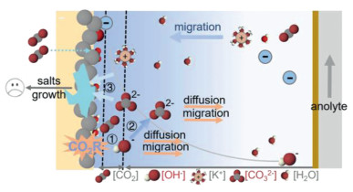
 DownLoad:
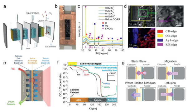
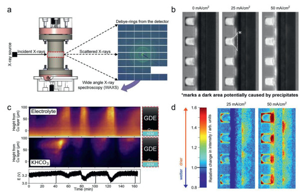
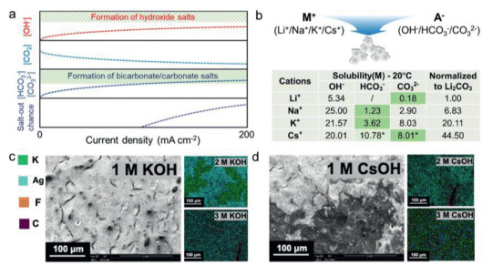
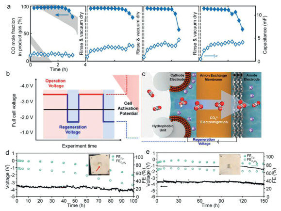
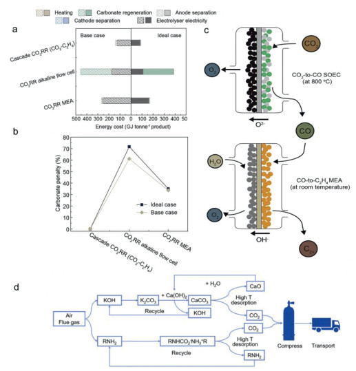

 下载:
下载:


 下载:
下载:
