Citation:
Guoliang Liu, Haitao Deng, Jianning Yu, Zhongpeng Zhu, Lei Jiang, Ye Tian. Bioinspired three-dimensional superspreading on helical leaves-stem arrays: Mechanisms and applications in evaporators[J]. Chinese Chemical Letters,
2026, 37(11): 111854.
doi:
10.1016/j.cclet.2025.111854
Bioinspired three-dimensional superspreading on helical leaves-stem arrays: Mechanisms and applications in evaporators
English
Bioinspired three-dimensional superspreading on helical leaves-stem arrays: Mechanisms and applications in evaporators
Received Date:
17 July 2025 Accepted Date:
17 September 2025 Revised Date:
10 September 2025 Available Online:
15 November 2026
Abstract:
Bioinspired surfaces exhibiting superspreading properties have garnered notable attention for their potential in various applications, including heat management and water purification. However, achieving three-dimensional (3D) superspreading remains a challenge. Here, a helical leaves-stem array (HLSA) mimicking the moss Racomitrium canescens is fabricated, which enables 3D superspreading, a process that facilitates rapid multidirectional spreading, enhances water retention, and ensures efficient liquid distribution across the surface, ultimately supporting sustained evaporation. The wedge-shaped interfaces between the leaves and stem, along with the continuous 3D microchannels formed by the helical arrangement of the leaves, drive this phenomenon through enhanced capillary forces. Inspired by this 3D superspreading mechanism, HLSA-based evaporators demonstrate promising applications in both thermal management and solar desalination, achieving a temperature reduction of 8.3 °C in cooling systems and a seawater evaporation rate of 1.08 kg m⁻2 h⁻1. Notably, the seawater evaporation process features an autonomous salt crystal removal and exhibits multi-angle light absorption. These findings offer insights into bioinspired thermal dissipation and pave the way for advanced evaporative systems.
Dynamic superspreading surfaces, on which liquids rapidly spread and evaporate, have attracted growing attention due to their diverse applications in fields such as film preparation [1,2], liquid separation [3-6], heat management [7,8] and self-cleaning [9]. Mosses, renowned for their superhydrophilicity and water-absorbing properties [10-12], provide a natural model for such dynamic spreading processes. Mosses, through transpiration, not only modulate ambient temperature and humidity [13-15], but also offer potential solutions for sustainable technologies, including green roof system [16,17], water purification [18], underwater oil-repellency [19]. Despite these promising applications, elucidating the underlying mechanism of liquid dynamic spreading on moss surfaces, particularly in three-dimensional (3D) configurations, remain poorly understood.
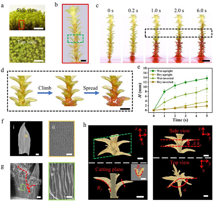
Herein, we present a unique water superspreading phenomenon observed on the surfaces of moss Racomitrium canescens (R. canescens, Fig. 1a), wherein water ascends against gravity and infiltrates the entire leaf surfaces, exhibiting a 3D superspreading behavior. This behavior not only enhances water distribution to achieve uniform allocation but also improves water retention capacity across the entire surface. Inspired by this natural phenomenon, we utilized 3D printing technology to engineer a bioinspired helical leaves-stem array (HLSA), featuring helically arranged, curved leaves around a central stem, which create wedge-shaped interfaces and continuous 3D microchannels. We show that water ascends along the HLSA surfaces via a 3D water channel delineated by the stem-leaf interspace, ultimately reaching a height of 72 mm within 60 s. Simultaneously, water infiltrates the leaves surfaces, thereby achieving a 3D superspreading process. We identify the capillary rise mechanism in corner-slit geometries as a key contributor to this behavior, while the oriented grooves on the leaf and stem surfaces increase roughness and enhance surface superhydrophilicity. Leveraging the unique dynamics of liquid behavior, we design and fabricate two advanced evaporators: One for cooling and one for solar desalination based on the HLSA system. The cooling evaporator demonstrated a temperature reduction of 8.3 ℃, while the solar evaporator achieves a solar-driven seawater evaporation rate of 1.08 kg m−2 h−1, featuring an autonomous salt crystal removal function and exhibiting multi-angle light absorption capability. The present study would open new possibilities for the design of self-cleaning, efficient evaporators with enhanced water retention and transport properties, paving the way for more sustainable solutions in thermal management and desalination.
Figure 1
Figure 1.
Structural features and 3D water climb properties of the superhydrophilic surfaces of R. canescens. (a) Optical images of clumped R. canescens. Scale bar: 10 mm. (b) Optical image of a branch of R. canescens. Scale bar: 1 mm. (c) In situ optical observation of the 3D capillary rise process on R. canescens. The bulk water was dyed with 0.01 wt% Rhodamine B. Scale bar: 3 mm. (d) Details of water climbing process on R. canescens surface (black dotted line in Fig. 1c). Scale bar: 1 mm. (e) Water climbing process on wet or dry R. canescens surfaces. (f) SEM images of leaf of R. canescens, showing oblong-lanceolate leaf shape and orientated papillae array on leaf surfaces. Scale bar: (i) 200 μm; (ii) 20 μm. (g) ESEM images of stem of R. canescens, showing the wedge corners (red dotted lines) and wrinkled stem surfaces. Scale bar: (i) 50 μm; (ii) 20 μm. (h) Reconstructed 3D nano-CT images of the upper part of R. canescens (light green rectangle in Fig. 1b), exhibiting longitudinal curvature of radius R1, transverse curvature of radius R2, the height difference Δhα and the rotation angle α. Scale bar: 500 μm. The error bars represent the standard deviations (n = 3).
The water transport capability is investigated by inserting a piece of R. canescens branch (Fig. 1b) vertically into a water bath (Fig. 1c). The water is dyed with Rhodamine B. In situ optical microscope images of the water transport process show that water can climb vertically along the stem at an average velocity of 2.8 mm/s in the initial 5.0 s and then infiltrates the leaves. As shown in Fig. 1d, the water climbing process involves water moving into the stem-leaf interspace, rising upward driven by the capillary force and infiltrating the leave surfaces. That is, a 3D capillary water-climbing channel is formed by the unique stem-leaf structure.
Whether plants of R. canescens are placed upright or inverted, or whether their surfaces are wet (when leaves are open) or dry (when leaves are closed), water can climb along the stem against gravity and eventually infiltrate the whole plant surface, which is essential for its survival. Among these, water climbs the fastest from the root to the tip on the wet moss surfaces (Fig. 1e). On occasion of water droplets given to the upper part of the test specimens, water spreads the fastest follow the path of the wet moss surfaces from the root to the tip (Fig. S1 in Supporting information). FTIR-ATR characterizes the main surface composition of dried leaves is cellulose (Fig. S2 in Supporting information). Hydrophilic surfaces combined with its unique three-dimensional constructure enable water to climb along R. canescens against gravity and spread in a 3D configuration.
Optical images show that the leaves of R. canescens (Figs. 1b and d) grow helically around the stem, with the upper part curves outward, while the lower part grows close to the stem. Scanning electron microscopy (SEM) images show that the shape of R. canescens leaf is oblong-lanceolate (2000 μm in length and 800 μm in width), with an oriented papillae array (Fig. 1f). Environmental scanning electron microscope (ESEM) images demonstrate that the lower part of each leaf is close to the wrinkled stem, thereby forming narrow wedge corners, as shown in Fig. 1g (the leaf is gently curved downward beforehand for better observation). Both sides of the leaf base extend downward to form the special “leaf tails”, which are about 100-300 μm in length (Fig. 1g, red dotted line). In addition, on the surface of the cylindrical stem (150 μm of radius, r), oriented wrinkles (10 μm in width) grow, enhancing surface superhydrophilicity. To demonstrate the arrangement of leaves along the stem in a 3D view, we utilized nano-Computed Tomography (nano-CT) to reconstruct the structure details of R. canescens (Fig. 1h). The upper part of R. canescens branch (light green rectangle shown in Fig. 1b) was selected for observation. As the reconstructed 3D nano-CT images show, each leaf exhibits a dual-reentrant topography with a longitudinal curvature of radius R1 and a transverse curvature of radius R2. The leaves overlap each other, arranging in a helical pattern. Interestingly, due to the density of leaves, a leaf located on the lower side can respectively cover one side of the leaf base of the upper two leaves. The height difference between the two adjacent leaves is Δhα (Δhα is around 130-530 μm), and the rotation angle between two adjacent leaves is α (α is around 75°-142°).
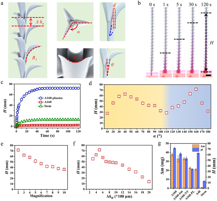
Inspired by our observations, we employed 3D printing technology to fabricate the HLSA (Fig. 2a and Fig. S3 in Supporting information). Acrylic photosensitive resin was used in 3D printing process. The HLSA consists of numerous leaves arranged helically around one central stem, with adjacent-leaves height Δhα and rotation angle α. Oriented grooves are arranged on the surfaces of both the stem and the leaves. The longitudinal curvature for each leaf is R1 and the transverse curvature is R2. In addition, the basal regions of each leaf extend downward along both lateral edges, forming unique wedge corners (blue curve in Fig. 2a). The horizontal distance between the leaf and the stem is d and the outward bending angle of the leaf is θ.
Figure 2
Figure 2.
Design, fabrication, and 3D capillary rise properties of bioinspired HLSA. (a) Optical images of bioinspired HLSA, showing numerous curving leaves arranged helically around the central stem, with the height difference Δhα, the rotation angle α, the longitudinal curvature R1, the transverse curvature R2, the transverse distance between leaves and stems d, and the longitudinal angle θ. Orientated grooves arranged on the leaves and stem surfaces. (b) In situ optical observation of the 3D capillary rise process on the HLSA. The bulk water was dyed with 0.01 wt% Rhodamine B. Scale bar: 5 mm. (c) Capillary rise height (H) of water versus time on HLSA. The label A160-plasma refers to HLSAs with α = 160° and oxygen plasma treatment; A160 refers to HLSAs designed with α = 160° but without oxygen plasma treatment. Stem refers to the leafless samples. (d) H versus α on HLSA. (e) H versus HLSA with different 3D print multiples. (f) H versus Δhα on HLSA. (g) Leaf arrangement and structure influence H and liquid carrying capacity (Δm). A160 refers to the HLSA with α = 160°. A160-Sm refers to the HLSA with α = 160° and smooth surfaces (without the designed aligned grooves). A160-NT refers to the HLSA with α = 160°, but the tails of the leaves are cut. A160-PL refers to the HLSA with α = 160°, but the leaves are flat. A40 refers to the HLSA with α = 40°. Stem refers to the grooved cylinder without leaves around it. The error bars represent the standard deviations (n = 3).
In situ optical images show the capillary rise and 3D superspreading process on the surfaces of the HLSA inserted into dyed water bath (Fig. 2b). The parameters of the model are designed with α = 160°, Δhα = 500 μm, d = 80 μm and θ = 10°. Oxygen plasma treatment was used to enhance the hydrophilicity of the surfaces (Fig. S4-S7 in Supporting information). The time-dependent variation of water climbing height (H) is plotted in Fig. 2c. Dyed water would climb upward on the HLSA, infiltrating the leaf surfaces, and finally reached the highest point at 72 mm within 60 s, while 13 mm on grooved stem without leaves, suggesting the importance of leaves on the anti-gravity water climb process. Beyond structural factors, surface hydrophilicity also exerts a significant influence on water climbing process on HLSA. HLSA structures without oxygen plasma treatment exhibited no water ascent (red curve with square symbols in Fig. 2c). For HLSAs fabricated from different resins, divergent chemical properties led to varying degrees of hydrophilicity after oxygen plasma treatment, resulting in differential water climbing heights (Fig. S8 in Supporting information). Higher surface hydrophilicity correlated strongly with increased water climbing height. In summary, a 3D superhydrophilic microchannel has been successfully integrated on the surfaces of HLSA, enabling water to ascend and spreading into a 3D pattern.
On occasion of α > 120°, we observed a transition in the leaf arrangement from a single-helix configuration to a double-helix configuration (Fig. S9 in Supporting information). This phenomenon can be readily explained through geometric principles. The rotation angle between the first leaf and the third leaf is defined as β, then we get the equation:
β=2π−2α
(1)
Once α > 120°, then β < α, which results in the first and third leaves being positioned closer. Consequently, the original single helical leaf array is divided into two helical leaf arrays, each characterized by β (overlooking counterclockwise) and height difference Δhβ (Δhβ = 2Δhα). The H-α scatter plot diagram indicates distinct water climbing configurations on the HLSA as α increases (Fig. 2d). For α < 120°, the leaves arrange in a single helix configuration, with the H value peaking at α = 40°. When α > 120°, the structure transitions from a single helix to a double helix configuration, leading to an increase in climbing height, which reaches its maximum at α = 160°.
The H on HLSA replicas of varying sizes is illustrated in Fig. 2e. Limited by the mechanical strength of the resin, we were unable to fabricate replica with a magnification ratio of 1:1 of moss R. canescens. As the magnification increases from 2X to 10X, there was a corresponding decrease in the climbing height. As the dimensions of the replicas enlarged, the stem-leaf interspace correspondingly increases, leading to a reduction in capillary force. Furthermore, with the augmentation of magnification, the effect of gravity on the water climbing process becomes pronounced and must be taken into consideration. The spatial relationships between individual leaves and central stem, such as Δhα (Fig. 2f), d (Fig. S10a in Supporting information) and θ (Fig. S10b in Supporting information), affect the morphology of the 3D capillary water-climbing channel. These factors, in turn, exert a detrimental effect on the capillary force.
On traditional 2D superhydrophilic surfaces, superspreading time (ST, the time required for a water droplet to be completely spread out until the contact angle approaches 0°) is used to describe the dynamic spreading phenomenon of liquids [20]. Herein, in order to describe 3D superspreading process, we measured H within 120 s and liquid carrying capacity (Δm) on series of designed HLSA models. The Δhα is fixed to be 500 μm and the magnification is 2X so that H would be positively correlated with the 3D spreading area. As is shown in Fig. 2g, A160 refers to the HLSA with α = 160°. A160-Sm refers to the HLSA with α = 160° and smooth surfaces (without the designed aligned grooves). A160-NT refers to the HLSA with α = 160°, but the tails of the leaves are cut. A160-PL refers to the HLSA with α = 160°, but the leaves are flat. A40 refers to the HLSA with α = 40°. Stem refers to the grooved cylinder without leaves around it. The wedge corners in leaf tails and the stem-leaf interspace provide a 3D channel for water to rise up faster and higher, while the aligned micro-grooves enhance the superspreading capability (Fig. S11 in Supporting information). Comparing Stem group with others, it is obvious that the stem-leaf interspace is vital for water retention. Comparing the double helix configuration of A160 with the single helix configuration of A40, it is evident that the arrangement of leaves in the former provides a more expansive reservoir for water retention, notwithstanding the identical density of the leaves.
Similarly to the superhydrophilic properties of moss R. canescens, the HLSA promotes the upward movement of water against gravity irrespective of its orientation, whether upright or inverted (Fig. S12 in Supporting information). When water is introduced to the central region of the HLSA, a 3D superspreading and water retention mechanism is activated, operating in both upward and downward directions (Fig. S13 in Supporting information). In this work, we focused on the 3D capillary rise dynamics of water in its upright configuration.
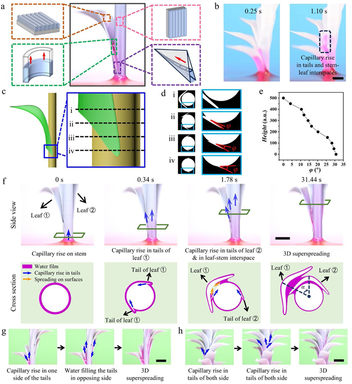
To elucidate the function of the leaf on the 3D capillary superspreading process, a simplified single-leaf HLSA was fabricated, featuring only one piece of leaf on the stem (Fig. 3a). The HLSA model can be divided into two distinct components: the 2D superspreading model and the 3D water climbing model. The former is predicated on the superhydrophilic oriented grooves, whereas the latter can be dissected into the capillary rise dynamics between curved parallel plates and along the wedge corners. In situ optical observation demonstrates that the wedge corners of the leaf tails direct water into the stem-leaf interspace, facilitating its upward movement and infiltrating across the leave surfaces (Fig. S14 in Supporting information). To confirm the water climbing path on the surfaces of HLSA, we fabricated the HLSA using a highly transparent resin (Fig. 3b). Consistent with our hypothesis, water was observed to ascend along the 3D water channel established by the leaf tails and the stem-leaf interfaces.
Figure 3
Figure 3.
Mechanism of 3D superspreading process on HLSA. (a) Simplified HLSA model, including the superhydrophilic oriented grooves, the curved parallel plates and the wedge corners. (b) 3D water channel established by the leaf tails and the stem-leaf interfaces. The HLSA model was fabricated by highly transparent resin. Scale bar: 3 mm. (c) The enlarged view of the leaf base on the single-leaf HLSA model. (d) Cross sections of wedge corners in different height. The diagrams (i) to (iv) correspond to the black dotted lines (i) to (iv) in Fig. 3c. The opening angle of the wedge corner is φ. (e) Line chart shows that φ declines from roughly 32° to 0° with the height increase. (f) In-situ optical images of water climbing process on the two-leaf model. The rotation angle α for the model is 50°. Scale bar: 5 mm. (g) In situ photographs of the water climbing process on the single-helical model with α = 40°. Scale bar: 3 mm. (h) In situ photographs of the water climbing process on the double-helical model with α = 160°. Scale bar: 3 mm.
To reveal the dynamics of the climbing process, we conducted an in-depth analysis of the structural characteristics of the wedge corner between the leaf tails and the stem (Figs. 3c and d). The cross-sectional diagrams depicted in Fig. 3e establish a gradual reduction in the opening angle, φ, as the height increases. This reduction begins from an initial angle of approximately 32° at the base and diminishes to 0° at the apex. Consequently, the wedge corner transitions into a parallel plate configuration, which can be perceived as an angle of 0°.
The capillary rise height in the wedge corner, He(x), is given by the following equation [21-23]:
He(x)=(2γcosδ)/ρφgx
(2)
where γ, δ, ρ, φ, and g are the surface tension, the water contact angle, the density of the liquid, the corner opening angle and the gravitational constant, respectively.
Furthermore, as multiple leaves emerged, the climbing process became more complex. Fig. 3f exhibits in-situ optical images capturing the water climbing process on a HLSA model designed with a pair of leaves, with α = 50°. Initially, water ascends along the corners of leaf tails before entering the stem-leaf interspace. Concurrently, water spreads laterally and infiltrates the leaves. As the tail of the second leaf inserts into the stem-leaf interspace of the first, water continues its ascent along the corner of the second leaf's tail, and enters the upper stem-leaf interspace immediately. Expanding upon the fundamental climbing model depicted in Fig. 3f to incorporate helical configurations, we obtain the single helical model and double helical model (Figs. 3g and h). The blue arrows indicate the direction of water flow. On the surfaces of single helical model (α = 40°), water ascends along the unilateral tails arranged in a helical pattern, penetrates the stem-leaf interspace, and fills the opposing side of the tails in a sequential manner. In contrast, on double helical model (α = 160°), water climbs up from the stem-leaf interspace of the lower two leaves, and enters the leaf tails of the upper two leaves. In conclusion, it can be stated that this double helical configuration efficiently exploits capillary structure on both sides of the leaf tails.
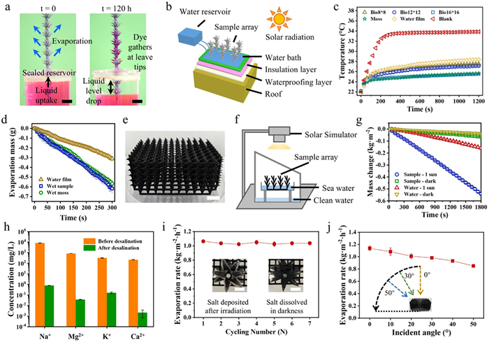
The quick 3D superspreading process on the surfaces of HLSA can be harnessed for efficient liquid evaporation applications. A represented demonstration is shown in Fig. 4a, where the HLSA evaporator is submerged into a reservoir containing red-dyed water. The reservoir is sealed around the HLSA. Over time, the liquid level in the reservoir drops as water rises along the stem of the HLSA and evaporates from the surfaces of the structure. The non-volatile dye concentrates and precipitates at the leaf tips, providing a visual indication of the regions of the highest evaporative flux. This experiment demonstrated the potential of the HLSA for continuous liquid transportation and evaporation.
Figure 4
Figure 4.
HLSA-based evaporators. (a) One HLSA sample is submerged in a sealed reservoir of red-dyed water. Continuous water transport and evaporation occurs until the reservoir is depleted. Scale bar: 10 mm. (b) Simulation experiment diagram of bioinspired HLSA-based cooling evaporator reducing indoor temperature through evaporative heat dissipation. (c) Internal temperature variation with different HLSA-based cooling evaporators. Bio refers to the bioinspired HLSA array. 8 × 8, 12 × 12, 16 × 16 refers to the arrangement of a single sample in the array. (d) Time-dependent water mass changes of HLSA-based cooling evaporator. (e) Photograph of HLSA-based evaporator for Solar-driven seawater evaporation. Scale bar: 10 mm. (f) Schematic diagram of the solar seawater desalination device in the laboratory. (g) Time-dependent seawater mass changes of HLSA-based evaporator. (h) Ionic concentration for the real seawater before and after solar thermal desalination. (i) Cyclic evaporation performance of HLSA-based evaporator in actual seawater. Interior photographs show the spontaneous dissolution of salt crystals in darkness. Scale bar: 5 mm. (j) Evaporation rate of HLSA-based evaporator at various incidence angles (0°, 10°, 20°, 30°, 40° and 50°). The error bars represent the standard deviations (n = 3).
Leveraging the superior evaporative heat dissipation capacity of HLSA, a cooling evaporator, consisting of the designed HLSA array, water bath, and an injection pump for water supply, was designed and fabricated (Fig. 4b and Fig. S15 in Supporting information). To evaluate the thermal effects, a solar radiation device was set up to measure the temperature change inside the model house. Model houses made from box-shaped polystyrene foam were prepared, with the roof plate pasted with matte black paper to reduce radiation reflectivity. The HLSA-based cooling evaporator was installed on top of the roof plate. Solar irradiation was fixed at 100 mW/cm2 (one sun illumination). A piece of naturally grown R. canescens moss mat, thoroughly sprayed with water, was prepared as comparison. As shown in Fig. 4c, the 16 × 16 arrayed HLSA-based cooling evaporator (blue-block scatter) performed similarly to the naturally grown R. canescens moss mat (green-star scatter). After continuous solar irradiation for 30 min, the HLSA-based cooling evaporator maintained a lower inner temperature compared to the blank roof, with a temperature difference of 8.3 ℃ (Fig. 4c) and an evaporation rate of 0.117 g/min (Fig. 4d), demonstrating the potential application of HLSA for evaporative heat dissipation.
While existing biomimetic strategies primarily focus on optical absorption enhancement, the persistent challenges in mass transport limitations necessitate innovative structural engineering for sustainable solar evaporation systems [24]. Owing to the excellent chemical and thermal stability of the HLSA structure (Fig. S16), we designed the HLSA-based solar evaporators using a black composite resin and selected carbon black powder as the photothermal material (Fig. 4e). A purification apparatus composed of solar simulator, HLSA-based evaporator and brine container is set up to simulate the practical water purification process (Fig. 4f). Natural seawater samples from the Bohai Sea are used as the desalination sample. During evaporation period, the HLSA-based evaporator achieved a steam generation rate of 1.08 kg m−2 h−1 under one sun illumination (Fig. 4g). As shown in Fig. 4h, after desalination, the ion concentration, measured by inductively coupled plasma mass spectroscopy (ICP-MS), exhibited a substantial decrease of at least four orders of magnitude, thus fully meeting the WHO drinking water requirements. Fig. 4i illustrates that the HLSA-based solar evaporator maintained a stable evaporation rate with seawater over a 7-day period, under one sun illumination for 9 h every day. Notably, the solar evaporator exhibits an autonomous salt crystal removal function, as depicted in the inset illustrations of Fig. 4i. Upon exposure to light for 9 h, salt crystals are observed to precipitate from the surfaces. These precipitated salts are found to redissolve into the water when the environment transitions to darkness, thereby demonstrating its self-cleaning properties against salt pollution. Fig. 4j presents that the HLSA-based evaporator retains a robust steam generation ability across a range of incidence angles ranging from 0° to 50°, with 25% efficiency loss at 50° illumination, indicating multi-angle light-absorption capability.
In summary, inspired by R. canescens, our biomimetic HLSA achieves high-efficiency 3D liquid propagation. We reveal that the 3D superspreading mechanism originates from continuous helical water channels and enhanced capillary force at wedge corners. The oriented grooves on leaves and stems further enhance liquid infiltration. Furthermore, we have extended the application of the HLSA for evaporative heat dissipation, demonstrating its potential in artificial cooling surfaces and solar-driven seawater desalination.
An important future direction is the translation of lab-scale HLSA fabrication into cost-effective mass production, which demands further optimization of materials and processes. Advancing this area could inspire new strategies for thermal regulation and water treatment technologies, paving the way for innovative biomimetic engineering solutions in both environmental and industrial applications.
CRediT authorship contribution statement
Guoliang Liu: Writing – original draft, Validation, Methodology, Investigation, Formal analysis, Data curation. Haitao Deng: Methodology, Data curation. Jianning Yu: Methodology, Data curation. Zhongpeng Zhu: Methodology, Investigation. Lei Jiang: Resources, Conceptualization. Ye Tian: Writing – review & editing, Supervision, Funding acquisition, Formal analysis, Conceptualization.
Declaration of competing interest
The authors declare that they have no known competing financial interests or personal relationships that could have appeared to influence the work reported in this paper.
Acknowledgments
This work was supported by the National Natural Science Foundation of China (No. 22090052), Frontier Science Key Projects of CAS (No. ZDBS-LY-SLH022), Key R&D Project of Shandong Province (No. 2022CXGC010302), and Xiaomi Young Talents Program.
Supplementary materials
Supplementary material associated with this article can be found, in the online version, at doi:10.1016/j.cclet.2025.111854.
[1]
Z. Zhu, Y. Tian, Y. Chen, et al., Angew. Chem. Int. Ed. 56 (2017) 5720–5724. doi: 10.1002/anie.201700039
Figure 1
Structural features and 3D water climb properties of the superhydrophilic surfaces of R. canescens. (a) Optical images of clumped R. canescens. Scale bar: 10 mm. (b) Optical image of a branch of R. canescens. Scale bar: 1 mm. (c) In situ optical observation of the 3D capillary rise process on R. canescens. The bulk water was dyed with 0.01 wt% Rhodamine B. Scale bar: 3 mm. (d) Details of water climbing process on R. canescens surface (black dotted line in Fig. 1c). Scale bar: 1 mm. (e) Water climbing process on wet or dry R. canescens surfaces. (f) SEM images of leaf of R. canescens, showing oblong-lanceolate leaf shape and orientated papillae array on leaf surfaces. Scale bar: (i) 200 μm; (ii) 20 μm. (g) ESEM images of stem of R. canescens, showing the wedge corners (red dotted lines) and wrinkled stem surfaces. Scale bar: (i) 50 μm; (ii) 20 μm. (h) Reconstructed 3D nano-CT images of the upper part of R. canescens (light green rectangle in Fig. 1b), exhibiting longitudinal curvature of radius R1, transverse curvature of radius R2, the height difference Δhα and the rotation angle α. Scale bar: 500 μm. The error bars represent the standard deviations (n = 3).
Figure 2
Design, fabrication, and 3D capillary rise properties of bioinspired HLSA. (a) Optical images of bioinspired HLSA, showing numerous curving leaves arranged helically around the central stem, with the height difference Δhα, the rotation angle α, the longitudinal curvature R1, the transverse curvature R2, the transverse distance between leaves and stems d, and the longitudinal angle θ. Orientated grooves arranged on the leaves and stem surfaces. (b) In situ optical observation of the 3D capillary rise process on the HLSA. The bulk water was dyed with 0.01 wt% Rhodamine B. Scale bar: 5 mm. (c) Capillary rise height (H) of water versus time on HLSA. The label A160-plasma refers to HLSAs with α = 160° and oxygen plasma treatment; A160 refers to HLSAs designed with α = 160° but without oxygen plasma treatment. Stem refers to the leafless samples. (d) H versus α on HLSA. (e) H versus HLSA with different 3D print multiples. (f) H versus Δhα on HLSA. (g) Leaf arrangement and structure influence H and liquid carrying capacity (Δm). A160 refers to the HLSA with α = 160°. A160-Sm refers to the HLSA with α = 160° and smooth surfaces (without the designed aligned grooves). A160-NT refers to the HLSA with α = 160°, but the tails of the leaves are cut. A160-PL refers to the HLSA with α = 160°, but the leaves are flat. A40 refers to the HLSA with α = 40°. Stem refers to the grooved cylinder without leaves around it. The error bars represent the standard deviations (n = 3).
Figure 3
Mechanism of 3D superspreading process on HLSA. (a) Simplified HLSA model, including the superhydrophilic oriented grooves, the curved parallel plates and the wedge corners. (b) 3D water channel established by the leaf tails and the stem-leaf interfaces. The HLSA model was fabricated by highly transparent resin. Scale bar: 3 mm. (c) The enlarged view of the leaf base on the single-leaf HLSA model. (d) Cross sections of wedge corners in different height. The diagrams (i) to (iv) correspond to the black dotted lines (i) to (iv) in Fig. 3c. The opening angle of the wedge corner is φ. (e) Line chart shows that φ declines from roughly 32° to 0° with the height increase. (f) In-situ optical images of water climbing process on the two-leaf model. The rotation angle α for the model is 50°. Scale bar: 5 mm. (g) In situ photographs of the water climbing process on the single-helical model with α = 40°. Scale bar: 3 mm. (h) In situ photographs of the water climbing process on the double-helical model with α = 160°. Scale bar: 3 mm.
Figure 4
HLSA-based evaporators. (a) One HLSA sample is submerged in a sealed reservoir of red-dyed water. Continuous water transport and evaporation occurs until the reservoir is depleted. Scale bar: 10 mm. (b) Simulation experiment diagram of bioinspired HLSA-based cooling evaporator reducing indoor temperature through evaporative heat dissipation. (c) Internal temperature variation with different HLSA-based cooling evaporators. Bio refers to the bioinspired HLSA array. 8 × 8, 12 × 12, 16 × 16 refers to the arrangement of a single sample in the array. (d) Time-dependent water mass changes of HLSA-based cooling evaporator. (e) Photograph of HLSA-based evaporator for Solar-driven seawater evaporation. Scale bar: 10 mm. (f) Schematic diagram of the solar seawater desalination device in the laboratory. (g) Time-dependent seawater mass changes of HLSA-based evaporator. (h) Ionic concentration for the real seawater before and after solar thermal desalination. (i) Cyclic evaporation performance of HLSA-based evaporator in actual seawater. Interior photographs show the spontaneous dissolution of salt crystals in darkness. Scale bar: 5 mm. (j) Evaporation rate of HLSA-based evaporator at various incidence angles (0°, 10°, 20°, 30°, 40° and 50°). The error bars represent the standard deviations (n = 3).


 DownLoad:

 下载:


 下载:

