Ag3PO4/g-C3N4 S-scheme heterojunction photoanode coupled with natural air diffusion electrode for efficient organic pollutants degradation and H2O2 generation
Citation:
Jiangli Sun, Chaohui Zhang, Yican Zhang, Chunhong Fu, Ruiheng Liang, Zhongzheng Hu, Ge Song, Minghua Zhou. Ag3PO4/g-C3N4 S-scheme heterojunction photoanode coupled with natural air diffusion electrode for efficient organic pollutants degradation and H2O2 generation[J]. Chinese Chemical Letters,
2026, 37(5): 111839.
doi:
10.1016/j.cclet.2025.111839
Ag3PO4/g-C3N4 S-scheme heterojunction photoanode coupled with natural air diffusion electrode for efficient organic pollutants degradation and H2O2 generation
English
Ag3PO4/g-C3N4 S-scheme heterojunction photoanode coupled with natural air diffusion electrode for efficient organic pollutants degradation and H2O2 generation
Key Laboratory of Pollution Process and Environmental Criteria, Ministry of Education, College of Environmental Science and Engineering, Nankai University, Tianjin 300350, China
b.
Tianjin Key Laboratory of Environmental Technology for Complex Trans-Media Pollution, College of Environmental Science and Engineering, Nankai University, Tianjin 300350, China
c.
Tianjin Advanced Water Treatment Technology International Joint Research Center, College of Environmental Science and Engineering, Nankai University, Tianjin 300350, China
Received Date:
03 April 2025 Accepted Date:
15 September 2025 Revised Date:
07 September 2025 Available Online:
15 May 2026
Abstract:
The utilization of photoelectrocatalytic (PEC) technology for water pollution treatment and value-added chemical production is important in sustainable development strategies. A system combining Ag3PO4/g-C3N4 S-scheme heterojunction photoanodic oxidation with natural air diffusion electrode (NADE) reduction was designed. The PEC system could remove 94.5% of tetracycline (TC) with the first-order kinetic rate constant of 0.148 min-1, while the H2O2 yield in the cathodic chamber reached 4.3 µmol-1 h-1 cm-2 under 2.0 V cell voltage. The rate constant of TC degradation by the Ag3PO4/g-C3N4 coupled NADE PEC system was 4.4 times that of Ag3PO4/g-C3N4 coupled Pt PEC system (0.034 min-1). This was attributed to the synergistic effect between accelerated photoanode carrier transfer and increased H2O2 yield. The production of H2O2 in the cathode chamber of the PEC system with the presence of TC was 2.3 times that of absence of TC (1.9 µmol-1 h-1 cm-2). The active substances playing a major role in this PEC system were mainly h+ followed by •OH. Significantly, the efficient operation of the PEC system under actual sunlight will be conducive to the exploration of practical applications in the future. This study provides new insights for constructing efficient cathode-anode coupled PEC systems for water purification and simultaneous H2O2 production.
With the development of society, the problems of environmental pollution and resource scarcity have become increasingly prominent [1]. A healthy water environment is vital to social development. Unfortunately, the high toxicity of antibiotics and their intermediates becomes a high ecological risk and a threat to human health [2]. Studies have indicated that tetracycline concentrations in wastewater from aquaculture operations can reach 20 mg/L [3]. Compared to conventional wastewater treatment conditions, solar energy has received attention as an environmentally friendly and inexhaustible energy source capable of driving catalytic reactions in an energy-efficient manner [4]. Therefore, it is important to develop a bifunctional strategy for antibiotic removal and resource production.
In particular, photoelectrocatalytic (PEC) technology utilizing visible light is expected to be an effective solution to environmental problems and energy crises. The PEC system is a balanced reaction system consisting of a half-cell for oxidation reactions and a half-cell for reduction reactions to ensure electroneutrality [5]. The reaction of the PEC system is easy to manipulate and the electrodes operate under mild conditions such as light and external power supply [6]. In order to maximize the use of power input, we tend to utilize both anode and cathode for redox reactions in PEC processes [7]. For example, wastewater treatment is combined with the production of H2 [8], H2O2 [9], and CO2-derived chemicals [10]. However, most of the current research on PEC systems focuses on one or the other, and little attention has been paid to the electrode reactions and products at the counterpart electrode.
In recent years, a number of semiconductor materials have been extensively investigated for PEC applications. Ag3PO4 has rapidly attracted attention in the photocatalytic field due to its band gap (2.45 eV), high quantum efficiency and visible light absorbance [11]. However, the following aspects of Ag3PO4 limit its rapid development, including low reduction potential, susceptibility to photo-corrosion, and rapid carrier recombination in single-component semiconductors [12]. To overcome the above problems, combining different semiconductor photocatalysts to construct heterojunctions is one of the most promising schemes. S-scheme heterojunctions integrate oxidized and reduced semiconductors with efficient photogenerated carrier separation, strong interfacial driving force and redox capacity [13]. It was shown that various combinations of organic and inorganic semiconductor photocatalysts were used to construct S-scheme heterojunction photoanodes, such as metal sulfides [14], metal-organic frameworks [15], carbon nitride [16], and metal oxides [17]. For example, Dang et al. prepared N-doped carbon dots (NCD) incorporated g-C3N4/α-Fe2O3 S-scheme photoanodes to achieve efficient trimethoprim (95%) degradation and hydrogen evolution (550 µmol cm-2 h-1) [18]. The enhanced PEC activity of the system can be attributed to the excellent electron transfer and light absorption properties of the S-scheme heterojunction photoanode. Chen et al. designed In2S3/MnIn2S4 S-scheme bifunctional electrodes for photocathode O2 reduction reaction (ORR, 2108 µmol/L) and photoanode Cl- oxidation reaction (ClOR, 28.5 mg/L) [19]. The results showed that the In2S3/MnIn2S4 photoelectrode possessed better photogenerated carrier transport ability as well as excellent activity toward ORR and ClOR. In addition, many studies have shown that the catalytic efficiency and corrosion resistance of Ag3PO4 can be improved by combining with graphitic carbon nitride (g-C3N4) to improve the photogenerated electron-hole pair separation [20]. More importantly, g-C3N4 is a low-cost metal-free semiconductor catalyst. The relatively negative conduction band (CB) edge position (band gap of about 2.7 eV) gives it excellent reducing properties [21]. Besides, the unique s-triazine ring structure and high condensation of g-C3N4 nanosheets provide excellent chemical stability [22]. For the study of Ag3PO4/g-C3N4 composites, photocatalytic experiments are mainly carried out in the form of powder catalysts, however, this is not conducive to the recycling of materials. Therefore, Ag3PO4 and g-C3N4 were selected to construct S-scheme heterojunction photoanodes for efficient PEC degradation of antibiotics.
In order to fully utilize the redox effect of the PEC system, the oxygen reduction reaction (ORR), which has thermodynamic advantages over the hydrogen evolution reaction (HER), was utilized as the cathode reaction [23]. The photogenerated electron was realized to reduce oxygen value-added H2O2 at the cathode while the coupling mechanism between photoanode and cathode was explored. It is well known that hydrogen peroxide (H2O2) is widely used as an environmentally friendly oxidant in chemical manufacturing and environmental remediation [24]. However, most of the commercially available H2O2 is synthesized by anthraquinone oxidation, which is a complex process that generates secondary pollution and high energy consumption [25]. Therefore, a low energy consumption and mild reaction conditions are needed to produce H2O2.The cathode was chosen to be natural air diffusion electrode (NADE) that does not require air explosion, which allows air to diffuse naturally into the ORR interface and has a high performance in producing H2O2 [26]. There have been studies coupling photoanodic oxidation for water purification with cathodic H2O2 production. For example, Liang et al. [23] coupled an oxygen vacancy-rich black TiO2 photoanode with NADE for simultaneous sulfamethazine removal (98.3%, 1 h) and H2O2 production (6.83 µmol h-1 cm-2). In addition, Xiao et al. [27] constructed a two-chamber cell while WO3 photoanode degraded bisphenol A and dopamine modified carbon felt to produce H2O2. Under the optimal conditions, 92% of BPA was degraded within 2 h and 5.4 mmol/L of H2O2 was obtained. At present, the system of Ag3PO4/g-C3N4 S-scheme heterojunction photoanodic oxidation combined with NADE reduction has not been reported.
Eventually, the system of Ag3PO4/g-C3N4 photoanodic degradation of TC synchronized with NADE cathodic production of H2O2 was constructed in this paper. Based on photoelectrochemical characterization, in-situ irradiation X-ray photoelectron spectroscopy (XPS) and density functional theory (DFT) calculation analysis, the resulting Ag3PO4/g-C3N4 photoanode had a staggered energy band structure and an S-scheme heterojunction carrier migration path. The applied voltage promoted carrier separation and transfer at the photoanode, and the high synergistic effect of the electrocatalytic (EC) and photocatalytic (PC) processes enhanced the current density of the PEC system. The Ag3PO4/g-C3N4-NADE system also enabled efficient degradation of organic pollutants and H2O2 production under actual sunlight. Finally, the biotoxicity of TC degradation intermediates and the potential application of this PEC system were evaluated. The successful integration of the Ag3PO4/g-C3N4-NADE coupling system provides ideas for the design of the S-scheme photoanode as well as the construction of systems for simultaneous water purification and energy production.
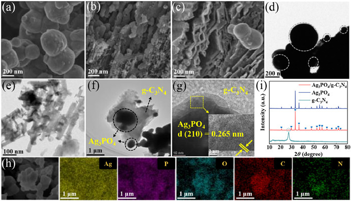
Scanning electron microscopy (SEM) and transmission electronic microscopy (TEM) were employed to analyze the morphological structure of the prepared samples. As can be seen in Fig. 1a, the prepared Ag3PO4 nanoparticles presented irregular spherical particles with diameters of about 200-700 nm and tendency to aggregate. From Fig. 1b, the g-C3N4 synthesized by melamine after secondary calcination condensation showed a thin porous lamellar structure. In addition, in the Ag3PO4/g-C3N4 composite (Fig. 1c), the dispersed Ag3PO4 particles were well adhered to the lamellar g-C3N4, which clearly displayed the tight connection between Ag3PO4 and g-C3N4 semiconductors. According to the TEM images (Figs. 1d-f), the aggregated particles of Ag3PO4 in Ag3PO4/g-C3N4 were successfully immobilized on the g-C3N4 crumpled sheets, while the direct contact existing between such heterojunctions facilitated the charge transfer [28]. In the HRTEM image of Ag3PO4/g-C3N4 (Fig. 1g), the lattice fringes spaced at 0.265 nm correspond to Ag3PO4 (210), and Ag3PO4 was in close contact with g-C3N4. Fig. 1h revealed the EDS spectrum of the composite with Ag, P, O, C and N uniformly distributed on Ag3PO4/g-C3N4.
Figure 1
Figure 1.
SEM image of (a) Ag3PO4, (b) g-C3N4, (c) Ag3PO4/g-C3N4. TEM image of (d) Ag3PO4, (e) g-C3N4 and (f) Ag3PO4/g-C3N4. (g) HRTEM image of Ag3PO4/g-C3N4 (Inset: the magnified image of Ag3PO4/g-C3N4). (h) Elemental mapping of Ag, P, O, C and N of Ag3PO4/g-C3N4 (SEM-EDS). (i) XRD patterns of the prepared photoanodes.
The physical phase and composition of the prepared samples were analyzed by x-ray diffraction (XRD). As shown in Fig. 1i, the clear diffraction peaks of Ag3PO4 indicated a high degree of crystallinity and its characteristic peaks were attributed to the cubic phase of Ag3PO4 (JCPDS No. 06-0505) [29]. All the characteristic peaks of Ag3PO4 crystals were located at 20.9°, 29.7°, 33.3°, 36.6°, 42.5°, 47.8°, 52.7°, 55.0°, 57.3°, 61.6°, 65.8°, 69.9°, 71.9°, and 73.9°, corresponding to (110), (200), (210), (211), (220), (310), (222), (320), (321), (400), (330), (420), (421), and (332) crystal planes, respectively. In the XRD pattern of g-C3N4, the diffraction peaks at 12.7° and 27.3° corresponded to the (100) and (002) facets of g-C3N4, respectively (JCPDS No.87-1526) [30]. The characteristic peaks of Ag3PO4 and g-C3N4 (Fig. S1 in Supporting information) could be observed in the XRD pattern of Ag3PO4/g-C3N4, which indicated that the Ag3PO4/g-C3N4 composites were successfully prepared. In addition, there are no characteristic peaks associated with metal Ag in any of the samples containing Ag3PO4, indicating that the prepared catalysts were not photocorroded.
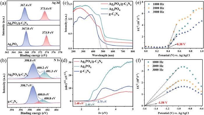
The surface elemental composition and electronic states of Ag3PO4/g-C3N4, Ag3PO4 and g-C3N4 photoanodes were characterized using XPS. XPS survey spectra of Ag3PO4/g-C3N4 showed the presence of Ag, P, O, C and N elements in the composite photoanodes (Fig. S2a in Supporting information). The peaks at binding energies of 367.8 and 373.9 eV in Fig. 2a corresponded to Ag 3d5/2 and Ag 3d3/2, respectively. The peak observed in the XPS spectrum of P 2p (Fig. S2b in Supporting information) appeared at 132.9 eV, which belonged to P5+. The two peaks at 530.5 eV and 532.4 eV in the spectrum of O 1s (Fig. S2c in Supporting information) could be ascribed to the O2- in metal-oxygen bonds and surface hydroxyl groups. The peaks at 287.2 and 288.3 eV in the C 1s spectrum (Fig. S2d in Supporting information) could be assigned to the C-N and C-N=C bonds in g-C3N4, while the peak at 284.8 eV was used to calibrate the other characteristic peaks [31]. Similarly, the peaks at 398.7, 400.0 and 400.8 eV of the N 1s spectrum in Fig. 2b represented the characteristic peaks of C-N=C, N-(C)3 and C-N-H in g-C3N4 [32]. Notably, the XPS spectra of Ag 3d, P 2p and O 1s of Ag3PO4/g-C3N4 showed negative shifts compared to Ag3PO4. The peaks of C 1s and N 1s in Ag3PO4/g-C3N4 were shifted towards higher binding energies compared to g-C3N4, suggesting that the formation of heterojunction resulted in a change of electron density between Ag3PO4 and g-C3N4. The above results revealed that electron transfer produced a directional interfacial electric field (IEF) from g-C3N4 to Ag3PO4 when g-C3N4 was in contact with Ag3PO4, which also led to energy band bending at the interface [33].
Figure 2
Figure 2.
The high-resolution XPS spectra of the prepared samples: (a) Ag 3d, (b) N 1s. (c) UV-vis DRS spectra and (d) Tauc images of different photoanodes. Mott-Schottky plots of (e) Ag3PO4 and (f) g-C3N4.
The light absorption properties of the prepared photoanodes were investigated by UV-vis DRS spectra. As shown in Fig. 2c, the light absorption edge of pure g-C3N4 was around 480 nm. Both Ag3PO4 and Ag3PO4/g-C3N4 composites showed strong absorption in both UV and visible wavelength ranges up to about 540 nm, suggesting that the Ag3PO4/g-C3N4 photoanode could effectively capture visible light. According to the Kubelka-Munk equation, the energy band gap (Eg) of Ag3PO4 and g-C3N4 were obtained to be 2.46 eV and 2.75 eV, respectively (Fig. 2d) [34]. The reduced band gap of Ag3PO4/g-C3N4 (2.48 eV) was more favorable for photoelectron leaps compared with g-C3N4. In addition, the positive slope of the Mott-Schottky curves (Figs. 2e and f) indicated that Ag3PO4 and g-C3N4 were characterized by n-type semiconductors, and the flat band (FB) potentials obtained by computational fitting were 0.58 eV (vs. NHE) and -1.38 eV (vs. NHE), respectively. For the n-type semiconductor, the conduction band (CB) potential is about 0.1 V negative than the flat band potential [35]. Therefore, the CB positions of Ag3PO4 and g-C3N4 were 0.48 eV (vs. NHE) and -1.48 eV (vs. NHE), respectively. According to the equation EVB = ECB + Eg, the valence band (VB) values of Ag3PO4 and g-C3N4 were 2.94 eV (vs. NHE) and 1.27 eV (vs. NHE), respectively [36]. According to the above results, the energy band arrangements of Ag3PO4 and g-C3N4 are staggered and fulfill the prerequisites for the construction of S-scheme heterojunctions.
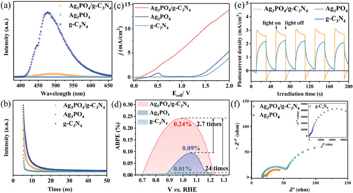
As shown by photoluminescence (PL) spectra in Fig. 3a, the pure g-C3N4 showed a strong emission peak around 475 nm, the higher emission intensity indicated the low separation efficiency of photoexcited carriers and the high rate of recombination [37]. In contrast, the peak intensity of Ag3PO4/g-C3N4 was significantly reduced due to the non-emission of Ag3PO4, indicating that the heterojunction effectively inhibited the recombination of carriers. In addition, time-resolved photoluminescence (TRPL) spectra analyzed the carrier separation behavior, employing a triple-exponential curve as the model function to fit the signal of decay profiles (Fig. 3b) [38]. The τav (average lifetimes) for Ag3PO4/g-C3N4, Ag3PO4 and g-C3N4 were 14.17, 17.05 and 14.71 ns, respectively (Table S1 in Supporting information). The shortening of the photoexcited charge lifetimes is associated with the facilitation of electron transfer, suggesting that the reduction of carrier lifetimes in Ag3PO4/g-C3N4 may be due to the S-scheme heterojunction that maximize the separation efficiency of the photogenerated carriers [39]. The following photoelectrochemical tests further validated the efficient charge transfer and separation of the materials. The linear sweep voltammetry (LSV) of the photoanode was tested under light conditions as shown in Fig. 3c. At the same current density, the required voltage of the Ag3PO4/g-C3N4 photoanode was significantly smaller than that of the Ag3PO4 and g-C3N4 photoanodes, indicating that the reaction kinetics at the interface of the two semiconductors after the formation of the heterojunction was optimized and the interfacial carrier transfer was effectively promoted. The applied bias photon-to-current efficiency (ABPE) of Ag3PO4/g-C3N4, Ag3PO4 and g-C3N4 calculated by Eq. S1 (Supporting information) were 0.24% (1.00 V vs. RHE), 0.09% (1.06 V vs. RHE) and 0.01% (0.94 V vs. RHE), respectively (Fig. 3d). Ag3PO4/g-C3N4 exhibited the highest ABPE among all photoanodes, which was 2.7 and 24.0 times that of Ag3PO4 and g-C3N4, respectively. Indirectly, it was demonstrated that the construction of heterojunction significantly inhibited the electron and hole complexation. In addition, it also illustrated the potential optimal photoelectric conversion efficiency of Ag3PO4/g-C3N4 photoanode [40]. The transient photocurrent response was recorded under intermittent light as shown in Fig. 3e and Fig. S3 (Supporting information). Ag3PO4/g-C3N4 had the highest photocurrent response, which significantly exceeded that of Ag3PO4 and g-C3N4. From the electrochemical impedance spectroscopy (EIS) in Fig. 3f, it could be seen that the semicircle radius of the Nyquist plots of the Ag3PO4/g-C3N4 photoanode was smaller than those of the bare Ag3PO4 and g-C3N4 photoanodes, which suggested that the construction of the Ag3PO4/g-C3N4 heterojunction effectively reduced the charge transfer resistance. Evidently, the radius of the semicircle of the Nyquist plot under light conditions was significantly smaller than that under dark conditions, indicating that light significantly improved the charge transfer properties (Fig. S4 in Supporting information). The above photoelectrochemical tests demonstrated that the constructed Ag3PO4/g-C3N4 heterojunction enhanced the photocatalytic activity compared with the pristine samples, which led to a better removal of TC.
Figure 3
Figure 3.
(a) Photoluminescence (PL) spectra, (b) time-resolved photoluminescence (TRPL) spectra, (c) linear sweep voltammetry (LSV) curves, (d) applied bias photon-to-current efficiency (ABPE) values, (e) transient photocurrent responses, (f) electrochemical impedance spectroscopy (EIS) spectra under the light condition of the as-prepared samples.
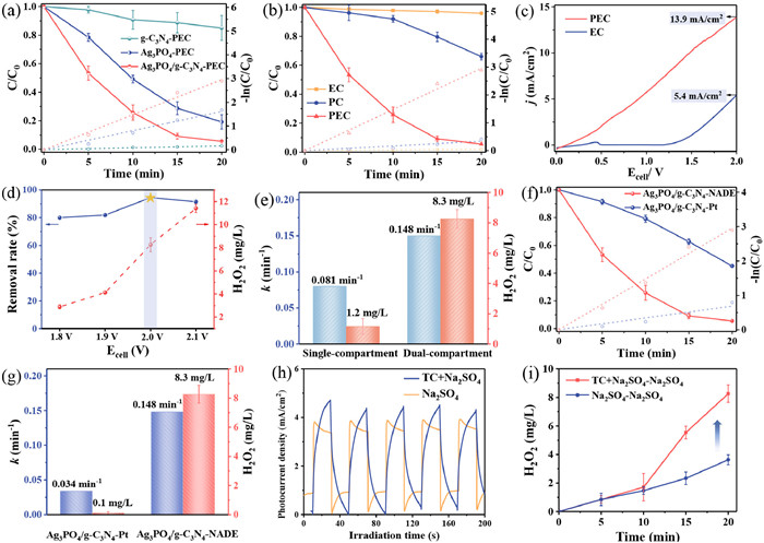
The degradation and H2O2 production properties of the prepared photoanode coupled with NADE cathode PEC system were investigated using TC as the target pollutant at 2.0 V cell voltage. As shown in Fig. 4a, the corresponding TC removal efficiencies of Ag3PO4/g-C3N4, Ag3PO4, and g-C3N4 photoanodes were 94.5%, 80.8%, and 15.0%, respectively, after 20 min of irradiation with LED light. The PEC degradation of TC conformed to the pseudo-first-order kinetics, and the rate constants of Ag3PO4/g-C3N4 photoanode (0.148 min-1) was 1.8 and 18.5 times that of Ag3PO4 (0.081 min-1) and g-C3N4 (0.008 min-1), respectively. Apparently, the Ag3PO4/g-C3N4 heterojunction photoanode showed a significant advantage in PEC degradation of TC compared to pure Ag3PO4 and g-C3N4. This enhancement may be based on the interfacial interaction of the S-scheme heterojunction which improved the efficiency of photogenerated carrier separation and thus enhanced the PEC performance [41]. This result is consistent with the conclusions drawn from the photoelectrochemical tests in Fig. 3.
Figure 4
Figure 4.
The PEC degradation rate and pseudo-first-order kinetic curves of TC with (a) different photoanodes and (b) reaction systems. (c) LSV curves of EC and PEC system. (d) Effect of different applied cell voltage on TC removal and H2O2 production in Ag3PO4/g-C3N4-NADE PEC system. Degradation rate constant and H2O2 production in (e) single-compartment or dual-compartment reactor, and (f) Ag3PO4/g-C3N4-NADE or Ag3PO4/g-C3N4-Pt PEC system. (g) Photocurrent density and (h) H2O2 production in TC-present and TC-absent PEC systems. (i) Comparison of contaminant removal performance of other reported photoanodes at applied cell voltages of 2.0 V or higher.
In addition, the performance of Ag3PO4/g-C3N4 electrode was also explored in PC and EC systems. As can be seen from Fig. 4b, the removal of TC by EC (4.1%) was negligible after 20 min of reaction, while the degradation efficiency of the PC was only 34.1%. In contrast, the removal efficiency of the PEC system reached 94.5%, while the rate constant for TC degradation by PEC (0.148 min-1) was 8.7 and 74.0 times that of PC (0.017 min-1) and EC (0.002 min-1), respectively. Therefore, the synergy factor (SF) of PC and EC in the PEC system was calculated to be 6.8 by Eq. 1, where kPEC, kPC and kEC are the degradation rate constants by PEC, PC and EC processes, respectively [42]. The high synergy factor indicated that the applied voltage could promote the separation and transfer of carriers on the photoanode, which improved the TC removal efficiency in the PEC system. Furthermore, it can be visualized from Fig. 4c that the synergistic effect of the PC and EC process resulted in a higher current density for this PEC system, 2.6 times that of EC, at a cell voltage of 2.0 V.
SF=kPECkEC+kPC−1
(1)
The effects of different applied cell voltages on water purification and H2O2 production in the PEC system were further investigated (Fig. 4d). When the applied cell voltage was increased from 1.8 V to 2.0 V, the TC removal efficiency increased from 80.0% to 94.5%, while the H2O2 production was enhanced from 2.9 mg/L (1.5 µmol-1 h-1 cm-2) to 8.3 mg/L (4.3 µmol-1 h-1 cm-2), after 20 min of irradiation with LED light. When the applied cell voltage was further increased to 2.1 V, the TC degradation efficiency showed a decreasing trend (91.5%), suggesting that the photogenerated h+ may trigger the side reaction oxygen evolution reaction, which inhibited the visible absorption and affected the ROS production [43]. Therefore, 2.0 V was selected as the optimal applied cell voltage for TC degradation and H2O2 production by this PEC system. Intriguingly, the Ag3PO4/g-C3N4 photoanode coupled with NADE cathode system drastically reduced both TC degradation performance (0.081 min-1) and H2O2 yield (1.2 mg/L) when operated in a single-compartment reactor. It may be because the H2O2 produced by the cathode in the single-compartment reactor was easily decomposed by the Ag3PO4/g-C3N4 photoanode, which severely reduced the total H2O2 yield (Fig. 4e). In addition, H2O2 is highly susceptible to react with holes produced by the photoanode to form O2 and H2O thereby hindering the removal of TC [23]. Therefore, the construction of a suitable dual-compartment reactor is necessary for PEC water purification coupled with H2O2 production.
Considering the coupling of photoanode water purification and cathode H2O2 production, PEC systems with different cathodes and different reaction solution systems were constructed. The performance of the Ag3PO4/g-C3N4-NADE PEC system was compared with that of Ag3PO4/g-C3N4-Pt (conventional PEC system) for the degradation of TC. Notably, the TC degradation efficiency of Ag3PO4/g-C3N4-Pt PEC system only reached 54.9% (Fig. 4f), and the rate constant of TC degradation by the Ag3PO4/g-C3N4-NADE PEC system was 4.4 times that of Ag3PO4/g-C3N4-Pt PEC system (0.034 min-1) (Fig. 4g). The above results indicated that to achieve the same water purification effect, the Ag3PO4/g-C3N4-NADE PEC system required less reaction time, which highlighted the obvious performance advantage. Concurrently, the H2O2 yield of Ag3PO4/g-C3N4-NADE PEC reached 8.3 mg/L, while the H2O2 yield of Ag3PO4/g-C3N4-Pt PEC system was negligible (Fig. 4g). Importantly, the hydrophobic and porous structure of NADE enabled the natural diffusion of molecular oxygen from the air to the reaction interface and provided sufficient active sites for the two-electron ORR process without any aeration energy consumption [26]. In addition, the addition of TC to the Na2SO4 solution in the anode chamber increased the photocurrent density of the PEC system, as shown in Fig. 4h. It can be inferred that the PEC system could operate more efficiently by replacing the water oxidation at the anode with TC degradation. This inference could be further verified by the effect of different anodic reaction solutions on cathodic H2O2 generation in Fig. 4i. It was obvious that the production of H2O2 in the cathode chamber of the PEC system in the presence of TC (4.3 µmol-1 h-1 cm-2) was 2.3 times that of absence of TC (1.9 µmol-1 h-1 cm-2). Moreover, the current efficiency (Eq. S2 in Supporting information) of H2O2 production in the PEC system with the presence of TC (78.6%) was much higher than that of the system without TC (34.0%). This indicated that the removal of TC had a significant contribution on H2O2 production, in which photoelectrons from the TC degradation process were efficiently transferred to the cathode for H2O2 production [44]. The above results demonstrated that the Ag3PO4/g-C3N4-NADE PEC system achieved efficient PEC water purification and H2O2 value-added with the coupling effects of both cathode and anode. This system was compared in the literature with other systems for simultaneous removal of pollutants and H2O2 production, and the degradation performance of the Ag3PO4/g-C3N4 photoanode was particularly impressive (Table S2 in Supporting information). However, the H2O2 production rate needs to be further improved. Moreover, the contaminant removal performance was compared with that of previously reported photoanodes at an applied cell voltage of 2.0 V or higher. Comparison of the reaction rate constants showed that the Ag3PO4/g-C3N4-NADE PEC system obtained better water treatment performance than other photoanodes at 2.0 V applied cell voltage (Table S3 in Supporting information). In addition, the system had the advantage of adding value to chemical (H2O2).
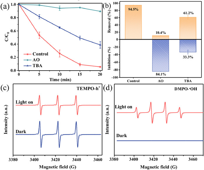
In the anodic chamber of the PEC system, the pollutant removal pathways are usually direct hole oxidation and indirect •OH oxidation. To explore the main active species of the PEC system, the degree of inhibition of TC degradation was evaluated by the addition of ammonium oxalate (AO) and tert-butanol (TBA). As shown in Figs. 5a and b, the inhibition of PEC degradation was 84.1% after the addition of AO to the solution, suggesting that h+ was the main active species for TC degradation. Meanwhile, TBA (33.3%) also inhibited the PEC system, indicating that •OH also played an important role in TC degradation.
Figure 5
Figure 5.
(a) Degradation performance, (b) removal and inhibition rate of TC on Ag3PO4/g-C3N4 photoanode with different scavenger. ESR spectra of (c) TEMPO-h+ and (d) DMPO-•OH under dark and LED-light irradiation.
In addition, to further verify the free radical production, electron spin resonance (ESR) analysis was performed on Ag3PO4/g-C3N4 photoanode using spin trapping reagents. In Fig. 5c, there were three strong signal peaks (1:1:1) under dark conditions, while the intensity of the signal peaks decreased significantly under light for 20 min [45]. This was attributed to the reaction of TEMPO with h+ to form spin-adducts, which attenuated the h+ signal peak, indicating that photogenerated h+ was produced during Ag3PO4/g-C3N4 PEC [46,47]. In addition, no •OH signal peaks appeared under dark conditions, whereas the •OH (1:2:2:1) signal peak could be clearly observed after light exposure (Fig. 5d). These conclusions were consistent with the results of free radical capture experiments that h+ and •OH could be produced as the main active species involved in TC degradation during the PEC reaction.
Furthermore, as seen from Figs. 2c-f, the interleaved energy band structures of g-C3N4 and Ag3PO4 can constitute type Ⅱ heterojunctions or S-scheme heterojunctions. However, the VB of g-C3N4 (1.27 eV (vs. NHE)) in type Ⅱ heterojunctions could not reach the conditions for the production of •OH (E (•OH/OH-) = +1.99 eV vs. NHE; E (•OH/H2O) = +2.27 V vs. NHE) [48]. The above findings are inconsistent with Figs. 5a and b and the ESR test results, proving that the heterojunction type was not a type Ⅱ heterojunction.
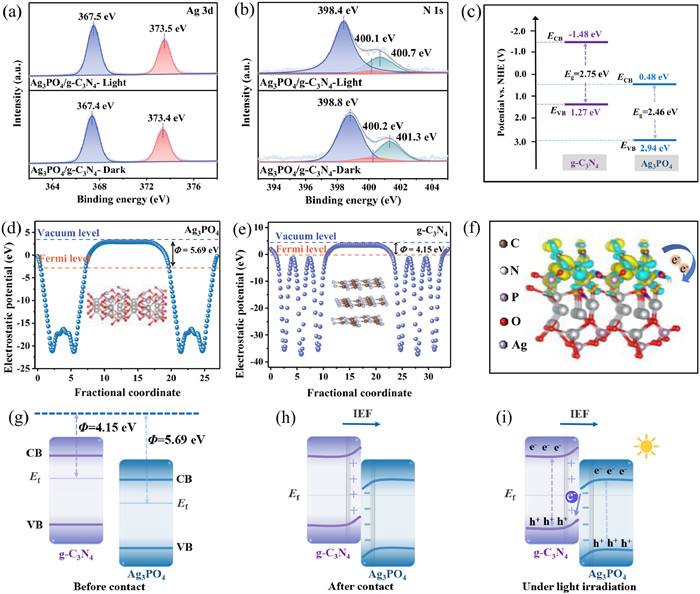
Additionally, the reaction mechanism of Ag3PO4/g-C3N4 materials was further analyzed by in-situ irradiation XPS spectroscopy. Compared with Ag3PO4/g-C3N4 in the dark, the binding energies of Ag 3d, P 2p, and O 1s significantly moved toward higher energy levels under light (Fig. 6a and Figs. S5a and b in Supporting information). While the N 1s and C 1s were significantly shifted toward the lower energy levels (Fig. 6b and Fig. S5c in Supporting information). Thus, these results suggested that the photogenerated electrons of Ag3PO4/g-C3N4 were spontaneously transferred from Ag3PO4 to g-C3N4 under light irradiation [49].
Figure 6
Figure 6.
High-resolution XPS spectra of (a) Ag 3d and (b) N 1s of Ag3PO4/g-C3N4 under dark and light conditions. (c) Band structures of Ag3PO4 and g-C3N4. Calculated the electrostatic potential for the (210) face of (d) Ag3PO4 and (002) face of (e) g-C3N4 surfaces. (f) Charge density difference at Ag3PO4/g-C3N4 interface. (g-i) Schematic illustration of Ag3PO4/g-C3N4 S-scheme heterojunction.
Based on the results of UV-vis DRS spectra and Mott-Schottky tests, Ag3PO4 and g-C3N4 presented a staggered band diagram (Fig. 6c), which is one of the necessary conditions for the construction of S-scheme heterojunctions [50]. To further analyze the charge transfer mechanism of Ag3PO4/g-C3N4, DFT calculations were performed. Calculations yielded 5.69 eV and 4.15 eV for the work functions of Ag3PO4 (Fig. 6d) and g-C3N4 (Fig. 6e), respectively, and the Fermi level (Ef) of g-C3N4 was higher than that of Ag3PO4 (Fig. 6g). The contact between the two promoted electron transfer from g-C3N4 to Ag3PO4 until the same Ef was reached at the interface (Fig. 6h). The above electron transfer produced an interfacial electric field (IEF) from g-C3N4 to Ag3PO4 and led to energy band bending at the interface, which is consistent with the XPS results. Further, the charge density difference at the Ag3PO4/g-C3N4 interface was also simulated (Fig. 6f). The calculations showed that g-C3N4 lost electrons and transferred them to the Ag3PO4 interface, thus forming a built-in electric field from g-C3N4 to Ag3PO4 at the interface. Under illumination, the g-C3N4 and Ag3PO4 semiconductors were excited to produce photogenerated electrons and holes. Under the action of IEF and bending band, the photogenerated electrons in the CB of Ag3PO4 rapidly recombined with the holes in the VB of g-C3N4 (Fig. 6i), which is consistent with the findings with in-situ irradiation XPS spectroscopy (Figs. 6a and b and Fig. S5a-c). In addition, the holes in the VB of Ag3PO4 and electrons in the CB of g-C3N4 with strong redox capacity were retained for participating in the reaction. Thus, the charge transfer pathway of the Ag3PO4/g-C3N4 heterojunction followed the S-scheme mechanism.
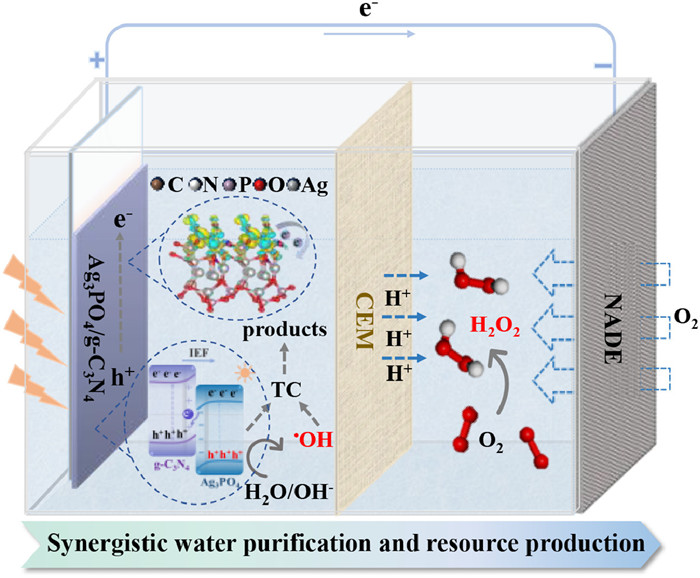
On these bases, the reaction mechanism of TC degradation and H2O2 generation by Ag3PO4/g-C3N4-NADE PEC system was proposed (Fig. 7). In the presence of Ag3PO4/g-C3N4 S-scheme heterojunction photoanode, the holes of Ag3PO4 with strong oxidizing ability and the •OH produced by its oxidation of OH-/H2O were used for TC degradation. Meanwhile, under the combined effect of applied voltage and S-scheme heterojunction, the electrons of Ag3PO4/g-C3N4 photoanode were transferred to NADE, participating in the production of H2O2 while increasing the carrier separation rate. In addition, NADE allows oxygen to naturally diffuse into the reaction interface without the need for gas explosion and participate in the reduction reaction to produce H2O2. Thus, the Ag3PO4/g-C3N4-NADE PEC system achieves efficient water purification and value-added chemicals with the coupling of cathode and anode.
Figure 7
Figure 7.
Schematic illustration of Ag3PO4/g-C3N4-NADE PEC system.
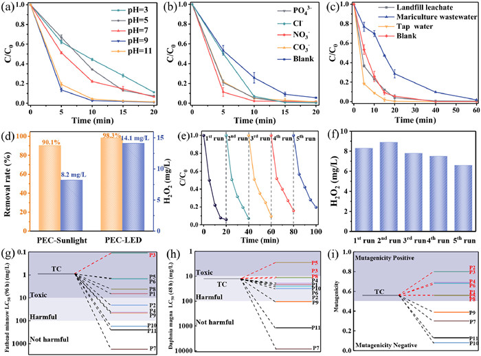
The effect of pH on the degradation performance of TC in this PEC system was investigated. As shown in Fig. 8a, the PEC system essentially achieved more than 90% removal over a wide pH range from 3 to 11, within 20 min reaction. The highest degradation efficiency of TC was observed at pH 9 and pH 11, which was attributed to the alkaline conditions that promoted the photolysis of TC [51]. This indicated that the Ag3PO4/g-C3N4 photoanode effectively overcame the pH limitation and maintained high activity.
Figure 8
Figure 8.
PEC degradation of TC at different (a) initial pH values, (b) co-existing anions and (c) water source. (d) Ag3PO4/g-C3N4-NADE PEC system performance under different light condition for 30 min. Recycling tests of (e) TC degradation and (f) H2O2 production. (g) Fathead minnow LC50-96 h, (h) daphnia magna LC50-48 h and (i) mutagenicity of TC and its possible degradation intermediates via T.E.S.T. PEC-Sunlight system under real sunlight in summer from 12:00-14:00 (Tianjin, China).
The effects of widely available anions (NO3-, CO32-, PO43-, Cl-) on TC degradation by PEC were investigated based on the composition of the actual water body. The anions concentration introduced were 10 mmol/L (Fig. 8b). Interestingly, the addition of all four anions promoted the PEC reaction activity, achieving more than 98% TC removal within 20 min. From Fig. 8a, the initial pH of the PEC reaction system was more favorable for TC degradation under alkaline conditions. Therefore, the pH of the PEC system with the addition of NO3-, CO32-, PO43-, and Cl- was determined to be 6.2, 10.3, 11.3, and 6.6, respectively. Obviously, the changes in pH caused by the addition of CO32- and PO43- were more favorable for TC removal. In addition, the addition of Cl- increased the TC degradation efficiency from 0.148 min-1 to 0.266 min-1, probably because h+ and •OH can be captured by Cl- and reacted to form reactive chlorine species, which enhanced the PEC performance [52]. Unexpectedly, the introduction of NO3- had an excellent accelerating effect on the reaction, which can be explained by the activation of NO3- to form NO2• and •OH under light conditions, thus increasing the removal of TC [53]. In addition, the removal of TC reached more than 90% at initial concentrations of 10-50 mg/L (Fig. S6 in Supporting information). When the TC concentration was increased from 20 mg/L to 50 mg/L, the TC removal efficiency slightly decreased. However, under lower concentration conditions (10 mg/L), the removal performance of TC was lower than that at 20-30 mg/L. In fact, the number of pollutants adsorbed on the surface of the photoanode increased with the increases in concentration, but excessively high concentrations reduce the generation of active substances [53]. Additionally, to determine the efficacy of the electrode in these different environments, we evaluated the performance of the Ag3PO4/g-C3N4-NADE PEC system for the degradation of TCs in different real water samples with the water quality parameters detailed in Table S4 (Supporting information). As shown in Fig. 8c, the Ag3PO4/g-C3N4-NADE PEC system exhibited excellent performance in removing TC in tap water, landfill leachate and mariculture wastewater, with removal rates of 100.0%, 99.5% and 98.2%, respectively, after 60 min of reaction.
In addition, the applicability of the Ag3PO4/g-C3N4-NADE PEC system under different light conditions was explored. As shown in Fig. 8d, when the reaction time was extended to 30 min, the PEC system under sunlight irradiation (PEC-Sunlight) degraded TC up to 90.1% in the anode chamber, and the H2O2 yield reached 8.2 mg/L in the cathode chamber. Under LED light irradiation (PEC-LED), the TC removal efficiency was 98.3%, and the H2O2 yield was 14.1 mg/L. The TC removal performance of the PEC-Sunlight (k = 0.071 min-1) system was lower than that of the LED lamp irradiation condition (PEC-LED, k = 0.148 min-1) in Fig. S7 (Supporting information). The main reason was that the optical density parameter of the PEC-Sunlight system (0.042 W/cm2) was much smaller than that of the PEC-LED (0.135 W/cm2) system. Nevertheless, the Ag3PO4/g-C3N4-NADE PEC system was able to achieve efficient wastewater purification and H2O2 production under both LED and sunlight irradiation.
Furthermore, to evaluate the application potential of the Ag3PO4/g-C3N4-NADE PEC system, the stability over multiple use cycles was investigated. As shown in Figs. 8e and f, the PEC activity of Ag3PO4/g-C3N4 photoanode for TC degradation remained above 80% after five cycles. The NADE cathode produced H2O2 yields of 8.3, 8.9, 7.8, 7.5, and 6.6 mg/L, respectively, with small fluctuations in performance. It was shown that the Ag3PO4/g-C3N4-NADE PEC system could maintain good stability in simultaneous TC removal and H2O2 generation. To further analyze the reason for the slight decrease in PEC performance after five cycle experiments, we compared the XRD of Ag3PO4/g-C3N4 before and after photoanodic reaction (Fig. S8 in Supporting information). Weaker diffraction peaks appeared at 38.0°, 44.3° and 64.4° for Ag3PO4/g-C3N4 after the reaction, which belonged to the (111), (200) and (220) crystal planes of Ag nanoparticles, respectively (JCPDS: 04-0783) [54]. The extra diffraction peaks were caused by photo-corrosion of Ag3PO4 under light illumination [55]. Nevertheless, the charge transfer mechanism of the S-scheme heterojunction promoted carrier separation and slowed down the photo-corrosion of Ag+, improving the activity and stability of the Ag3PO4/g-C3N4 photoanode. In future studies, further inhibition of photo-corrosion of Ag3PO4 will be considered through the addition of a surface protective layer or crystal surface modulation [56].
To reveal the possible degradation process of TC in Ag3PO4/g-C3N4-NADE PEC system, the intermediates were identified by LC-MS and the mass spectra were shown in Fig. S9 (Supporting information). Based on the analysis, three possible TC degradation pathways were given in Fig. S10 (Supporting information). In pathway I, TC (m/z 445) was oxidized to P1 (m/z 460) by dihydroxy addition reaction in the presence of h+ and •OH [51]. Subsequently, P1 was converted to P6 (m/z 290) and P8 (m/z 246) by reactions such as deamination, demethylation, and ring-opening. In pathway Ⅱ, TC was oxidized to P3 (m/z 415), P5 (m/z 318), and P9 (m/z 113) in the presence of free radicals via demethylation, dehydroxylation, and ring-opening reactions. In pathway Ⅲ, TC further formed to P2 (m/z 453), P4 (m/z 338), and P7 (m/z 274) by demethylation, deamidation, and ring-opening. Ultimately, the intermediates were oxidized to P10 (m/z 117) and P11 (m/z 89) and further mineralized to CO2 and H2O.
Based on quantitative structure-activity relationship (QSAR) model, the acute toxicity and mutagenicity of TC and intermediates were evaluated using Toxicity Estimation Software Tool (T.E.S.T.) software [51]. As shown in Fig. 8g, the LC50 (96 h) of TC for fathead minnow was 0.90 mg/L, and the toxicity of the intermediates was lower than that of TC except for intermediate P3. In addition, the LC50 (48 h) of TC and intermediates (except P5) were higher than 10 mg/L, which was "harmful" for daphnia magna, and even "no harmful" for P7, P9 and P11 (Fig. 8h). Furthermore, the mutagenicity of TC was higher than 0.5, and the mutagenicity was "positive" (Fig. 8i) [57]. While the mutagenicity of P1-P6 and P8 was "positive", their subsequent degradation products P7 and P9-P11 had negative mutagenicity. The above predictions indicated that degradation of TC in Ag3PO4/g-C3N4-NADE PEC system could effectively attenuate the environmental risk.
In summary, an Ag3PO4/g-C3N4 S-scheme heterojunction photoanode was successfully prepared, and a PEC system consisting of this photoanode and NADE was constructed. Compared with the conventional Ag3PO4/g-C3N4-Pt PEC system, the new Ag3PO4/g-C3N4-NADE PEC system had obvious performance advantages. After LED lamps irradiation for 20 min, the rate constant of TC degradation by the Ag3PO4/g-C3N4-NADE PEC system (0.148 min-1) was 4.4 times that of Ag3PO4/g-C3N4-Pt PEC system (0.034 min-1) under 2.0 V cell voltage. And the H2O2 yield under NADE was 4.3 µmol-1 h-1 cm-2. The degradation rate constant (0.148 min-1) of the PEC system for TC was higher than that of PC (0.017 min-1) and EC (0.002 min-1), respectively. The calculated SF in the PEC system was 6.8. Additionally, based on the synergistic interaction between the Ag3PO4/g-C3N4 S-scheme heterojunction photoanode and cathode, the photoelectrons were efficiently transferred to the cathode to produce H2O2. The current efficiency of H2O2 production in the PEC system with the presence of TC (78.6%) was much higher than that of the system without TC (34.0%). The removal of TC in this PEC system had a significant contribution on H2O2 production. The quenching experiments and ESR test results showed that the active substances playing a major role in this PEC system were mainly h+ followed by •OH. The DFT calculations showed that there was an interface interaction between g-C3N4 and Ag3PO4 and Ag3PO4/g-C3N4 photoanode was more favorable for organic pollutant adsorption. In addition, efficient TC removal and H2O2 production could still be achieved by using actual sunlight. This study provides an effective strategy for constructing a PEC system with an S-scheme heterojunction photoanode coupled to a NADE cathode to maximize the utilization of the electrodes.
Declaration of competing interest
The authors declare that they have no known competing financial interests or personal relationships that could have appeared to influence the work reported in this paper.
M. Liu, W. Yang, R. Xiao, et al., Angew. Chem. Int. Ed. 63 (2024) 202407481. doi: 10.1002/anie.202407481
[50]
Y. Yang, J. Liu, M. Gu, et al., Appl. Catal. B: Environ. 333 (2023) 122780.
[51]
X. Hu, Z. Zhang, P. Lu, et al., Water Res 260 (2024) 121936.
[52]
M.S. Koo, X. Chen, K. Cho, et al., Environ. Sci. Technol. 53 (2019) 9926–9936. doi: 10.1021/acs.est.9b02401
[53]
H. Wu, J. Jing, S. Li, et al., Appl. Catal. B: Environ. 360 (2025) 124517.
[54]
S. Li, M. Zhang, Z. Qu, et al., Chem. Eng. J. 382 (2020) 122394.
[55]
W. Kong, L. Huang, X. Quan, et al., Appl. Catal. B: Environ. 284 (2021) 119696.
[56]
J. Sun, C. Fu, Z. Hu, et al., Crit. Rev. Environ. Sci. Technol. 55 (2025) 783–804. doi: 10.1080/10643389.2025.2450128
[57]
S. Xin, S. Huo, C. Zhang, et al., Appl. Catal. B: Environ. 305 (2022) 121024.
Figure 1
SEM image of (a) Ag3PO4, (b) g-C3N4, (c) Ag3PO4/g-C3N4. TEM image of (d) Ag3PO4, (e) g-C3N4 and (f) Ag3PO4/g-C3N4. (g) HRTEM image of Ag3PO4/g-C3N4 (Inset: the magnified image of Ag3PO4/g-C3N4). (h) Elemental mapping of Ag, P, O, C and N of Ag3PO4/g-C3N4 (SEM-EDS). (i) XRD patterns of the prepared photoanodes.
Figure 2
The high-resolution XPS spectra of the prepared samples: (a) Ag 3d, (b) N 1s. (c) UV-vis DRS spectra and (d) Tauc images of different photoanodes. Mott-Schottky plots of (e) Ag3PO4 and (f) g-C3N4.
Figure 4
The PEC degradation rate and pseudo-first-order kinetic curves of TC with (a) different photoanodes and (b) reaction systems. (c) LSV curves of EC and PEC system. (d) Effect of different applied cell voltage on TC removal and H2O2 production in Ag3PO4/g-C3N4-NADE PEC system. Degradation rate constant and H2O2 production in (e) single-compartment or dual-compartment reactor, and (f) Ag3PO4/g-C3N4-NADE or Ag3PO4/g-C3N4-Pt PEC system. (g) Photocurrent density and (h) H2O2 production in TC-present and TC-absent PEC systems. (i) Comparison of contaminant removal performance of other reported photoanodes at applied cell voltages of 2.0 V or higher.
Figure 5
(a) Degradation performance, (b) removal and inhibition rate of TC on Ag3PO4/g-C3N4 photoanode with different scavenger. ESR spectra of (c) TEMPO-h+ and (d) DMPO-•OH under dark and LED-light irradiation.
Figure 6
High-resolution XPS spectra of (a) Ag 3d and (b) N 1s of Ag3PO4/g-C3N4 under dark and light conditions. (c) Band structures of Ag3PO4 and g-C3N4. Calculated the electrostatic potential for the (210) face of (d) Ag3PO4 and (002) face of (e) g-C3N4 surfaces. (f) Charge density difference at Ag3PO4/g-C3N4 interface. (g-i) Schematic illustration of Ag3PO4/g-C3N4 S-scheme heterojunction.
Figure 8
PEC degradation of TC at different (a) initial pH values, (b) co-existing anions and (c) water source. (d) Ag3PO4/g-C3N4-NADE PEC system performance under different light condition for 30 min. Recycling tests of (e) TC degradation and (f) H2O2 production. (g) Fathead minnow LC50-96 h, (h) daphnia magna LC50-48 h and (i) mutagenicity of TC and its possible degradation intermediates via T.E.S.T. PEC-Sunlight system under real sunlight in summer from 12:00-14:00 (Tianjin, China).

 DownLoad:

 下载:
下载:


 下载:
下载:
