Received Date:
16 April 2025 Accepted Date:
11 September 2025 Revised Date:
09 September 2025 Available Online:
15 January 2026
Abstract:
Conversion of ammonia into hydrogen, a crucial pathway for the hydrogen economy, is severely constrained by the intricacy of the required equipment and the low efficiency. Herein, Pd@PtNiCoRuIr core-shell mesoporous bifunctional electrocatalysts were fabricated via a one-step wet-chemical reduction approach. By utilizing the limiting effect of triblock copolymers, gradient distribution control of six metal elements (Pd core and Pt/Ni/Co/Ru/Ir high-entropy alloys shell) was achieved, where the high-entropy alloy shell forms high-density active sites through lattice distortion effect. With the help of lattice distortion and mesoporous-confinement-enabled interfacial coupling effects, Pd@PtNiCoRuIr catalyst exhibited exceptional bifunctional performance in alkaline media: A low hydrogen evolution reaction (HER) overpotential of 30.5 mV at 10 mA/cm2 and a high ammonia oxidation reaction (AOR) peak current density of 19.6 mA/cm2 at 0.7 V vs. RHE, representing a 3.83-fold enhancement over commercial Pt/C. Moreover, a rechargeable Zn-NH3 battery system was constructed and achieved 92.3% Faradaic efficiency (FE) for NH3-to-H2 conversion with outstanding stability at 16 mA/cm2, thereby providing an innovative solution for efficient ammonia decomposition-based hydrogen production.
Development of sustainable energy systems relies heavily on efficient energy carriers capable of storage, transportation, and on-demand energy release [1-3]. Hydrogen emerges as a leading carbon-neutral candidate due to its exceptional gravimetric energy density and environmentally benign combustion profile [4-6]. However, practical implementation requires addressing storage and transport challenges, prompting exploration of hydrogen-rich compounds [7,8]. Ammonia stands out as a viable hydrogen vector, offering a high hydrogen mass fraction (17.7%), straightforward liquefaction at moderate pressures, and enhanced safety characteristics compared to pure hydrogen [9,10]. The key to the hydrogen economy framework is the optimization of ammonia conversion technologies. Although conventional thermal cracking methods, such as high-temperature catalytic decomposition, have been widely employed for hydrogen production via ammonia decomposition, they require operation at temperatures exceeding 800 ℃ under high-pressure conditions, resulting in high energy consumption, complex equipment configurations, and challenges in system miniaturization. Furthermore, the elevated temperatures promote catalyst sintering and deactivation, significantly compromising long-term system stability. Electrochemical ammonia decomposition presents a transformative alternative that demonstrates theoretical viability at ultralow voltage (0.077 V) under ambient operational parameters, thus presenting an energy-efficient pathway for hydrogen liberation from ammonia carriers [11-14]. Nevertheless, conventional ammonia electrolysis systems face inherent limitations from simultaneous cathodic hydrogen evolution reaction (HER) and anodic ammonia oxidation reaction (AOR) occurring in a single reaction chamber, leading to unavoidable cross-contamination of H2 and N2 products and complicating gas separation and system scalability [15-17]. In addition, the inherent kinetic limitations of AOR in comparison with HER critically constrain the anodic half-reaction electrolysis efficiency [18,19]. Therefore, designing an efficient ammonia decomposition electrolyzer system with isolated hydrogen production capacity is highly desirable [20].
Metal-catalysis battery, derived from Li-O2 battery designs, employs a metal anode and a catalytic cathode to temporally decouple redox reactions during discharge/charge cycles [21,22]. Then, the temporal decoupling separates discharge/charge products and enables electrical energy generation. Overall, in contrast to the conventional spatiotemporal decoupling via membranes or redox mediators, the metal-catalysis battery system relies on a bifunctional catalyst-mediated dual cathodic reaction mechanism, achieving physical separation of gaseous products through stepwise cathode redox processes [23,24]. Therefore, developing a metal-catalysis battery system to achieve efficient and isolated H2 recovery from NH3 represents a promising approach.
The rechargeable aqueous Zn-NH3 battery, powered by an AOR/HER bifunctional electrocatalyst enabling decoupled ammonia splitting, efficiently converts NH3 to H2 while generating electrical energy by transforming NH3 to N2 oxidation potential during charging and reducing H2O to H2 with power output during discharging [25]. In this loop, continuous and on-demand NH3-to-H2 conversion is achieved without further separation and purification, and the efficient process can be realized irrespective of kinetics mismatch through the temporal decoupling of AOR and HER. Notably, the AOR/HER bifunctional electrocatalyst is the prerequisite for driving the system. Nowadays, Pt and Pt-based alloys are still regarded as state-of-the-art catalysts for AOR due to the relative suitable bond strength of the *M-N [26,27]. Nevertheless, the performance is hindered by the adsorption of reactive nitrogen intermediates (Nads) on Pt surfaces [28,29]. Therefore, regulating the electronic structure of the catalyst surface is particularly important [30]. Recent studies have demonstrated that incorporating heteroatoms into noble metal-based catalysts can effectively modulate their electronic configuration and significantly enhance (electro)catalytic efficiency [31,32]. Furthermore, mesostructured architectures exhibit superior activity compared to conventional bulk nanoparticles (NPs) systems, owing to their augmented specific surface areas and maximized exposure of reactive sites [33,34]. However, most reported Pt-based mesoporous alloys are limited to binary or ternary systems, which suffer from insufficient active-site density and structural durability [35,36]. Very recently, researchers found that high-entropy alloys (HEAs), especially with rich lattice distortion, caused by constituent elements with varying atomic sizes, could exhibit unique mechanical properties and tunable electronic structures [37,38]. Furthermore, the morphology of NPs in terms of size, shape, and surface energy plays an important role in improving functionality and activity [39]. Wherein, core-shell configuration has been corroborated as a successful approach in optimizing the catalytic activity [40,41]. Therefore, integrating the advantageous features of HEA-including rich lattice distortion, mesoporous architectures, and core-shell configurations-provides a strategic avenue to elucidate their synergistic effects on catalytic behavior. However, polymetallic reduction kinetics disparities and lattice mismatch severely impede the successful construction of mesoporous HEA-based core-shell AOR/HER bifunctional electrocatalyst [42].
Herein, a core-shell-structured Pd@PtNiCoRuIr mesoporous high-entropy alloy bifunctional electrocatalyst was successfully obtained via a one-pot wet chemical reduction method. By integrating core-layer stress-induced lattice distortion and shell-layer mesoporous-confinement-enabled interfacial coupling effects, Pd@PtNiCoRuIr NPs exhibited superior dual-functional AOR/HER activities. With the assistance of a bifunctional catalyst cathode, a rechargeable Zn-NH3 battery was assembled and realized with a high NH3-to-H2 Faraday efficiency (FE) of 92.3% and excellent cyclic stability at 16 mA/cm2, highlighting the potential practical application of HEA materials in efficient and continuous NH3-to-H2 conversion.
Pd@PtNiCoRuIr mesoporous core-shell high-entropy alloy NPs were prepared through a facile one-step wet-chemical reduction approach using triblock copolymer Pluronic F127 as the critical mesoporous template (Fig. 1a). Firstly, the time-dependent TEM images were conducted to monitor the nucleation and subsequent growth processes of the Pd@PtNiCoRuIr mesoporous core-shell high-entropy alloy NPs. As illustrated in Fig. S1 (Supporting information), spherical Pd nanocrystalline cores were firstly obtained upon introducing ascorbic acid (AA) as a reducing agent within 3 min. Notably, Pluronic F127 molecules comprise a hydrophobic poly propylene oxide (PPO) central block flanked by two hydrophilic poly ethylene oxide (PEO) terminal segments [43]. During the formation of Pd cores, the hydrophobic micellar core selectively adsorbs Pd2+ ions owing to the strong binding affinity of hydrophobic PPO domains toward Pd2+, which provides selective ion enrichment at the interface. Then, AA subsequently induces rapid reduction of the concentrated Pd2+ ions, driving the site-specific nucleation and growth of Pd cores. After that, Pt2+, Ni2+, Co2+, Ru2+, and Ir3+ ions in solution were coordinatively captured by the hydrophilic PEO coronas of Pluronic F127 and then underwent diffusion-controlled transport to the Pd core surface, where sequential reduction and epitaxial growth occur. The distinct reduction potentials of the metal ions, coupled with spatial confinement effects imposed by the micellar template, ultimately lead to the formation of Pd@PtNiCoRuIr mesoporous core-shell high-entropy alloy NPs. The morphology and crystalline structure of the Pd@PtNiCoRuIr mesoporous core-shell high-entropy alloy NPs were further systematically characterized using electron microscopy techniques. As depicted in Fig. 1b and Fig. S2 (Supporting information), low-magnification transmission electron microscopy (TEM) analysis revealed well-dispersed spherical particles exhibiting consistent morphology, with a mean particle size of 106 nm. Higher resolution image (Fig. 1c) further demonstrated their mesoporous architecture characterized by dendritic branching patterns that collectively formed interconnected fractal frameworks. Uniform mesoporous nanostructures with a textured surface were further indicated by scanning electron microscopy (SEM) (Fig. S3 in Supporting information). Notably, the resulting products yielded disordered aggregates and dense nonporous structures without Pluronic F127 due to the lack of micelle-driven mesopore formation and insufficient steric hindrance for nanoparticle stabilization (Fig. S4a in Supporting information). As the Pluronic F127 concentration increases, the morphology is markedly optimized, forming uniform spherical structures with highly ordered dendritic mesoporous networks (Figs. S4b-d in Supporting information), demonstrating that Pluronic F127 precisely regulates mesopore formation via micelle confinement effects. However, at excessive Pluronic F127 concentrations (> 30 mmol/L, Figs. S4e and f in Supporting information), micelle overcrowding induces pore collapse, confirming the critical concentration threshold of Pluronic F127. The polycrystallinity of Pd@PtNiCoRuIr was confirmed by selected-area electron diffraction (SAED) patterns (Fig. S5 in Supporting information), in which the concentric diffraction rings with bright discrete diffraction spots were indexed to a face-centered cubic (fcc) structure. Aberration-corrected high-angle annular dark-field scanning transmission electron microscopy (AC—HAADF-STEM) analysis revealed pronounced localized lattice undulations within the NPs (Figs. 1d and e). Quantitative measurements demonstrated angular deviations reaching 2.9° from ideal Pt crystal symmetry (Fig. S6 in Supporting information), confirming structural distortions in the synthesized Pd@PtNiCoRuIr core-shell NPs. The lattice distortion not only could increase active catalytic sites through atomic exposure but also generate point defects via the exposed sites, collectively optimizing the electronic structure and boosting intrinsic catalytic activity [44]. In addition, the AC—HAADF-STEM image revealed lattice distortions through IFFT-derived reconstructions in selected regions (Figs. 1f and g), demonstrating pronounced curvature and localized atomic displacements within the crystal framework and providing direct evidence of structural imperfections in the nanoparticle architecture. The measured lattice fringe in AC—HAADF-STEM image was 0.22 nm, corresponding to the (111) lattice plane of Pt (Fig. S7 in Supporting information). EDS line-scan profiles and EDX mapping were acquired to elucidate the elemental distribution. The core-shell structure was firstly validated by the linear scan EDS and the results indicated that Pd was located at the center of the NP, whereas Pt, Ni, Co, Ru, Ir were all detected in the shell (Fig. 1h). Additionally, the STEM mapping was also conducted to distinguish chemical compositions and core-shell nanostructure. As illustrated in Fig. 1i, the signal of Pd element was mainly concentrated at the center of the particles while the homogeneous distribution of Pt, Ni, Co, Ru and Ir throughout the whole shell without observable composition segregation, further indicating the successful formation of Pd@PtNiCoRuIr core-shell high-entropy alloy NPs. The inductive coupled plasma-optical emission spectroscopy (ICP-OES) further confirms that the Pd@PtNiCoRuIr mesoporous NPs contain Pd, Pt, Ru, Co, Ni, and Ir metals (Table S1 in Supporting information), which is in accordance with the EDX results. Taking the results above, it is concluded that the Pd@PtNiCoRuIr mesoporous core-shell high-entropy alloy NPs with rich lattice distortion were successfully synthesized. For comparison, other core-shell NPs with different shell composition were also prepared and investigated (Fig. S8 in Supporting information). The phase of Pd@PtNiCoRuIr mesoporous core-shell high-entropy alloy NPs was further characterized by X-ray diffraction (XRD). As exhibited in Fig. S9 (Supporting information), five distinct characteristic peaks located at 2θ = 39.64°, 46.15°, 67.45°, 81.51°, and 85.87° correspond to the (111), (200), (220), (311), and (222) crystal planes of the fcc structure, respectively. Moreover, the reference samples displayed very similar structures to Pd@PtNiCoRuIr, indicating that the alloy NPs could maintain a single-phase solid solution structure even as the number of metal elements varies. Notably, the diffraction peaks of Pd@PtNiCoRuIr shift slightly to a lower-angle direction in comparison with that of Pd@Pt, which can be attributed to the influence of lattice distortion and high entropy effects caused by the embedding of Ni, Co, Ru, and Ir atoms. To explore the chemical composition and state, X-ray photoelectron spectroscopy (XPS) characterization was conducted. As revealed in Fig. S10 (Supporting information), the visible characteristic peaks of Pd, Pt, Ni, Co, Ru and Ir can be distinguished in the full XPS spectrum, which further confirmed the existence of Pd, Pt, Ni, Co, Ru and Ir in the products and corroborated the above composition analysis (EDX and elements mapping). Significantly, the binding energy of Pt 4f in Pd@PtNiCoRuIr exhibited a negative shift of approximately 0.1 eV compared to that of Pd@Pt, indicating that Pt acted as an electron acceptor, which could receive electrons from Ni, Co, Ru, and Ir shell due to the electronegativity difference between Pt and the other metals (Pt > Ni/Co/Ru/Ir) (Fig. S11 in Supporting information). In addition, the porosity of the Pd@PtNiCoRuIr sample was characterized by N2 adsorption-desorption isotherm analysis. The Brunauer-Emmett-Teller (BET) specific surface area is 35.6 m2/g, and the average pore diameter is approximately 3.1 nm (Fig. S12 in Supporting information). The high surface area and large pore volume could accelerate gas release, facilitate mass transport, and improve the accessibility of active sites [45]. Scale-up experiments validated the consistency of the synthesis. TEM and EDX line-scan spectrum characterizations confirmed stable morphology, size, and elemental distribution of the products (Fig. S13 in Supporting information), demonstrating excellent reproducibility and scalability potential of the process.
Figure 1
Figure 1.
Morphology and structural characterization of Pd@PtNiCoRuIr. (a) Schematic illustration of the synthesis of Pd@PtNiCoRuIr. (b) Low-magnification and (c) high-magnification TEM images. (d, e) AC—HAADF-STEM images. (f, g) corresponding IFFT patterns labeled within red dashed boxes in the AC—HAADF-STEM images. (h) EDX line-scan spectrum. (i) HAADF-STEM image and corresponding EDX elemental mapping images.
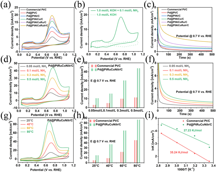
The AOR performance of the Pd@PtNiCoRuIr/C catalyst were firstly evaluated by cyclic voltammetry (CV) measurements in 1.0 mol/L KOH + 0.1 mol/L NH3·H2O electrolyte using commercial Pt/C and a series of gradient metal-modified Pd@Pt-based catalysts (Pd@Pt/C, Pd@PtNi/C, Pd@PtNiCo/C, and Pd@PtNiCoRu/C) as benchmarking references (Fig. S14 in Supporting information). In preliminary experiments, the reaction conditions were optimized by systematically varying the concentration of Pluronic F127, with the optimal concentration identified (Fig. S15 in Supporting information). The CV curves presented in the presence and absence of NH3 (Fig. 2a) revealed distinct peaks for ammonia oxidation within the potential range of 0.40–0.90 V versus RHE. Fig. 2b shown that Pd@PtNiCoRuIr/C catalyst exhibited a significantly enhanced oxidation current density at 0.7 V (vs. RHE), achieving 3.83-, 2.21-, 1.65-, 1.24-, and 1.11-fold improvements compared to commercial Pt/C, Pd@Pt/C, Pd@PtNi/C, Pd@PtNiCo/C, and Pd@PtNiCoRu/C, respectively. Concurrently, the onset oxidation potential of Pd@PtNiCoRuIr/C negatively shifted to 0.44 V, corresponding to a 0.11 V reduction relative to commercial Pt/C, underscoring the superior AOR kinetics. Notably, the apparent catalytic performance of the Pd@PtNiCoRuIr/C surpassed that of most previously reported catalysts (Table S2 in Supporting information). To investigate the electrochemical active surface area (ECSA) of the catalysts, CO stripping was measured in 0.1 mol/L KOH aqueous solution at a scan rate of 5 mV/s. As shown in Fig. S16 (Supporting information), Pd@PtNiCoRuIr/C catalyst was determined the highest ECSA (124.58 m2/g) among all investigated control samples, which was approximately 2.18, 1.08, 1.42, 1.01, and 1.03 times higher than those of commercial Pt/C, Pd@Pt/C, Pd@PtNi/C, Pd@PtNiCo/C, and Pd@PtNiCoRu/C, respectively, verifying that the lattice distortion in the structure indeed have induced more active sites exposure. Moreover, the Pd@PtNiCoRuIr/C catalyst still exhibited a superior AOR performance with higher current density when normalized to the ECSA, suggesting that the higher intrinsic electrocatalytic activity of Pd@PtNiCoRuIr/C than that of other control samples (Fig. S17 in Supporting information). Correspondingly, the fast AOR kinetic of Pd@PtNiCoRuIr/C was also confirmed by the lowest Tafel slope and the lowest charge transfer resistance (Figs. S18 and S19 in Supporting information). Alongside exceptional catalytic activity, extended stability represents another defining feature of high-performance electrocatalysts. The long-term stability was examined through the chronoamperometric (CA) method in a solution of 1 mol/L KOH and 0.1 mol/L NH3 at a potential of 0.7 V vs. RHE. Initially, all the electrocatalysts experienced a rapid decrease in current, which was attributed to the loss of nonbinary double-layer current and deactivation caused by Nads poisoning, after which the reaction reached a stable state [46]. The gradual reduction observed after stabilization is attributed to the continuous depletion of ammonia in the electrolyte. As ammonia undergoes irreversible conversion to N2, the efficiency of ammonia oxidation decreases over time, resulting in a decrease in current density (Fig. 2c). Nevertheless, the Pd@PtNiCoRuIr/C catalyst maintained the highest current density at the conclusion of the stability experiment, confirming its effective anti-poisoning capability. In addition, an accelerated degradation study of the Pd@PtNiCoRuIr/C catalyst was also conducted via 1000 continuous CV cycles, and the curve showed that Pd@PtNiCoRuIr/C retained 81.4% of its initial peak current density, significantly surpassing the 44.5% retention observed for commercial Pt/C, revealing the good durability of the Pd@PtNiCoRuIr/C NPs (Fig. S20 in Supporting information). TEM and EDS line-scan analyses were subsequently performed to investigate the structural integrity after the durability test. The "post-AOR" TEM and EDS line-scan results revealed that the Pd@PtNiCoRuIr/C showed no evident collapse of the core-shell mesoporous architecture or metal particle agglomeration after long-term AOR tests, indicating strong chemical structural stability (Fig. S21 in Supporting information). The above findings collectively highlight the synergistic role of multicomponent alloying strategies and core-shell mesoporous design in not only enhancing catalytic activity but also mitigating active-site poisoning and structural degradation. Beyond the intrinsic activity of catalysts, the regulatory effects of key parameters (NH3 concentration, operating temperature, and KOH concentration) on AOR kinetics were also systematically investigated. Within the NH3 concentration range of 0.05–0.5 mol/L, the mass activity of Pd@PtNiCoRuIr/C at 0.7 V (vs. RHE) increased from 10.53 mA/cm2 to 44.22 mA/cm2, while commercial Pt/C exhibited a smaller enhancement, indicating the higher NH3 catalytic capacity (Figs. 2d and e, Fig. S22 in Supporting information). CA tests further confirmed the positive correlation between NH3 concentration and AOR activity (Fig. 2f). More importantly, Pd@PtNiCoRuIr/C demonstrated superior performance, achieving a 3.1-fold higher peak current density and an 80 mV negative shift in onset potential compared to commercial Pt/C under Zn-NH3 battery operational conditions (1 mol/L KOH + 0.3 mol/L NH3), highlighting the potential practical application capability (Fig. S23 in Supporting information). The temperature-dependent studies showed that increasing the operating temperature from 25 ℃ to 80 ℃ enhanced the peak current density of Pd@PtNiCoRuIr/C by 5.73-fold, accompanied by a 74 mV negative shift in onset potential, indicative of the enhanced reaction kinetics of NH3 oxidation and reduced activation energy (Figs. 2g and h). Moreover, the analysis of Arrhenius plots (ln(J) vs. 1000/T, Fig. 2i) derived from data in Fig. 2g and Fig. S24 (Supporting information) revealed linear relationships, confirming unchanged reaction mechanisms during thermal activation. The calculated standard electrochemical activation enthalpies at 0.7 V were 27.23 kJ/mol for Pd@PtNiCoRuIr/C, which was lower than commercial Pt/C (35.24 kJ/mol), underscoring the enhanced intrinsic activity, faster charge transfer kinetics, and reduced energy consumption during AOR (Fig. 2i). Additionally, alkaline environment modulation experiments demonstrated that increasing KOH concentration from 0.5 mol/L to 5.0 mol/L improved peak current densities for both catalysts (Fig. S25 in Supporting information). Notably, Pd@PtNiCoRuIr/C exhibited a 1.8-fold current density increase and a 130 mV negative shift in onset potential, attributed to the OH--facilitated NH3 deprotonation and intermediate desorption. The above multiparameter optimization studies elucidate kinetic bottlenecks in AOR pathways and provide theoretical guidance for operational parameter matching in practical Zn-NH3 battery systems.
Figure 2
Figure 2.
(a) CV curves of Pd@PtNiCoRuIr/C and the references in Ar-saturated 1.0 mol/L KOH with 0.1 mol/L NH3. (b) CV curves of Pd@PtNiCoRuIr/C in the presence and absence of NH3. (c) CA curves of Pd@PtNiCoRuIr/C and the references in Ar-saturated 1.0 mol/L KOH with 0.1 mol/L NH3 at 0.7 V vs. RHE. (d) CV curves of Pd@PtNiCoRuIr/C in Ar-saturated 1.0 mol/L KOH electrolytes with different NH3 concentrations at room temperature. (g) CV curves of Pd@PtNiCoRuIr/C measured in Ar-saturated 1.0 mol/L KOH with 0.1 mol/L NH3 recorded at different temperatures. (e, h) AOR activity comparison for Pd@PtNiCoRuIr/C and commercial Pt/C in the presence of different NH3 concentrations or different temperatures at 0.7 V vs. RHE. (f) CA of Pd@PtNiCoRuIr/C in Ar-saturated 1.0 mol/L KOH with different NH3 concentrations under ambient conditions at 0.7 V vs. RHE. (i) Arrhenius plots for NH3 oxidation on Pd@PtNiCoRuIr/C and commercial Pt/C catalysts at 0.7 V vs. RHE.
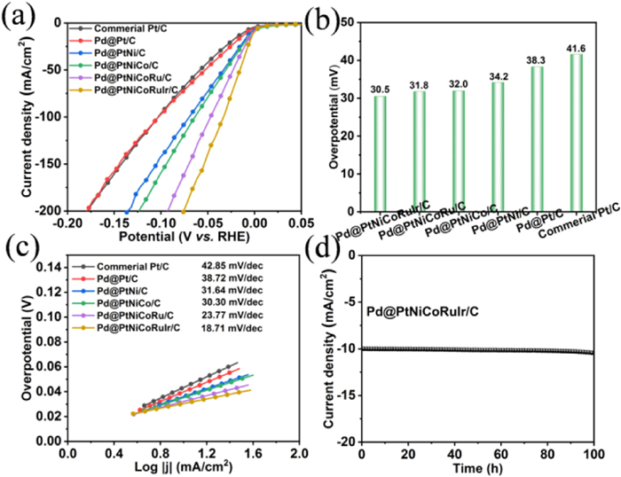
To investigate the bifunctional performance of the catalyst, HER testing was further conducted in the same electrolyte containing 1 mol/L KOH and 0.3 mol/L NH3·H2O. As shown in Figs. 3a and b, Pd@PtNiCoRuIr/C exhibited the lowest overpotential of 30.5 mV at a current density of 10 mA/cm2, superior to commercial Pt/C (41.6 mV), Pd@Pt/C (38.3 mV), Pd@PtNi/C (34.2 mV), Pd@PtNiCo/C (32.0 mV), Pd@PtNiCoRu/C (31.8 mV) and the most of the previously reported catalysts (Table S3 in Supporting information). The Tafel slopes derived from linear sweep voltammetry (LSV) were calculated to explore the kinetics (Fig. 3c). The Tafel slopes were determined to be 42.8 mV/dec for commercial Pt/C, 38.7 mV/dec for Pd@Pt/C, 31.6 mV/dec for Pd@PtNi/C, 30.3 mV/dec for Pd@PtNiCo/C, 23.7 mV/dec for Pd@PtNiCoRu/C, and 18.7 mV/dec for Pd@PtNiCoRuIr/C, highlighting the progressive enhancement in HER activity with the sequential incorporation of metal components in the catalyst architecture. In addition, the chronoamperometric curve in Fig. 3d revealed that the Pd@PtNiCoRuIr/C catalyst exhibited negligible variation in current density over 100 h at an overpotential of 30.5 mV, demonstrating exceptional long-term stability originating from the PtNiCoRuIr high-entropy alloy shell protection effect [47]. Benefiting from the mesoporous core-shell structure, multi-metallic synergy and lattice distortion effect, the Pd@PtNiCoRuIr/C catalyst achieves significantly enhanced bifunctional activity and stability for both AOR and HER.
Figure 3
Figure 3.
HER performance in Ar-saturated 1.0 mol/L KOH and 0.3 mol/L NH3·H2O. (a) LSV curves of Pd@PtNiCoRuIr/C and reference samples. (b) Overpotential comparison of Pd@PtNiCoRuIr/C and reference samples at a current density of 10 mA/cm2. (c) Tafel plots of Pd@PtNiCoRuIr/C and reference samples. (d) CA curve of Pd@PtNiCoRuIr/C at 10 mA/cm2.
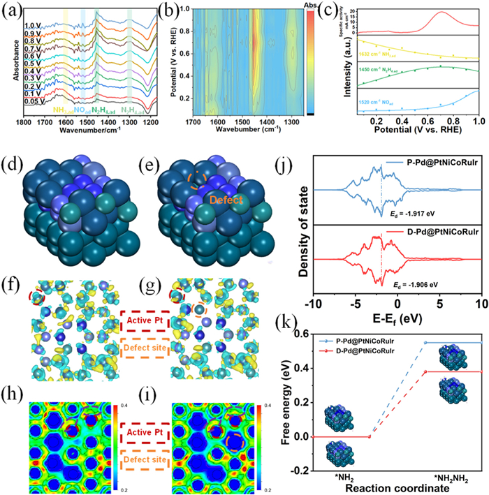
In situ FTIR measurements were conducted to systematically elucidate the dynamic mechanism of the AOR on a Pd@PtNiCoRuIr/C electrode (0.05–1.0 V vs. RHE). In situ infrared spectroscopy revealed distinct vibrational peaks at 1450, 1520, and 1632 cm-1, attributed to adsorbed hydrazine (N2H4,ad), adsorbed nitric oxide (NOad), and adsorbed ammonia (NH3,ad), respectively (Fig. 4a) [48]. The unambiguous detection of N2H4,ad directly validates the core hypothesis of the Gerischer-Mauerer (G-M) pathway-where NH3 undergoes dehydrogenation to form NH2,ad intermediates, which subsequently couple to generate N2H4,ad as a key intermediate before final conversion to N2. Notably, NH3,ad consumption (evidenced by the attenuation of the 1632 cm-1 peak) correlates strongly with enhanced reaction activity at elevated potentials (Figs. 4b and c) [49]. Meanwhile, the concentration of N2H4,ad (1450 cm-1 peak) exhibits a non-monotonic trend, first increasing and then decreasing: In the low-potential region (< 0.7 V), the coupling of two NH2,ad species dominates, leading to the accumulation of N2H4,ad. At higher potentials (> 0.7 V), rapid decomposition of N2H4,ad (e.g., via N2 desorption) or the further oxidation (potentially generating NOad) becomes predominant, causing the decline. Importantly, the NO peak intensity for the Pd@PtNiCoRuIr/C catalyst is relatively weak at high potentials, indicating that fewer byproducts are present during the AOR process and that it may have a higher FE. This behavior highlights the critical role of the HEA shell in suppressing side reactions: lattice distortion-induced strain fields and multi-metallic synergy weaken the adsorption strength of oxygen-containing intermediates (e.g., NOad), thereby enhancing selectivity toward N2 production. The in situ FTIR results confirmed that ammonia oxidation proceeds through successive dehydrogenation steps, forming N2H4 species in accordance with the intermediates proposed in the G-M mechanism: the reaction initiates on the catalyst surface through coadsorption of NH3 and OH-, resulting in the gradual dehydrogenation of NH3 into various adsorbed intermediates (NHad, NH2,ad) that subsequently recombine to form N2Hy, ad (y = 2–4) species, which ultimately dehydrogenate to produce N2 as the final product [50]. To investigate the defect-rich characteristics of Pd@PtNiCoRuIr, comparative models of pristine P-Pd@PtNiCoRuIr and defect-engineered D-Pd@PtNiCoRuIr were constructed (Figs. 4d and e). Charge density difference analysis (Figs. 4f and g) and electrostatic potential mapping (Figs. 4h and i) were firstly conducted and jointly revealed significant electron transfer from adjacent atoms (e.g., Ni/Co) to Pt sites in the defect-rich D-Pd@PtNiCoRuIr, consistent with XPS observations of Pt valence state downshifting. In addition, the d-band center was further performed to elucidate the electronic regulation variation. As illustrated, the d-band center of Pt in D-Pd@PtNiCoRuIr shifted closer to the Fermi level compared to the pristine counterpart, enhancing the hybridization between Pt d-orbitals and reaction intermediates (Fig. 4j). Notably, based on the derived G-M pathway for AOR, where the rate-determining step (RDS) is identified as NH2,ad → N2H4,ad, the energy barrier of the speed determining step was also calculated. Gibbs free energy calculations demonstrated that the RDS on D-Pd@PtNiCoRuIr exhibits a lower energy barrier and superior adsorption stability of N2H4,ad intermediates (Fig. 4k) [51,52]. This electronic optimization, driven by defect-induced charge redistribution and d-band center modulation, significantly accelerates the AOR kinetics, aligning with experimental enhancements in catalytic activity.
Figure 4
Figure 4.
(a) In situ FTIR spectra of the Pd@PtNiCoRuIr/C in 1 mol/L KOH and 0.1 mol/L NH3 for AOR. (b) Contour plot of in situ FTIR spectra for Pd@PtNiCoRuIr/C. (c) Potential dependence of the current and the normalized band area of NH3,ad, N2H4,ad, and NOad for Pd@PtNiCoRuIr/C electrodes. (d, e) Model diagrams of P-Pd@PtNiCoRuIr and D-Pd@PtNiCoRuIr. (f, g) Differential charge density for P-Pd@PtNiCoRuIr and D-Pd@PtNiCoRuIr. Electrostatic Potential Maps of (h) P-Pd@PtNiCoRuIr and (i) D-Pd@PtNiCoRuIr. (j) DOS of P-Pd@PtNiCoRuIr and D-Pd@PtNiCoRuIr. (k) Gibbs free energy diagrams for the rate-determining steps in the AOR on P-Pd@PtNiCoRuIr and D-Pd@PtNiCoRuIr.
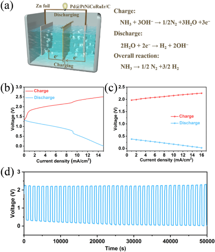
On the basis of the superior electrocatalytic HER/AOR activity of Pd@PtNiCoRuIr/C catalyst, a novel rechargeable Zn-NH3 battery was constructed (Fig. 5a). The battery employs carbon paper loaded with the Pd@PtNiCoRuIr/C catalyst as the cathode, zinc foil as the anode, and an anion-exchange membrane (AEM) as the separator, with an anolyte of 1 mol/L KOH + 0.02 mol/L Zn(CH3COO)2 and a catholyte of 1 mol/L KOH + 0.3 mol/L NH3·H2O. During discharge, zinc was oxidized at the anode (Zn + 4OH- → Zn(OH)42- + 2e-) releases electrons to drive hydrogen evolution at the cathode (2H2O + 2e- → H2 + 2OH-), converting zinc's chemical energy into hydrogen and electrical energy. During charging, NH3 oxidation via AOR generates N2 (NH3 + 3OH- → ½N2 + 3H2O + 3e-) at the cathode, while Zn2+ reduction (Zn(OH)42- + 2e- → Zn + 4OH-) regenerates metallic zinc at the anode, storing external energy as chemical potentials of Zn and N2. The assembled Zn-NH3 cell revealed a stable open-circuit voltage of 1.315 V (maintained for 2 h), the feasibility of the Zn-NH3 battery (Fig. S26 in Supporting information). The charge-discharge polarization profile derived from the LVS curves from the discharge and charge process are successfully obtained, further proving the practicability of the Zn-NH3 battery (Fig. 5b and Fig. S27 in Supporting information). At current densities of 1–16 mA/cm2, the discharge voltage decreased from 0.38 V to 0.03 V, while the charge voltage increased from 1.97 V to 2.25 V, demonstrating the superior rate capability (Fig. 5c and Fig. S28 in Supporting information). In addition to battery performance, long-term durability is also critical. Long-term cycling tests showed minimal voltage fluctuation over 50,000 s at 16 mA/cm2, highlighting exceptional stability (Fig. 5d). Furthermore, we also conducted a stability test that lasted for 100 h, which further demonstrated its excellent stability (Fig. S29 in Supporting information). To confirm the electrochemical reactions, gas products during cathodic charge/discharge processes were analyzed via gas chromatography. As shown in Fig. S30 (Supporting information), a significant amount of H2 was detected after 500 s of discharging at 16 mA/cm2, while the concentrations of N2 and O2 remained constant, indicating the occurrence of the HER with a FE reaching approximately 92.3% (Fig. S31 in Supporting information). During the charging process at 16 mA/cm2 for 500 s, the N2 content increased substantially whereas the O2 level remained unchanged, demonstrating ammonia oxidation to nitrogen. Furthermore, compared with other battery systems, this material demonstrates significant advantages in key performance parameters such as energy density, cycle stability, and FE (Table S4 in Supporting information). Experimental results indicate that the Pd@PtNiCoRuIr/C catalyst achieves high FE and exhibits exceptional durability by optimizing charge/discharge kinetics, providing critical theoretical foundations and technical feasibility for its application in hydrogen energy storage and conversion. Despite the progress made in the design and development of high-entropy alloy materials electrocatalysts for AOR/HER, there are still several issues that need to do be done in the future: (1) Long-term stability testing under industrial conditions are need to be further conducted (e.g., 1000+ h at elevated temperatures or industrial current densities); (2) Developing HEA variants with earth-abundant metals (e.g., Fe, Mn) to reduce costs while maintaining performance; (3) Prototyping scalable Zn-NH3 battery stacks and integrating them with ammonia synthesis/transport infrastructure.
Figure 5
Figure 5.
Electrochemical performance of the Zn−NH3 battery. (a) Schematic illustration of the Zn−NH3 battery. (b) Charge and discharge polarization curves. (c) Discharge and charge voltage profiles. (d) Galvanostatic discharge−charge cycling curves at 16 mA/cm2.
In conclusion, Pd@PtNiCoRuIr core-shell mesoporous bifunctional electrocatalysts with rich lattice distortion was demonstrated employing a triblock copolymer-mediated wet-chemical synthesis strategy. Through multiscale coordination between the core and shell layers, coupled with lattice distortion and mesoporous-confinement-enabled interfacial coupling effects, the optimized material demonstrated exceptional alkaline HER and AOR performance. Benefiting from the bifunctional characteristics, a rechargeable Zn-NH3 battery system was assembled and achieved a 92.3% Faradaic efficiency for NH3-to-H2 conversion with remarkable cycling stability at 16 mA/cm2. Our work can offer a novel direction for the construction of HEA materials for efficient and continuous NH3-to-H2 transformation.
Declaration of competing interest
The authors declare that they have no known competing financial interests or personal relationships that could have appeared to influence the work reported in this paper.
This study is provided by the National Natural Science Foundation of China (No. 52573275), Taishan Scholars Program of Shandong Province (No. tsqn202507205), Youth Innovation Team of Higher Education Institutions in Shandong Province (No. 2023KJ105), and Collaborative Innovation Center of Yellow River Basin Pharmaceutical Green Manufacturing and Engineering Equipment, University of Jinan, Jinan 250022, China, Jinan City University Integration Development Strategy Project (No. JNSX2023021). This work was also supported by Talents' plan Foundation of Guangdong Second Provincial General Hospital (No. 2024D003) and Science and Technology Projects in Guangzhou (No. 2025A04J4629).
Supplementary materials
Supplementary material associated with this article can be found, in the online version, at doi:10.1016/j.cclet.2025.111826.
[1]
F. Chang, W. Gao, J. Guo, et al., Adv. Mater. 33 (2021) 2005721. doi: 10.1002/adma.202005721
[2]
X. Gao, Y. Zhang, S. Yin, et al., Adv. Funct. Mater. 32 (2022) 2204833. doi: 10.1002/adfm.202204833
[3]
Y. Sun, K. Xu, Z. Wei, et al., Adv. Mater. 30 (2018) 1802121. doi: 10.1002/adma.201802121
[4]
D. Khan, W.J. Ong, Interdiscip. Mater. 4 (2025) 249–283.
[5]
H. Pan, J. Li, Y. Wang, et al., Adv. Sci. 11 (2024) 2402651. doi: 10.1002/advs.202402651
Figure 1
Morphology and structural characterization of Pd@PtNiCoRuIr. (a) Schematic illustration of the synthesis of Pd@PtNiCoRuIr. (b) Low-magnification and (c) high-magnification TEM images. (d, e) AC—HAADF-STEM images. (f, g) corresponding IFFT patterns labeled within red dashed boxes in the AC—HAADF-STEM images. (h) EDX line-scan spectrum. (i) HAADF-STEM image and corresponding EDX elemental mapping images.
Figure 2
(a) CV curves of Pd@PtNiCoRuIr/C and the references in Ar-saturated 1.0 mol/L KOH with 0.1 mol/L NH3. (b) CV curves of Pd@PtNiCoRuIr/C in the presence and absence of NH3. (c) CA curves of Pd@PtNiCoRuIr/C and the references in Ar-saturated 1.0 mol/L KOH with 0.1 mol/L NH3 at 0.7 V vs. RHE. (d) CV curves of Pd@PtNiCoRuIr/C in Ar-saturated 1.0 mol/L KOH electrolytes with different NH3 concentrations at room temperature. (g) CV curves of Pd@PtNiCoRuIr/C measured in Ar-saturated 1.0 mol/L KOH with 0.1 mol/L NH3 recorded at different temperatures. (e, h) AOR activity comparison for Pd@PtNiCoRuIr/C and commercial Pt/C in the presence of different NH3 concentrations or different temperatures at 0.7 V vs. RHE. (f) CA of Pd@PtNiCoRuIr/C in Ar-saturated 1.0 mol/L KOH with different NH3 concentrations under ambient conditions at 0.7 V vs. RHE. (i) Arrhenius plots for NH3 oxidation on Pd@PtNiCoRuIr/C and commercial Pt/C catalysts at 0.7 V vs. RHE.
Figure 3
HER performance in Ar-saturated 1.0 mol/L KOH and 0.3 mol/L NH3·H2O. (a) LSV curves of Pd@PtNiCoRuIr/C and reference samples. (b) Overpotential comparison of Pd@PtNiCoRuIr/C and reference samples at a current density of 10 mA/cm2. (c) Tafel plots of Pd@PtNiCoRuIr/C and reference samples. (d) CA curve of Pd@PtNiCoRuIr/C at 10 mA/cm2.
Figure 4
(a) In situ FTIR spectra of the Pd@PtNiCoRuIr/C in 1 mol/L KOH and 0.1 mol/L NH3 for AOR. (b) Contour plot of in situ FTIR spectra for Pd@PtNiCoRuIr/C. (c) Potential dependence of the current and the normalized band area of NH3,ad, N2H4,ad, and NOad for Pd@PtNiCoRuIr/C electrodes. (d, e) Model diagrams of P-Pd@PtNiCoRuIr and D-Pd@PtNiCoRuIr. (f, g) Differential charge density for P-Pd@PtNiCoRuIr and D-Pd@PtNiCoRuIr. Electrostatic Potential Maps of (h) P-Pd@PtNiCoRuIr and (i) D-Pd@PtNiCoRuIr. (j) DOS of P-Pd@PtNiCoRuIr and D-Pd@PtNiCoRuIr. (k) Gibbs free energy diagrams for the rate-determining steps in the AOR on P-Pd@PtNiCoRuIr and D-Pd@PtNiCoRuIr.
Figure 5
Electrochemical performance of the Zn−NH3 battery. (a) Schematic illustration of the Zn−NH3 battery. (b) Charge and discharge polarization curves. (c) Discharge and charge voltage profiles. (d) Galvanostatic discharge−charge cycling curves at 16 mA/cm2.


 DownLoad:

 下载:
下载:


 下载:
下载:
