High-performance bifunctional electrocatalyst (NiFe-LDH/MoNi4) with enhanced chloride corrosion resistance for achieving seawater overall-splitting at industrial temperature
Citation:
Gang Zhao, Wenbo Liao, Lan Mu, Baojie Zhang, Ning Zhao, Tianyong Zhang, Xijin Xu. High-performance bifunctional electrocatalyst (NiFe-LDH/MoNi4) with enhanced chloride corrosion resistance for achieving seawater overall-splitting at industrial temperature[J]. Chinese Chemical Letters,
2026, 37(5): 111825.
doi:
10.1016/j.cclet.2025.111825
High-performance bifunctional electrocatalyst (NiFe-LDH/MoNi4) with enhanced chloride corrosion resistance for achieving seawater overall-splitting at industrial temperature
English
High-performance bifunctional electrocatalyst (NiFe-LDH/MoNi4) with enhanced chloride corrosion resistance for achieving seawater overall-splitting at industrial temperature
sps_xuxj@ujn.edu.cn (X. Xu). 1 These authors contributed equally to this work.
Received Date:
20 December 2024 Accepted Date:
10 September 2025 Revised Date:
10 September 2025 Available Online:
15 May 2026
Abstract:
Nickel-iron double hydroxides are corroded by Cl− during seawater electrolysis, which reduces their catalytic activity and stability. Here, a high-performance bifunctional electrocatalyst (NiFe-LDH/MoNi4) with enhanced chloride corrosion resistance was synthesized. In the OER process, Mo element in the catalyst was reconstructed to form MoO42−, which repelled Cl− to prevent the catalyst from being corroded. Besides, the heterostructure of NiFe-LDH/MoNi4 decreased the reduction of HER active site during HER process (Mo element dissolves easily in alkaline media due to thermodynamic instability). Therefore, based on in-situ self-reconstruction of Mo element and heterostructure in alkaline seawater, NiFe-LDH/MoNi4 delivered a current density of 10 mA/cm2 for the HER (OER) at industrial temperatures (80 ℃) with an overpotential of merely 32 mV (139 mV). Additionally, when NiFe-LDH/MoNi4 is employed as both the anode and cathode, a battery voltage of just 1.39 V (3.13 V) is sufficient to attain a current density of 10 mA/cm2 (1 A/cm2). The system is also capable of sustained operation at a high current density of 500 mA/cm2 for a period of 50 h.
Currently, integrating "green energy" with the process of electrocatalytic seawater splitting represents a sustainable and economical approach to hydrogen production [1–4]. This method entails the hydrogen evolution reaction (HER) occurring at the cathode and the oxygen evolution reaction (OER) taking place at the anode [5–9]. However, the presence of chloride ions (Cl−) in seawater interferes with the OER, resulting in catalyst corrosion and a decline in both catalytic activity and stability [10–12]. Additionally, the OER is characterized by a complicated four-electron transfer mechanism that generally demands a high overpotential for proper function. Consequently, minimizing the overpotential associated with the OER is a crucial objective for enhancing the efficiency of water splitting [13–17]. This underscores the necessity for the development of electrocatalysts that are not only high-performing but also resistant to corrosion for effective seawater electrolysis.
In recent years, nickel iron layered double hydroxide (NiFe-LDH) has attracted considerable interest as an effective electrocatalyst for the OER. This interest is largely due to its cost-effectiveness, straightforward synthesis, and exceptional catalytic performance in alkaline environments [18–22]. However, its limited active sites and poor electrical conductivity limit the overall water splitting performance [23]. Furthermore, during the seawater oxidation process, NiFe-LDH are prone to be corroded by Cl− in seawater, which subsequently reduces their catalytic activity and stability [24]. To address this, methods such as constructing heterojunctions, elemental protection, and interface engineering can be employed to enhance resistance to Cl− corrosion and improve OER performance. For example, the built-in electric field formed between heterogeneous interfaces can facilitate electron transport and adjust the electronic structure. Zhang et al. deposited a nickel metal layer on NiFe-LDH, causing the electron transfer from the Ni layer to the NiFe-LDH layer. During the OER process, the change in local electronic density at the heterojunction interface leads to a decrease in the overpotential of NiFe-LDH at a current density of 10 mA/cm2, reducing it from 285 mV to 235 mV [25]. The issue of chlorine corrosion in seawater electrolysis can be overcome by constructing a chlorine-blocking layer. Wang et al. coated MnOx onto NiFe-LDH via electro-deposition, where the MnOx layer repelled Cl−, but not as an active site for OER or HER [26]. Having a bifunctional electrocatalyst that can perform both OER and HER helps streamline the overall system design and save expenses. Currently, most research is dedicated to enhancing OER performance and resistance to Cl− corrosion, with little focus on combining improvements in the HER performance of catalysts with enhancements in OER performance and resistance to Cl− corrosion, to develop dual-functional catalysts that are corrosion-resistant in alkaline seawater.
Based on previous research, our objectives were to enhance the corrosion resistance and seawater overall-splitting capability of catalysts. Here, we find a Cl− resistant layer that serves as an HER active site, thereby constructing a high-performance bifunctional electrocatalyst (NiFe-LDH/MoNi4) with enhanced chloride corrosion resistance for achieving seawater overall-splitting at industrial temperature. As an OER catalyst, the nickel molybdenum alloy protected the nickel substrate from corrosion, and molybdenum was oxidized and dissolved under high oxidative potentials to form MoO42−. The formation of MoO42− acts as a barrier layer against chloride ions, thereby improving the corrosion resistance during the OER [27]. As a catalyst for the HER, the NiFe-LDH/MoNi4 heterostructure helps mitigate the decline of active HER sites, thereby enhancing stability. In situ reconstruction process involving the Mo element has resulted in the development of an anti-Cl⁻ protective layer, alongside an internal electric field established by the heterojunction. This modification has optimized the position of the d-band center within the catalyst, thereby optimizing the adsorption of intermediate products throughout the catalytic cycle. In alkaline seawater (1 mol/L KOH + seawater), the NiFe-LDH/MoNi4 exhibited the ability to generate a current density of 10 mA/cm2 for the HER at industrial temperatures of 80 ℃, accompanied by an overpotential of 32 mV, while for the OER, the overpotential was 139 mV. Additionally, when employed as both the anode and cathode, the NiFe-LDH/MoNi4 system necessitated a battery voltage of only 1.39 V to achieve a current density of 10 mA/cm2 and 3.13 V to reach 1 A/cm2. Significantly, this system is capable of maintaining continuous operation at a current density of 500 mA/cm2 for a duration of up to 50 h.
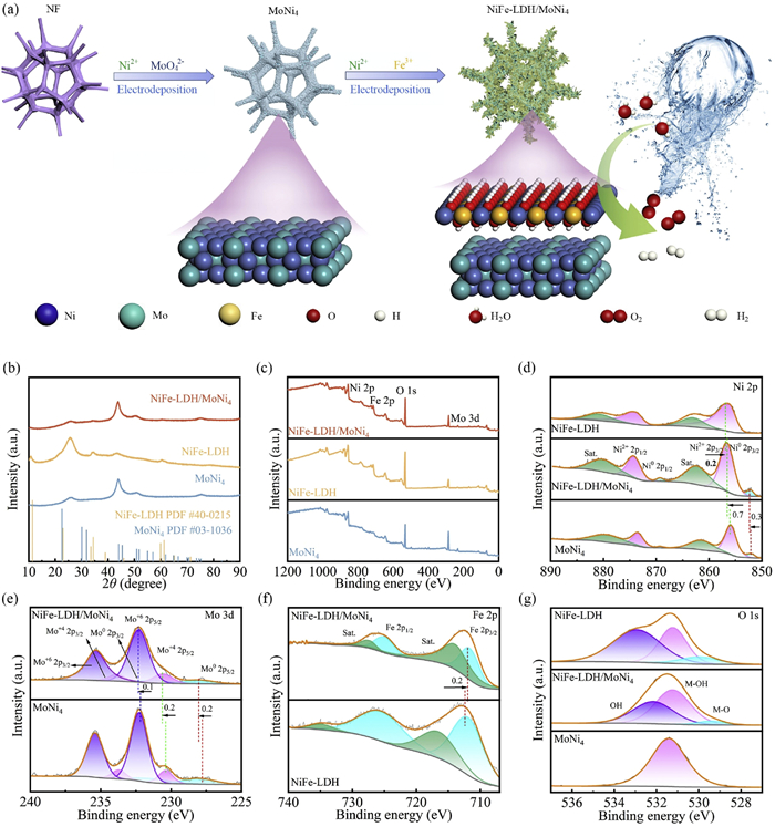
Fig. 1a provides a depiction of the synthesis procedure for NiFe-LDH/MoNi4. Firstly, a layer of MoNi4 alloy is deposited on nickel foam via electro-deposition, which protects the nickel substrate from corrosion and improves catalytic stability. Subsequently, lamellar NiFe-LDH is electro-deposited onto the MoNi4 layer to construct the NiFe-LDH/MoNi4 structure. The XRD patterns (Fig. 1b and Fig. S1 in Supporting information) reveal the peaks associated with NiFe-LDH/MoNi4 and MoNi4 materials at angles of 50.8°, 64.7°, and 75°, which correspond to the (310), (400), and (312) crystal planes of MoNi4 (PDF #03–1036). Additionally, peaks observed at 10.88°, 34.37°, and 59.96° can be attributed to the (003), (012), and (110) planes of NiFe-LDH (PDF #40–0215).
Figure 1
Figure 1.
(a) Synthesis procedure for NiFe-LDH/MoNi4. (b) XRD patterns and (c) XPS survey spectra for NiFe-LDH/MoNi4, NiFe-LDH, and MoNi4. (d) Ni 2p for NiFe-LDH/MoNi4, NiFe-LDH, and MoNi4. (e) Mo 3d for NiFe-LDH/MoNi4 and MoNi4. (f) Fe 2p for NiFe-LDH/MoNi4 and NiFe-LDH. (g) O 1s for NiFe-LDH/MoNi4, NiFe-LDH, and MoNi4.
XPS analyses of NiFe-LDH/MoNi4 (Fig. 1c) demonstrate the existence of Ni, Fe, O, and Mo. These findings agree with the findings obtained from the energy-dispersive spectrum (Fig. S2 in Supporting information). In Fig. 1d, the peaks at 852 and 852.3 eV represent Ni0 2p3/2 for both MoNi4 and NiFe-LDH/MoNi4. Similarly, the peaks at 869.2 and 869.4 eV are assigned to Ni0 2p1/2 for the same materials. Additionally, peaks at 856, 856.6, and 856.78 eV correspond to Ni2+ 2p3/2 in MoNi4, NiFe-LDH/MoNi4, and NiFe-LDH, respectively. The Ni2+ 2p1/2 states are represented by peaks at 873.6, 873.4, and 874.28 eV for MoNi4, NiFe-LDH/MoNi4, and NiFe-LDH, respectively. In Fig. 1e, the peaks at 227.7 and 227.9 eV correspond to Mo0 2p5/2 for both MoNi4 and NiFe-LDH/MoNi4, while the peaks at 231.3 and 231.5 eV correspond to Mo0 2p3/2 for the same materials. Fig. 1f shows peaks at 712.28 and 712 eV associated with Fe 2p3/2 for NiFe-LDH and NiFe-LDH/MoNi4, along with peaks at 726.48 and 725.3 eV for Fe 2p1/2 in the same compounds. Within the NiFe-LDH/MoNi4 compound, the binding energies of Ni0 2p3/2 and Mo0 2p5/2 shift to higher energy levels relative to those in MoNi4. In contrast, the analysis has revealed that the binding energies for the Ni2+ 2p3/2 and Fe 2p3/2 orbitals in the NiFe-LDH/MoNi4 composite are lower than those recorded for the NiFe-LDH alone. This overall reduction in energy levels signifies an electron transfer from MoNi4 to NiFe-LDH in the NiFe-LDH/MoNi4 configuration, resulting in the establishment of robust electronic interactions at the interface between these materials. Such interactions modify the charge distribution of the catalyst and generate an internal electric field that promotes electron transfer and boosts catalytic performance [28]. The three peaks found in the O 1s spectra (Fig. 1g) are attributed to physically adsorbed water molecules, chemically adsorbed M–OH bonds, and M–O bonds, respectively [33].
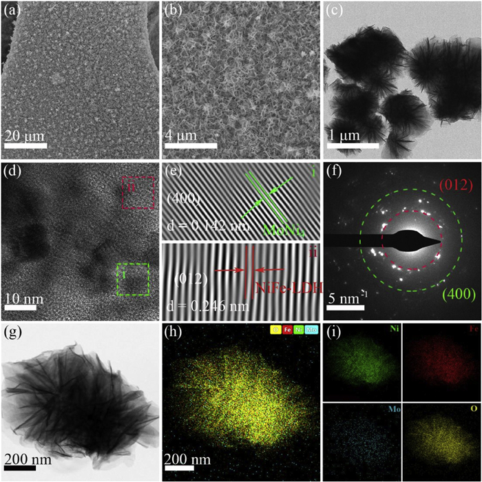
After the first electro-deposition, a layer of nickel molybdenum alloy particles (Fig. S3b in Supporting information) grows on the smooth foam nickel (Fig. S3a in Supporting information). Following the second electro-deposition, a layer of nanosheet is formed on the nickel molybdenum alloy (Figs. 2a and b). Compared with the deposition of NiFe-LDH on NF, the deposition of NiFe-LDH on MoNi4 reduces the aggregation of NiFe-LDH, thereby increasing the contact area between catalyst and electrolyte, which is conducive to catalytic reaction. TEM image in Fig. 2c shows the multilayered, wrinkled nanosheets. The two inserted boxes in Fig. 2d represent the polycrystalline texture of MoNi4 (green box ⅰ) and NiFe-LDH (red box ⅱ). The high-resolution transmission electron microscopy (HRTEM) imagery, focusing on particular regions depicted in Fig. 2d, exhibits lattice fringes with separations of 0.142 nanometers and 0.246 nanometers. These spacings correspond to the (400) crystallographic plane of MoNi4 and the (012) plane of NiFe-LDH, as confirmed by the data presented in Figs. 2e and f. Additionally, an elemental mapping analysis (Figs. 2g-i) of a micrometer-sized flake from the NiFe-LDH/MoNi4 composite showed a uniform distribution of the elements Ni, Mo, Fe, and O throughout the entire flake.
Figure 2
Figure 2.
(a, b) SEM images, (c, d) TEM images, (e) HRTEM images, and (f) the selected area electron diffraction (SAED) pattern of NiFe-LDH/MoNi4. (g-i) EDS elemental mappings.
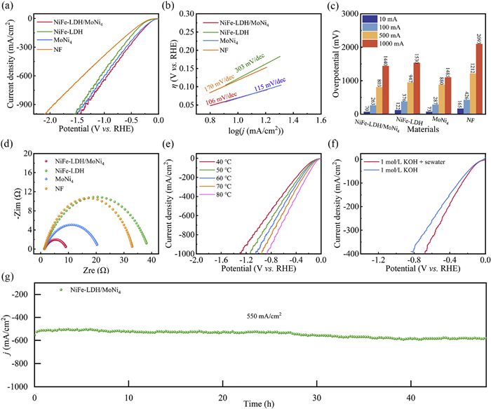
The performance of the catalysts in HER was evaluated in 1 mol/L KOH (Fig. S4 in Supporting information). The recorded overpotential for the HER of NiFe-LDH/MoNi4 is 77 mV at a current density of 10 mA/cm2. In order to alleviate freshwater constraints and make electrolyzed water more suitable for practical applications, we conducted HER tests on the catalysts in alkaline seawater (1 mol/L KOH + seawater). In Figs. 3a and c, the recorded overpotentials for the HER of NiFe-LDH/MoNi4 are 70 mV at a current density of 10 mA/cm2 and 263 mV at 100 mA/cm2. These values are lower than the overpotentials observed for MoNi4 (73 mV, 287 mV), NiFe-LDH (122 mV, 376 mV), and NF (165 mV, 426 mV). Furthermore, the Tafel slopes for different materials were obtained by fitting the LSV curves in order to analyze the reaction kinetics of the catalyst. According to the results presented in Fig. 3b, the Tafel slopes for NF, MoNi4, and NiFe-LDH were determined to be 303, 115, and 170 mV/dec, respectively. In contrast, the Tafel slope of NiFe-LDH/MoNi4 is only 106 mV/dec. It is clear that NiFe-LDH/MoNi4 exhibits more rapid kinetics during the HER.
Figure 3
Figure 3.
HER performance of electrocatalysts in alkaline seawater (1 mol/L KOH + seawater). (a) LSV, (b) Tafel, (c) different electrocatalyst HER overpotentials, (d) EIS plots, (e) LSV curves, (f) LSV curves of catalyst NiFe-LDH/MoNi4 under different environments, (g) stability tests (80 ℃).
The XPS analysis in Fig. 1 reveals that electrons transfer from the internal MoNi4 to the external NiFe-LDH. This transfer generates an internal electric field at the heterojunction, enhancing electron transport and altering the catalyst's electronic structure. To analyze the electron transfer resistance of the catalyst, the EIS method is employed. Based on the data shown in Fig. 3d, the radius of curvature of the other materials is greater than that of NiFe-LDH/MoNi4 (2.166 Ω, Table S1 in Supporting information). Furthermore, LSV is tested on the catalyst at various temperatures. In Fig. 3e, the HER performance of the catalyst improves correspondingly with increasing temperature. The overpotential of the catalyst HER reaches 32 mV at temperatures up to the industrial level of 80 ℃. The higher ionic concentration of the solution accounts for the catalyst's improved HER performance in alkaline seawater (Fig. 3f). Not only does a catalyst require good catalytic performance, but it also needs to demonstrate long-term stability. A 48-h stability test is performed on NiFe-LDH/MoNi4 at an ambient temperature of 80 ℃, with a high current density of 550 mA/cm2. In Fig. 3g, the curve remains largely stable, indicating good stability of the catalytic performance.
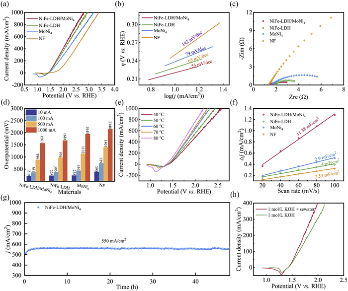
The performance of the catalysts in OER was evaluated in 1 mol/L KOH (Fig. S6 in Supporting information). The recorded overpotential for the OER of NiFe-LDH/MoNi4 is 223 mV at a current density of 10 mA/cm2. In order to alleviate freshwater constraints and make electrolyzed water more suitable for practical applications, we conducted OER tests on the catalysts in alkaline seawater. In Figs. 4a and d, the OER overpotential for NiFe-LDH/MoNi4 is measured at 219 mV at a current density of 10 mA/cm2, which is lower compared to the overpotentials of MoNi4 (238 mV), NiFe-LDH (228 mV), and NF (390 mV). The Tafel slope of each catalyst is determined through linear sweep voltammetry (LSV) analysis. As illustrated in Fig. 4b, the observed Tafel slopes for NiFe-LDH, MoNi4, and NF are 63, 79, and 142 mV/dec, respectively. Conversely, the Tafel slope measured for the NiFe-LDH/MoNi4 system amounts to a mere 53 mV/dec, suggesting that the kinetics of the OER reaction are more favorable for NiFe-LDH/MoNi4. The electron transfer resistance of catalyst is studied by EIS test. As seen in Fig. 4c, that the other materials have a greater radius of curvature compared to NiFe-LDH/MoNi4 (1.35 Ω, Table S1).
Figure 4
Figure 4.
OER performance of the catalysts in alkaline seawater (1 mol/L KOH + seawater). (a) LSV curves, (b) Tafel plots, (c) Nyquist plots, (d) comparison of overpotentials of different electrocatalysts, (e) LSV curves, (f) Cdl, (g) stability test (80 ℃), (h) OER performance of catalyst under different environments.
In addition, high temperature OER test was performed on the catalyst. LSV tests on the catalysts are conducted at different temperatures. The catalysts exhibit enhanced OER performance as the temperature increases, as seen in Fig. 4e, and when the temperature reaches the industrial temperature of 80 ℃, the OER overpotential of the catalyst is only 139 mV. By performing CV tests at different scan rates on the materials (Fig. S5 in Supporting information), the ECSA of the catalysts is calculated (Fig. 4f); the figure clearly demonstrates that the ECSA of NiFe-LDH/MoNi4 is much greater than that of the other catalysts, which is due to the fact that the growth of NiFe-LDH on MoNi4 reduces the agglomeration of NiFe-LDH and increases the contact area of the catalyst with the solution. Assessing the performance of a catalyst requires evaluating its stability. In order to evaluate the stability of NiFe-LDH/MoNi4, a 48-h trial is conducted at a current density of 550 mA/cm2 under a temperature of 80 ℃. Fig. 4g illustrates that the curve maintains a high level of stability, displaying little to no decrease in performance. The good stability of the catalyst in high temperature alkaline seawater electrolysis is due to the fact that, during the OER test, a small portion of the molybdenum in MoNi4 was oxidized and dissolved to form MoO42−, which repels Cl− and prevents the corrosion of NiFe-LDH and the substrate. In order to demonstrate the Cl− corrosion resistance of NiFe-LDH/MoNi4 during OER, we conducted stability tests on NiFe-LDH in alkaline seawater. The stability test curve for the OER of NiFe-LDH (Fig. S9a in Supporting information), reveals a marked decline in OER performance as the testing duration extends to 20 h. Comparison of the stability of NiFe-LDH and NiFe-LDH/MoNi4 in alkaline seawater shows that MoNi4 plays an anti-Cl− role in the OER process of NiFe-LDH/MoNi4. Fig. 4h indicates that the electrocatalyst demonstrates enhanced OER activity in alkaline seawater.
The performance of the catalysts in overall water splitting was evaluated in 1 mol/L KOH (Fig. S7 in Supporting information). As shown in Fig. S8a (Supporting information), an electrolytic cell is assembled with NiFe-LDH/MoNi4 as both cathode and anode. The recorded potential for the overall water splitting of NiFe-LDH/MoNi4 is 1.52 V at a current density of 10 mA/cm2. In order to alleviate freshwater constraints and make electrolyzed water more suitable for practical applications, we conducted overall water splitting tests on the catalysts in alkaline seawater. As depicted in Figs. S8b and c (Supporting information), NiFe-LDH/MoNi4 reaches current densities of 10 and 500 mA/cm2 at applied voltages of 1.51 and 2.93 V, respectively. In comparison, the voltages for NiFe-LDH, MoNi4, and NF correspond to 1.56 and 3.03 V, 1.53 and 3.2 V, and 1.78 and 3.60 V, respectively, indicating that the performance of NiFe-LDH/MoNi4 is notably superior. When tested at an industrial temperature of 80 ℃ in alkaline seawater, the electrocatalyst produces a current density of 10 mA/cm2 (1 A/cm2) with an observed voltage of only 1.39 V (3.13 V), as illustrated in Figs. S8d and e (Supporting information). The difference between the curves at 70 and 80 ℃ in Fig. S8d is not significant, which surfaces that the performance of the active sites of the catalysts has been optimized at the industrial temperature of 80 ℃. Additionally, Fig. S8f (Supporting information) highlights the remarkable overall performance of the electrocatalyst in facilitating water splitting within this environment. Stability tests are conducted in alkaline seawater at 80 ℃ under different current densities (100, 300, 500 mA/cm2), and Fig. S8g (Supporting information) shows that the curves remain largely stable, indicating good catalyst stability at low and high current densities.
Investigations are conducted on the catalyst's internal structure and the mechanism of the catalytic reaction to better comprehend the elements that enhance the catalyst's activity and stability. Fig. S11a (Supporting information) illustrates the atomic representation of the catalyst during the catalytic reaction. The position of the d-band center of the catalyst in relation to the Fermi level was established through an analysis of the valence band spectra obtained from XPS, as illustrated in Fig. S11b (Supporting information). According to the d-band center hypothesis, the interaction between the valence band of the adsorbed species and the d-band of a transition metal results in the formation of separate bonding and antibonding orbitals [34,35]. Bonding orbitals far below Ef are completely filled, while the filling of electrons in antibonding orbitals depends on the position of these energy states relative to Ef; the occupation of electrons in antibonding orbitals affects bond strength. The d-band center in NiFe-LDH/MoNi4 (3.83 eV) exhibits a downward shift in comparison to MoNi4 (3.36 eV). The XPS analysis presented in Fig. 1 indicates that following the electro-deposition of NiFe-LDH onto MoNi4, there is a transfer of electrons from MoNi4 to the NiFe-LDH. The catalyst's d-band center shifted away from Ef, resulting in a greater filling of antibonding orbitals. This ultimately decreases the binding affinity between the catalyst and hydrogen-containing species [29,30]. Which facilitates the desorption of hydrogen, thereby enhancing the HER activity. The d-band center of NiFe-LDH/MoNi4 is observed to move upward to 3.83 eV, in contrast to that of NiFe-LDH, which is at 4.58 eV. This upward movement of the d-band center makes it easier to minimize the amounts of electrons that fill antibonding orbitals, which ultimately results in an increase in the binding affinity between the catalyst and oxygenated intermediates [31,32].
We conducted absorption spectroscopy detection on the electrolyte before and after the OER stability test using an ultraviolet spectrometer to further explore the reasons for the Cl− corrosion resistance of NiFe-LDH/MoNi4. Fig. S11c (Supporting information) shows the ultraviolet absorption spectra of the solution, recorded both before and after the OER stability test. In Fig. S11c, compared to the solution before the OER test, there is an absorption peak at 352 nm wavelength in the solution after the test. This absorption peak originates from MoO42−, indicating that during the OER test, molybdenum atoms in MoNi4 are oxidized into MoO42− and dissolved. Fig. S11d (Supporting information) illustrates the corrosion behavior of the NF substrate of NiFe-LDH by Cl− during the OER test. The stability test curve for the OER of NiFe-LDH, displayed in Fig. S9a, reveals a marked decline in OER performance as the testing duration extends to 20 h, aligning with previous findings. In Fig. S11e (Supporting information), during the OER test, a small portion of molybdenum atoms in MoNi4 within NiFe-LDH/MoNi4 are oxidized into MoO42− (Fig. S11c). The MoO42− acts as a barrier layer effectively preventing the corrosion caused by Cl−, thereby ensuring good OER stability (Fig. 4g). Additionally, compared to MoNi4, the heterostructure of NiFe-LDH/MoNi4 mitigates the dissolution of Mo metal during the HER reaction, enhancing the HER stability (Fig. 3g). However, in Fig. S9b (Supporting information), the HER stability of MoNi4 is tested, and it is observed that the activity of the catalyst gradually decreases. As illustrated in Fig. S10 (Supporting information), the SEM images show that the structure of the catalyst NiFe-LDH/MoNi4 remains intact after the stability test when compared to the images taken prior to the test. This observation suggests that the catalyst exhibits strong structural stability.
Through the process of electrodeposition, a high-performance bifunctional electrolysis catalyst (NiFe-LDH/MoNi4) with enhanced chloride corrosion resistance was synthesized. In alkaline seawater, NiFe-LDH/MoNi4 could deliver a current density of 10 mA/cm2 for the HER (OER) at industrial temperatures (80 ℃) with an overpotential of 32 mV (139 mV). In addition, when NiFe-LDH/MoNi4 is employed as both the anode and cathode, a battery voltage of merely 1.39 V (3.13 V) is necessary to reach a current density of 10 mA/cm2 (1 A/cm2). Furthermore, it demonstrates the capability to function continuously at an elevated current density of 500 mA/cm2 for a duration of 50 h. The characterization analysis revealed the formation of an internal electric field at the interface of the heterojunction, which facilitates electron transfer within the catalyst. Additionally, the heterostructure improved the catalyst's ability to adsorb intermediates during the catalytic process, thereby significantly boosting its overall performance. Combining electrochemical testing with UV absorption spectroscopy indicated that during the OER test, part of molybdenum in MoNi4 was oxidized and dissolved to form MoO42−, which repelled Cl− and prevented the corrosion of NiFe-LDH and the substrate. During the HER test, NiFe-LDH slowed down the dissolution of molybdenum in MoNi4, thereby enhancing HER stability. The heterostructure NiFe-LDH/MoNi4 electrocatalyst constructed in this work allows for mutual assistance between MoNi4 and NiFe-LDH, compensating for their respective shortcomings, providing new insights into constructing bifunctional alkaline seawater electrocatalyst.
Declaration of competing interest
The authors declare that they have no known competing financial interests or personal relationships that could have appeared to influence the work reported in this paper.
CRediT authorship contribution statement
Gang Zhao: Writing – review & editing, Writing – original draft, Methodology, Funding acquisition, Data curation. Wenbo Liao: Writing – review & editing, Writing – original draft. Lan Mu: Methodology. Baojie Zhang: Writing – review & editing. Ning Zhao: Methodology. Tianyong Zhang: Writing – review & editing. Xijin Xu: Writing – review & editing, Funding acquisition.
Acknowledgments
This work was supported by the China Postdoctoral Science Foundation (No. 2024M752352), Jinan City-School Integration Development Strategy Project (No. JNSX2023015), University of Jinan Disciplinary Cross-Convergence Construction Project 2023 (Nos. XKJC-202309 and XKJC-202307), and the Youth Innovation Group Plan of Shandong Province (No. 2022KJ095).
Supplementary materials
Supplementary material associated with this article can be
found, in the online version, at doi:10.1016/j.cclet.2025.111825.
Figure 1
(a) Synthesis procedure for NiFe-LDH/MoNi4. (b) XRD patterns and (c) XPS survey spectra for NiFe-LDH/MoNi4, NiFe-LDH, and MoNi4. (d) Ni 2p for NiFe-LDH/MoNi4, NiFe-LDH, and MoNi4. (e) Mo 3d for NiFe-LDH/MoNi4 and MoNi4. (f) Fe 2p for NiFe-LDH/MoNi4 and NiFe-LDH. (g) O 1s for NiFe-LDH/MoNi4, NiFe-LDH, and MoNi4.
Figure 2
(a, b) SEM images, (c, d) TEM images, (e) HRTEM images, and (f) the selected area electron diffraction (SAED) pattern of NiFe-LDH/MoNi4. (g-i) EDS elemental mappings.
Figure 3
HER performance of electrocatalysts in alkaline seawater (1 mol/L KOH + seawater). (a) LSV, (b) Tafel, (c) different electrocatalyst HER overpotentials, (d) EIS plots, (e) LSV curves, (f) LSV curves of catalyst NiFe-LDH/MoNi4 under different environments, (g) stability tests (80 ℃).
Figure 4
OER performance of the catalysts in alkaline seawater (1 mol/L KOH + seawater). (a) LSV curves, (b) Tafel plots, (c) Nyquist plots, (d) comparison of overpotentials of different electrocatalysts, (e) LSV curves, (f) Cdl, (g) stability test (80 ℃), (h) OER performance of catalyst under different environments.

 DownLoad:

 下载:
下载:


 下载:
下载:
