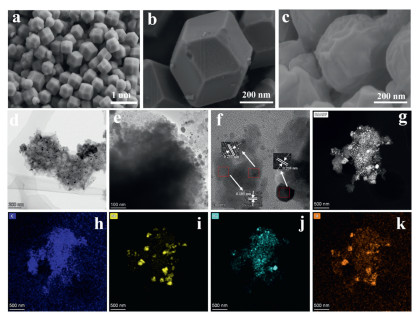
Figure 1.
SEM images of (a) ZIF8, (b) ZIF8@RuNb and (c) Ru@Nb2O5@NC. (d, e) TME images, (f) HRTEM images, (g-k) element mapping images of Ru@Nb2O5@NC.

Dual catalytic active sites Ru@Nb2O5@NC kinetically boosted polysulfide redox reaction and catalytic conversion for robust lithium sulfur batteries
Peng Yang , Chaofeng Lin , Jian Zhou , Ling Meng , Yufei Zhang , Haosen Fan


The development of innovative energy storage systems has become critically important, driven by the dual challenges of escalating environmental degradation and the global demand for sustainable energy alternatives [1–4]. Lithium-ion batteries have revolutionized energy storage solutions across transportation, consumer electronics and grid-scale applications. But their development is encountering these constraints such as low theoretical capacity of cathodes and scarcity of lithium sources. Recently, lithium-sulfur batteries (LSBs) are considered one of the most promising candidates for next-generation energy storage systems, owing to their abundant sulfur reserves, high theoretical capacity (1675 mAh/g) and high energy density (2600 Wh/kg) [5]. Despite their immense potential, the commercialization of LSBs is severely constrained by several critical issues, which include the low electrical conductivity of sulfur and lithium sulfide (Li2S) [6], the dissolution and shuttling of lithium polysulfides (LiPSs) [7] and significant volume expansion during charge-discharge processes. Among these challenges, the sluggish reaction kinetics of the reversible LiPSs conversion process and the severe ’shuttling’ of intermediate products are particularly detrimental [8], as they directly degrade the electrochemical performance and service life of LSBs [9].
To address these issues, numerous strategies have been proposed to tackle the challenges associated with LSBs, such as designing various composite sulfur cathode materials [10], lithium anode protective layers [11], and modified electrolytes in LSBs [12]. Among them, the selection of sulfur main materials, Sulfur melt dispersion and distribution are the key factors to restrict its application [13]. An effective strategy is to confine sulfur or LiPSs within the cathode host material through physical adsorption and chemical anchoring [14]. Although existing studies have demonstrated that sulfur host materials can effectively suppress lithium polysulfide (LiPSs) shuttling through physical-chemical confinement, the dissolved LiPSs species still undergo solubility-driven diffusion into the electrolyte under the combined effects of electrochemical polarization and concentration gradients [15]. This process leads to the progressive deposition of lithium polysulfides (LiPSs) on the separator surface, where the micron-scale pores (> 100 nm) in conventional polypropylene (PP) separators fail to provide effective size exclusion [16]. More critically, due to its low conductivity and surface inertness, the polypropylene (PP) separator causes the accumulated lithium-sulfur batteries in the electrolyte to become "dead sulfur" due to the loss of contact with the electrode materials, thereby leading to a decrease in battery capacity [17]. Feng et al. proposed a novel dual-layer functionalized separator strategy, consisting of an atomically dispersed CoN4-decorated Ketjen black (Co/CoN4@KB) layer and an ultrathin 2D Ti3C2Tx MXene layer. The stacked MXene layer serves as a microscopic barrier that physically blocks and chemically anchors LiPSs escaping from the pores of the Co/CoN4@KB layer, thereby confining LiPSs within highly efficient "anchoring-conversion" reaction interfaces to balance the accumulation of "dead sulfur" and Li2S [18].
In recent years, various coatings have been employed to modify the separator, aiming to mitigate the migration of lithium polysulfides (LiPSs) and activate "dead sulfur". Transition metals (e.g., Co, Ni, Fe) are widely used in catalysis, and their incorporation into separators enhances catalytic efficiency [19,20]. For instance, Zhang et al. designed a unique cobalt-based SAC with a Co-O2N2 coordination structure, where N-coordinated Co single atoms anchored on a porous carbon framework (Co/NOC) effectively capture LiPSs and significantly catalyze the bidirectional polysulfide conversion [21]. Wang et al. prepared FeS2 encapsulated in N/S co-doped bamboo-like carbon nanotubes (FeS2/NSC) through pyrolysis vulcanization and employed it as a coating separator for lithium-sulfur batteries (LSBs). The one-dimensional (1D) sulfur and nitrogen co-doped carbon matrix material serves as a conductive network, exposing more adsorption sites to enhance the trapping of lithium polysulfides (LiPS), while FeS2 enables rapid catalytic conversion of LiPS [22].
Wang et al. synthesized a novel nickel/cobalt metal-organic framework composite electrocatalyst (Ni/Co-MOF) anchored on a highly dispersed amino-functionalized MXene (Ti3C2—NH2) substrate. The Ni/Co-MOF@TCN exhibits moderate binding strength for LiPS adsorption/dissociation, enabling both Ni and Co to effectively promote the kinetics and thermodynamics of bidirectional LiPS conversion [23]. ZIF-8 is a typical zeolitic imidazolate frameworks which exhibits simple synthesis and cheap raw material and possesses a well-defined polyhedral structure. But it shows limited effectiveness in blocking polysulfides, which effectively blocks polysulfides. Additionally, the incorporation of polar elements such as sulfur, oxygen, phosphorus, and nitrogen into the matrix can significantly suppress the shuttle effect [24]. Chen et al. rationally designed and utilized ionic liquids (ILs) as dopants to synthesize N, F, B co-doped porous hollow carbon nanocages with high Ni and Fe doping (NFB-NiFe@NC), effectively enhancing the redox kinetics in lithium-sulfur batteries and suppressing the shuttle effect [25]. Luo et al. successfully synthesized one-dimensional CuCo dual-doped nitrogen-carbon nanotubes (CuCo-NC) and employed them as a modified separator layer. The incorporation of CuCo-NC increases the number of active sites, enhances lithium polysulfide (LiPS) trapping, and accelerates conversion kinetics. The synergistic effect of CuCo-NC optimizes the electronic structure, reduces the energy barrier for LiPS conversion reactions, and significantly improves catalytic activity [26]. In recent years, the incorporation of three-dimensional structured nanoparticles has effectively increased the adsorption sites for lithium ions on the electrode surface and reduced the transport path for these ions. Building on this, metal alloys exhibiting synergistic catalytic effects have been utilized to modify the separator, thereby enabling rapid reactions. Alhajji et al. constructed an independent laser-scribed graphene (LSG) interlayer, and this three-dimensional structured interlayer effectively suppresses the polysulfide shuttle in LSBs [27]. He et al. successfully designed a battery with a functional separator composed of 1T-LixMoS2/HC3N4/PP through a catalytic strategy utilizing "electron-Li+" phase reconstruction. This battery demonstrates outstanding long-term electrochemical performance [28]. Zhang et al. employed an alloying strategy to modulate the d-band structure, designing a cobalt (Co)-nickel (Ni) catalyst encapsulated within nitrogen-doped carbon nanotubes. Through d-orbital hybridization between Co and Ni, the d-band center of the CoNi catalyst was precisely tuned to an optimal position. This unique configuration enables moderate adsorption and desorption of lithium polysulfides (LiPS) on the catalyst surface, thereby achieving a balanced "adsorption-reduction-oxidation" process for sulfur species [29]. In addition, introducing precious metals such as ruthenium and iridium into the modified separator promotes the reaction kinetics of polysulfide conversion. Although precious metals like platinum, ridium, ruthenium, rhodium, and osmium are widely used for hydrogen evolution and oxygen evolution, their application in LSB research is relatively limited [30]. Among them, ruthenium (Ru), the lowest-priced platinum group metal, exhibits excellent catalytic properties and holds significant application potential in fields such as electrocatalysis and lithium-sulfur batteries. Yuan et al. designed a Ru-RuO2-x heterostructure rich in oxygen vacancies, which endowed the surrounding nanofibers with abundant active sites and ingeniously adjusted the density of states (DOS) distribution near the Fermi level, thereby promoting continuous reactivation and enhancing conductivity [31]. Although Ru exhibits excellent performance, the high cost of pure metallic Ru makes the preparation of bimetallic alloys a promising strategy. Inspired by these advancements, we developed a Ru@Nb2O5@NC modified separator material, aiming to enhance the performance of LSBs through both catalytic effects and the suppression of LiPSs.
Herein, we have successfully prepared dual catalytic active sites Ru@Nb2O5@NC heterostructure through chemical etching and ion exchange of ZIF-8 precursor. The redox reaction kinetics were significantly enhanced through systematic design and optimization of two-component active sites. In addition, the introduction of trace ruthenium into the catalyst can not only reduce the amount of noble metal, but also widen the active center of the catalyst and control its electronic structure. The underlying enhancement mechanism of the electrochemical properties was thoroughly investigated. When applied as a coating layer on the commercial PP separator, the composite demonstrates exceptional catalytic activity, superior adsorption capability, and remarkable electrochemical performance. These advantages endow the battery with an outstanding initial specific capacity of 1380.52 mAh/g at 0.2 C, along with excellent cycling stability showing only 0.099% capacity decay per cycle over 500 cycles at 0.5 C. Even at high current densities of 3 C, the Ru@Nb2O5@NC-modified battery maintains a high specific capacity of 646.77 mAh/g. Moreover, the system exhibits exceptional cycling stability and capacity retention when the sulfur loading is increased from 2.048 to 2.944 mg/cm2. This strategy presents an effective approach to enhance the performance of high-sulfur-loading lithium-sulfur batteries (LSBs), potentially accelerating their commercialization process.
The synthetic process of Ru@Nb2O5@NC is schematically shown in Fig. S1 (Supporting information). Firstly, ZIF-8 was successfully synthesized through co-precipitation method using zinc nitrate hexahydrate and 2-methylimidazole. ZIF-8 was used as the host framework for dispersing Nb5+ and Ru3+ ions. After 2 h of agitation, the powdered ZIF8-metal salt composite was collected by freeze-drying the suspension. Finally, Ru@Nb2O5@NC was obtained by sintering the ZIF-8@RuNb at 800 ℃ for 2 h under argon atmosphere. During the annealing process, Nb2O5 and Ru were encapsulated into the ZIF-8 derived carbon frameworks to prepare Ru@Nb2O5@NC nano-polyhedron heterostructure. The specific contents of Ru and Nb in the Ru@Nb2O5@NC sample were determined by ICP technique (Fig. S12 in Supporting information). This distinctive structure provides numerous double active sites that facilitate bifunctional catalysis and effectively anchor lithium polysulfides (LiPSs). When incorporated into a polypropylene (PP) separator, the Ru@Nb2O5@NC-modified separator significantly enhances LSBs performance through three mechanisms: Serving as the physical barrier for LiPSs; mitigating electrode volume expansion during cycling and suppressing the shuttle effect through promoting sulfur redox kinetics.
As shown in Fig. 1, the SEM images display the sample’s morphology and structure across varying magnifications. In Fig. 1a and Figs. S4a and b (Supporting information), it is evident that rhombic dodecahedral ZIF8 with smooth surfaces and a regular dodecahedron structure with the average diameter of about 500 nm has been successfully synthesized. After the reaction in water, the etched Nb-ZIF8 etched by Ru is depicted in Fig. 1b and Figs. S4c and d (Supporting information). As shown in Fig. 1c and Figs. S4e and f (Supporting information), the Ru@Nb2O5@NC composite adopts a well-defined core-shell architecture with a uniform particle size distribution centered at 400 nm. Figs. S4g-i (Supporting information) present the SEM image of Nb2O5, revealing it to be a loose and porous material. A clear comparison reveals that the structure of Ru@Nb2O5@NC is more compact than that of Nb2O5, and it possesses smaller pore sizes, which provides significant suppression capability against LiPS.
TEM analysis was performed to examine the detailed and inner microstructural characteristics of the sample (Figs. 1d and e, Figs. S3a and b in Supporting information). Fig. 1d and Figs. S3a and b show the porous structure of the nano-polyhedron. The TEM images of Ru@Nb2O5@NC reveal numerous metal nanoparticles uniformly dispersed within the nano-polyhedral framework. This porous architecture provides both abundant active sites and adequate storage space, facilitating efficient Li⁺ ion transport channels [32,33]. Fig. 1e and Fig. S3b clearly show the structure of the carbon films, which has an average thickness of 2 nm. High-resolution transmission electron microscopy (HRTEM) analysis in Fig. 1f reveals well-defined lattice fringes with spacings of 0.195, 0.233, and 0.178 nm, corresponding to the (102) plane of carbon, (110) plane of niobium, and (100) plane of ruthenium, respectively. Fig. 1g presents the high-angle annular dark-field scanning transmission electron microscopy (HAADF-STEM) image, clearly demonstrating the porous architecture. In addition, the EDS spectra (Figs. 1h-k) indicate that elements such as Nb, Ru, C, and O are uniformly distributed within the Ru@Nb2O5@NC nanomaterial.
The crystal structure and chemical composition were characterized by X-ray diffraction (XRD) and X-ray photoelectron spectroscopy (XPS). Fig. S4a presents the XRD pattern of Ru@Nb2O5@NC, showing characteristic diffraction peaks corresponding to both metallic Ru (PDF #06–0663) and Nb2O5 (PDF #32–0711), confirming the successful formation of the composite material. It can be observed that the positions and intensities of some diffraction peaks of Ru@Nb2O5@NC have changed compared to those of Ru and Nb2O5, which may be related to the heterogeneous structure. Fig. S4b displays the measured spectra, including the elements C, Ru, Nb, and O, further confirming the XRD spectral results. The C 1s spectrum and Ru 3d spectrum (Fig. S4c) indicate peaks at 284.8 and 280.5 eV, corresponding to C—C and Ru 3d5, respectively. The O 1s spectrum (Fig. S4d) is decomposed by Gaussian fitting into three peaks (expressed as O1, O2 and O3) followed by peaks at 531.1, 533.3 and 534.9 eV. O1 components are assigned to metal oxygen bonds, O2 components are assigned to oxygen ions, and O3 components are assigned to physical and chemical water on the surface of active materials. Fig. S4e displays the high-resolution XPS spectrum of Ru 3p, with deconvoluted peaks at 461.7 and 464.2 eV corresponding to Ru(0) and Ru(Ⅳ) species, respectively. Additionally, the Ru 3p3/2 binding energy appearing at 462 eV, with the Ru 3p1/2 peak located at 484 eV, indicates the presence of a small amount of Ru4+ in the form of RuO2. Moreover, RuO2 can provide excellent oxygen evolution reaction (OER) active sites, and its synergistic interaction with Nb2O5 can optimize the electronic structure.The Nb 3d XPS spectra in Fig. S4f have two peaks at 207.9 and 210.7 eV, which correspond to peaks at Nb 3d5/2 and Nb 3d3/2, respectively.
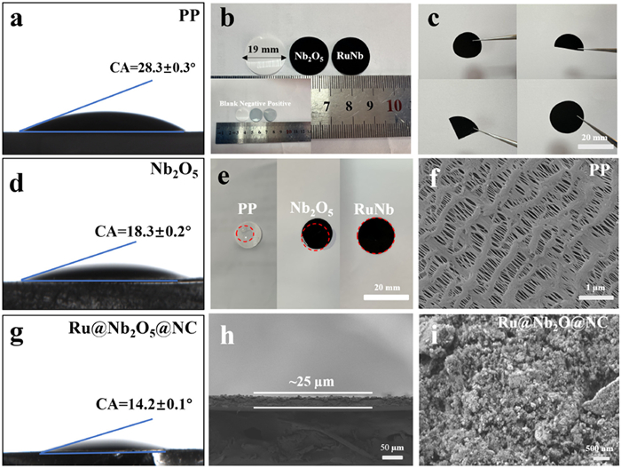
To validate the physical properties improvement of separator, a series of experiments were designed as follows. As can be seen from Figs. 2a, d and g, the PP separator exhibited the worst wettability at 28.3°±0.3°, while Nb2O5 and Ru@Nb2O5@NC exhibited better electrolyte affinity. The modified separator exhibited better performance at the contact angles of 18.3°±0.2° and 14.2°±0.1°, respectively. Fig. 2e demonstrates the wetting behavior of the separator surface upon deposition of an electrolyte droplet (~25 μL). It can be seen that the modified separator has a strong affinity for the electrolyte, that is, the contact effect, which highlights the role of the modified separator and electrolyte. Fig. 2b shows the size of the separator, indicating that each separator is 19 mm in diameter and is black on the coated surface and white on the uncoated surface. As can be seen from the folding test (Fig. 2c), the modified material has good adhesion to the PP separator and does not fall off before and after folding. To further investigate the surface morphology of the modified separator, SEM images of the improved separator and PP separator are shown in Figs. 2f, h and i. Figs. 2f and i show the positive SEM images of the PP (pristine polymer) separator and the modified separator, respectively. The PP separator exhibits a large number of pores (Fig. 2f), whereas the Ru@Nb2O5@NC-modified material is uniformly distributed on the surface of the modified separator (Fig. 2i). Notably, the modified separator exhibits smaller pore sizes compared to the conventional PP separator, contributing to effective mitigation of the polysulfide shuttle effect. Fig. 2h shows the separator thickness measurement, confirming an average thickness of 25 μm.
As shown in Figs. 3a and c, the CV value of the Ru@Nb2O5@NC-modified separator battery has two distinct cathode peaks at 2.21 and 1.94 V, corresponding to the conversion of S to long-chain soluble LiPSs (Li2Sx, 4 ≤ x ≤ 8) and further to insoluble Li2S/Li2S2, respectively. Conversely, 2.47 V anode peak is caused by reverse oxidation of Li2S/Li2S2 to S. Moreover, all batteries exhibited two reduction peaks and one oxidation peak. Notably, the Ru@Nb2O5@NC-modified separator battery exhibited a distinct advantage, with its reduction and oxidation peaks shifting to higher and lower potentials, respectively. This observation confirms that synergistic catalysis accelerates the reaction kinetics, endowing the system with superior performance compared to conventional separator materials. Figs. 3b and d depict the cyclic voltammetry (CV) curves for the initial three cycles at a scan rate of 0.1 mV/s. The highly overlapping curves across these cycles demonstrate robust stability. This electrochemical behavior demonstrates that the Ru@Nb2O5@NC-modified separator battery exhibits enhanced reaction kinetics and greater capacity potential compared to conventional systems. Figs. 3e and f display the CV curves of Ru@Nb2O5@NC//PP and Nb2O5//PP at different scan rates (0.1–0.5 mV/s). With the increase in the scan rate, the cathodic and anodic peaks on the CV curve correspondingly increase, with no significant changes in the position and shape of the peaks. Based on the cyclic voltammetry data and Randles-Sevcik equation analysis [34,35]:
|
|
(1) |
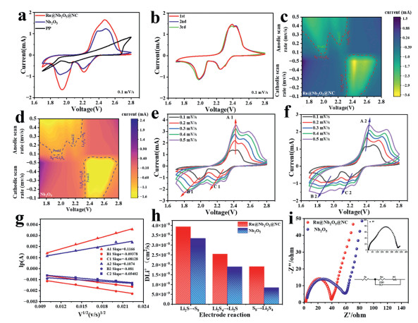
In this context, IP represents the peak current, n denotes the number of electrons transferred during the charge-discharge process (where n = 2 for LSBs), A signifies the cathode area, CLi+ indicates the concentration of Li+ in the electrolyte, and v refers to the scan rate. Evidently, the slope of the fitted curve is proportional to DLi+; thus, in this equation, only IP and v1/2 are variables. Consequently, a high slope indicates enhanced diffusion of lithium ions, which facilitates the conversion of sulfur and polysulfides [36]. In Figs. 3g and h, the peak currents corresponding to the cyclic voltammetry (CV) curves, as well as the slopes of the lithium ion (DLi+) diffusion coefficients, are presented. The observed enhancement of the ion diffusion coefficients during both the reduction and oxidation reactions highlights the influence of ruthenium (Ru) introduction on these reactions. The Ru@Nb2O5@NC-modified separator battery demonstrates a steeper slope compared to the control sample, with the maximum DLi+, further confirming the significance of the heterostructure in facilitating the catalytic conversion of polysulfides into insoluble Li2S2 and ultimately into the final product, Li2S. The Nyquist plot (Fig. 3i) reveals that the Ru@Nb2O5@NC-modified battery has the smallest impedance across all frequency regions, outperforming both Nb2O5//PP and PP batteries.
We further systematically evaluated the rate performance of all assembled batteries through charge/discharge cycling at various current densities with five cycles at each current step (Fig. 4a). It is impressive that the battery based on Ru@Nb2O5@NC//PP exhibits a high rate performance of 651.7 mAh/g even at a 3 C rate, outperforming Nb2O5 (490.3 mAh/g at 3 C), Ru@NC(357.4 mAh/g at 3 C) (Fig. S14a in Supporting information) and the PP battery (198.3 mAh/g at 3 C). The primary reason lies in the enhanced electronic/ionic transport properties of the material, which improve charge transfer efficiency and ion transport performance. When the current density was restored to 0.2 C, the average discharge capacity reached 1186.3 mAh/g, indicating excellent reversibility of the redox reaction. However, batteries based on Nb2O5//PP and PP battery only provide average recovery capacities of 1082.3 and 923.6 mAh/g, respectively. As shown in Fig. S13 (Supporting information), compared with most reported separator systems, the battery equipped with the Ru@Nb2O5@NC modified separator delivers superior rate performance, clearly demonstrating the synergistic advantages of Ru@Nb2O5@NC in regulating polysulfide species and enhancing electrochemical reaction kinetics. Fig. 4b shows the charge-discharge curves of Ru@Nb2O5@NC-modified separator battery at different current densities. As the current density increases, the discharge platform becomes shorter, confirming the fast reaction kinetics of the Ru@Nb2O5@NC-modified separator. At the same time, the voltage platform of the charge-discharge curve corresponds to the front-end position of the cyclic voltammetry curve in Fig. 4a. Fig. S5 (Supporting information) displays the charge-discharge curves of Nb2O5//PP and PP batteries, which are significantly inferior to those of the Ru@Nb2O5@NC-modified separator battery. Additionally, the first cycle of constant current charge-discharge process is illustrated in Fig. 4d, demonstrating that Ru@Nb2O5@NC-modified separator battery maintains a smaller polarization potential compared to Nb2O5//PP and PP separator. This result provides strong evidence that the synergistic catalysis of the dual components accelerates the reaction rate.
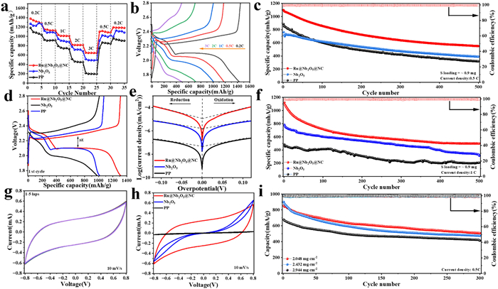
To confirm the long-term cycling performance, batteries assembled with various separators were tested at 0.5 and 2 C for 500 cycles (Figs. 4c and f). Fig. 4c and Fig. S6 (Supporting information) display the long-cycle performance tests at 0.5 C with an S loading of 0.896 mg. Notably, Ru@Nb2O5@NC-modified separator battery delivers a high initial discharge specific capacity of 1098.87 mAh/g at 0.5 C, with a decay rate of 0.099% per cycle over 500 cycles. In contrast, the batteries assembled with other separators exhibit decay rates of 0.128% and 0.104% respectively, demonstrating the superior cycling stability of the Ru@Nb2O5@NC separator. Figs. S6 and S7 (Supporting information) present detailed charge-discharge curves at different cycles. Even at 1 C current density (Fig. 4f), the Ru@Nb2O5@NC-modified separator battery exhibited exceptional cycling stability, showing an ultralow capacity decay rate of 0.11% per cycle over 500 cycles. Fig. S14b (Supporting information) demonstrates the cycling performance of the Ru@NC//PP battery at 0.5 C and 1 C, which is significantly lower than that of the Ru@Nb2O5@NC modified separator battery. Notably, Compared to unmodified batteries, unequivocally demonstrating the material’s unique structural advantages and superior catalytic activity in the adsorption-catalysis-desorption process. Additionally, Fig. 4i illustrates sulfur loadings of 2.048, 2.432 and 2.944 mg to investigate their performance under high sulfur loading. The experimental results demonstrate that the material can maintain a high specific capacity even under high sulfur loading, with a coulombic efficiency of up to 100%. The findings reveal that the modified separator effectively suppresses the shuttle effect of polysulfides, thereby preventing the volume expansion of lithium-sulfur batteries. Additionally, the electrochemical performance of the battery under high sulfur loading (Fig. S15 in Supporting information) was evaluated. With a sulfur loading of 4.16 mg/cm2 and an electrolyte to sulfur (E/S) ratio of 7 μL/mg, the battery exhibited a high areal capacity of 4.1 mAh/cm2 at 0.5 C. Furthermore, the material demonstrated excellent capacity retention and cycling stability over 100 charge-discharge cycles, indicating good electrochemical stability.
Fig. 4g shows the cyclic voltammetry (CV) curves of Ru@Nb2O5@NC-modified separator for the first five cycles at 10 mV/s, demonstrating excellent stability, which indicates that the Ru@Nb2O5@NC material plays a crucial role in the conversion of LiPSs. As shown in Fig. 4h, the CV curves measured at a scan rate of 10 mV/s reveal that Ru@Nb2O5@NC exhibits the highest peak current among the tested materials. The Tafel plot was obtained to reveal the electrocatalytic activity of Ru@Nb2O5@NC for LiPS conversion (Fig. 4e). The Tafel curve was fitted between −0.2 V and 0.2 V. The exchange current density (I0) was calculated according to the following Bulter-Volmer formula [37]:
|
|
(2) |
Among them, η is a constant, b is the Tafel slope, η is the overpotential, and I is the response current of the symmetric cell. Ru@Nb2O5@NC exhibits the highest maximum I0 of 0.732 mA/cm2 during the reduction and oxidation processes, outperforming Nb2O5 (0.526 mA/cm2) and PP (0.498 mA/cm2). Additionally, the Ru@Nb2O5@NC based battery exhibits a lower Tafel slope value, demonstrating excellent catalytic capability in promoting the kinetics of conversion reactions. To investigate the role of the Ru@Nb2O5@NC-modified separator in regulating lithium deposition, lithium symmetric cells were fabricated with different separators. The cell employing the Nb2O5 separator showed an initial overpotential of ~40 mV under 2 mA/cm2 and 2 mAh/cm2 (Fig. S8a in Supporting information). After 50 h of stable deposition/stripping, the overpotential gradually increased with the number of cycles until reaching the cutoff voltage at the 300 h cycles (Fig. S9e in Supporting information). Li//Li symmetric cells, due to their excessively high charge and discharge rates, lead to rapid loss of electrolyte and metallic lithium, increased side reactions, and enhanced polarization during the charge and discharge processes, resulting in their inability to function properly within a short period of time [38]. However, the Li//Li symmetric cell constructed with the Ru@Nb2O5@NC separator maintained a high overpotential even after 800 charge-discharge cycles (Figs. S8a and S9c in Supporting information). It demonstrates that Ru@Nb2O5@NC can effectively regulate lithium deposition and suppress the excessive growth of lithium dendrites. Fig. S8b (Supporting information) shows the microstructure of the cycled lithium metal. Even after prolonged cycling (900 h), a dense SEI film is observed on the lithium metal surface.
Nucleation experiments were conducted to demonstrate the modified material’s role in accelerating redox kinetics. The experimental setup comprised a cathode of Ru@Nb2O5@NC and polyvinylidene fluoride (PVDF) (9:1 mass ratio), a pure Celgard 2400 separator, lithium foil as the anode, and Li2S8 as the electrolyte, a significant deviation from conventional batteries. To ensure complete conversion of Li2S8 to Li2S4, the cell was first discharged at a constant current of 0.112 mA until the voltage reached 2.06 V. Subsequently, a constant-voltage discharge at 2.05 V was applied until the current fell below 10−5 mA. Figs. 5a and b display the experimental results. According to previous studies relating peak current to scan rate [39,40]:
|
|
(3) |
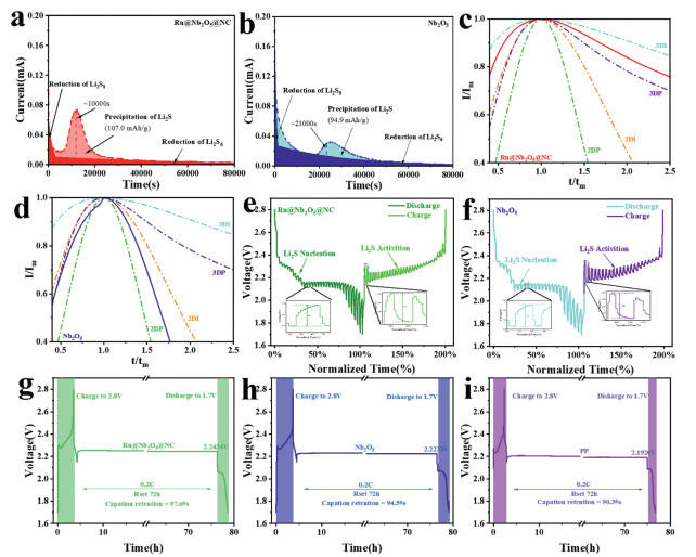
In the equation, tm represents the peak current time (s), A is the nucleation rate constant (cm2/s), and k denotes the growth rate (cm/s). The reaction kinetics, characterized by the peak current, nucleation site density, and nucleation time, show a clear acceleration trend. The Li2S based on Ru@Nb2O5@NC shows extremely high current reactivity, excellent nucleation capacity, and excellent 107 mAh/g nucleation capacity, higher than Nb2O5//PP batteries. In the experimental process of Ru@Nb2O5@NC, the nucleation time was shortened, the peak current was larger and the peak area was larger, which showed that Ru@Nb2O5@NC//PP heterojunction had synergistic effect. Figs. 5c and d present the normalized current (i/im) versus normalized time (t/tm) curves for different separator systems, analyzed using four nucleation models: Two-dimensional instantaneous (2DI), two-dimensional progressive (2DP), three-dimensional instantaneous (3DI), and three-dimensional progressive (3DP) [41].
In Fig. 5c, the experimental data initially align with the 3DI model before transitioning to the 2DP model at longer time scales, suggesting a hybrid nucleation mechanism. This behavior indicates that Li2S deposition is initially governed by rapid 3D instantaneous nucleation, followed by progressive 2D growth. Such a mechanism implies that the Ru@Nb2O5@NC separator provides abundant active sites and strong interfacial catalytic activity, facilitating both fast nucleation and uniform Li2S deposition. In contrast, Fig. 5d primarily fits the 3DP and 2DP models, reflecting slower 3D progressive nucleation and less uniform deposition behavior. This difference highlights the critical role of the modified separator in enhancing the kinetics and uniformity of L2S formation. The conventional electrochemical deposition mechanisms typically involve two distinct modes: Two-dimensional (2D) and three-dimensional (3D) nucleation, which can be further categorized as progressive nucleation. As illustrated in Fig. 5c, Li-CP cells incorporating EtV2+ demonstrate a 3D instantaneous (3DI) nucleation mode for Li2S deposition. This observation suggests a significantly enhanced nucleation rate compared to the 2D instantaneous (2DI) mode observed in the absence of EtV2+ (Fig. 5d).
As shown in Figs. 5e and f, galvanostatic intermittent titration technique (GITT) was employed to evaluate the electrochemical behavior of LSBs equipped with Ru@Nb2O5@NC//PP (Fig. 5e) and Nb2O5//PP (Fig. 5f) separators at 0.1 C. The constant-current charge-discharge profiles exhibit two distinct voltage plateaus along the time axis, corresponding to the Li2S nucleation (~50% state of charge) and activation (~100% state of charge) stages. Notably, compared to the Nb2O5-modified separator cell, the Ru@Nb2O5@NC-modified separator cell exhibited significantly reduced voltage polarization and more stable voltage transitions during both critical stages. This improvement suggests enhanced interfacial catalytic activity and more efficient electron transfer kinetics in the Ru@Nb2O5@NC modified system. Figs. 5g-i present the constant-current charge-discharge profiles recorded at 0.2 C (charge cutoff: 2.8 V; discharge cutoff: 1.7 V) after 72 h of operation for cells equipped with different separator materials. The Ru@Nb2O5@NC//PP (Fig. 5g) demonstrates superior performance, maintaining 97.6% of its initial capacity while exhibiting a stable discharge plateau at approximately 2.24 V. In comparison, cells utilizing Nb2O5//PP (Fig. 5h) and polypropylene (PP) (Fig. 5i) separators show lower capacity retention rates of 94.5% and 90.3%, respectively, with corresponding discharge plateaus at 2.223 and 2.192 V. These results clearly demonstrate that the Ru@Nb2O5@NC composite separator effectively suppresses polysulfide shuttle through synergistic mechanisms combining physical adsorption and interfacial catalysis [42]. This dual functionality not only minimizes active material loss but also significantly enhances both the cycling stability and electrochemical reaction kinetics of the LSBs system.
To investigate the atomic anchoring stability and electronic structure modulation of isolated Ru atoms on the Nb2O5 carrier, systematic density functional theory (DFT) calculations were conducted for two models, Ru@Nb2O5@NC and Nb2O5 (Figs. 6a–f). By optimizing its structure (Figs. 6a and d), the Ru@ Nb2O5@NC system has stable coordination between Ru and Nb2O5 compared to the Nb2O5 structure and is coated with a carbon film to create a three-dimensional coordinated environment with high anchoring performance and spatial stability. To further explore the differences between the two systems, a charge density difference (CDD) analysis was performed (Figs. 6b and e). In a charge differential density diagram, the yellow region represents electron accumulation and the blue region represents electron depletion [43]. Fig. 6b shows significant charge accumulation and depletion at the Ru/Nb2O5 interface, with charge transfer from Nb2O5 to Ru. This interfacial charge transfer enhances the bonding interaction. In contrast to the single Nb2O5 in Fig. 6e, electrons accumulate internally but cannot be delocalized to compensate for external electron depletion. Thus, the redistribution of charge and overlap of electron clouds lead to stronger interactions at heterogeneous interfaces. State density (DOS) describes the distribution of electron energy states in materials (Figs. 6c and f). It is noteworthy that the significant overlap between the contributions of Ru@Nb2O5@NC near the Fermi level (~ 0 eV) Ru and Nb2O5 indicates strong electron coupling, which facilitates the formation of charge transport and active catalytic centers. Conversely, a single Nb2O5 exhibits relatively low DOS at the Fermi level, indicating limited electron interaction and poor conductivity. Ru@Nb2O5@NC heterostructures contribute significantly more to DOS of −9 eV to −7 eV over the entire energy scale than a single Nb2O5. Ru contributes significantly more over a wider energy range, resulting in accelerated ion transport. In summary, the Ru@Nb2O5@NC composite is shown to outperform Nb2O5 in terms of structural integrity, electronic coupling, and ionic conductivity, highlighting its potential as a functional separator coating for lithium sulfur batteries. Therefore, the chemical principle innovation of Ru@Nb2O5@NC lies in the multi-component synergy (adsorption + catalysis + conductivity) rather than a single function; the interfacial electronic engineering (Ru-Nb2O5 charge redistribution) enhances intrinsic activity; and the full-chain design covers the adsorption, conversion of LiPS, and the deposition/decomposition of Li2S.
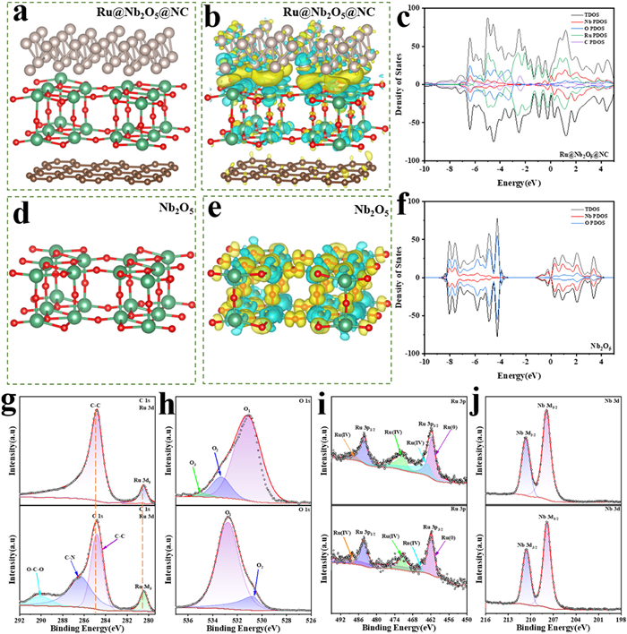
Figs. S10a and b (Supporting information) demonstrate the adsorption of Li2S6 on the modified materials, as evidenced by the decolorization of the yellow polysulfide solution after the reaction. Furthermore, XPS analysis of the adsorbed material Fig. S10c in Supporting information) demonstrates the presence of two additional peaks corresponding to S 2p and F 1s, providing direct evidence for the successful adsorption of Li2S6 on the target material. Furthermore, high-resolution XPS spectra (Fig. S10d in Supporting information and Figs. 6g-j) show significant positive shifts in the binding energies of O 1s, Ru 3p, S 2p, and Nb 3d, confirming the chemical interaction between the target material and Li2S6. Further confirmation from the high-resolution S 2p XPS spectrum (Fig. S10d) reveals four distinct peaks located at 169.50 eV (S-O), 168.05 eV (S 2p1/2), 167.45 eV (S 2p3/2), and 164.35 eV (M-S). Additionally, the O 1s peak at 534.90 eV (Fig. 6h) shows significant attenuation compared to the untreated material, Oxygen plays an important role in adsorption. The accumulated evidence supported the conclusion that Ru@Nb2O5@NC interacts with Li2S6 and exhibits enhanced performance in inhibiting the shuttle effect and accelerating the reaction kinetics of polysulfides.
To visually assess the shuttle effect, we conducted a polysulfide permeation experiment using three separators (Fig. S11 in Supporting information). A yellowish-brown solution was prepared by dissolving Li2S6 in a 1:1 (v/v) mixture of 1,3-dioxolane (DOL) and dimethoxyethane (DME), while the opposite compartment contained only the DOL/DME solvent. Over 0–24 h, in PP separator, shuttle phenomenon is most serious. The other two separators initially suppressed polysulfide migration effectively within 6 h but showed deterioration after 12 h. In contrast, the Ru@Nb2O5@NC system maintained significantly higher solution transparency, demonstrating effective polysulfide shuttle suppression and enhanced redox kinetics.
In summary, Ru@Nb2O5@NC heterostructure with Ru and Nb2O5 double catalytic active sites hetero-nanocrystals were successfully prepared via successive coprecipitation, chemical etching and high-temperature pyrolysis processes. Furthermore, the porous structured Ru@Nb2O5@NC provides abundant active sites, facilitating rapid ion diffusion and enhanced redox kinetics. exhibiting stable structural integration with the separator. At 0.5 C, Ru@Nb2O5@NC demonstrated a low capacity decay rate of 0.099% per cycle over 500 cycles, retaining a discharge capacity of 651.70 mAh/g even at 3 C. Under a higher current density of 1 C, the decay rate further decreased to 0.11% after 500 cycles. Remarkably, the system maintained superior battery performance under high sulfur loadings (506.67 mAh/g at 2.0488 mg/cm2, 475.09 mAh/g at 2.432 mg/cm2, and 423.61 mAh/g at 2.944 mg/cm2 after 300 cycles), while achieving near-100% Coulombic efficiency. This work provides new insights into enhancing lithium-sulfur battery (LSB) performance through synergistic integration of polysulfide chemical adsorption and catalytic conversion enabled by advanced separator modification.
Peng Yang: Writing – original draft, Investigation. Chaofeng Lin: Formal analysis. Jian Zhou: Software. Ling Meng: Writing – review & editing, Supervision. Yufei Zhang: Writing – review & editing, Supervision. Haosen Fan: Writing – review & editing, Supervision.
The authors declare that they have no known competing financial interests or personal relationships that could have appeared to influence the work reported in this paper.
This work was supported by National Natural Science Foundation of China (Nos. 22208069, 52472194, 52101243), Natural Science Foundation of Guangdong Province, China (Nos. 2025A1515012571, 2025A1515010345, 2023A1515012619) and the Science and Technology Planning Project of Guangzhou (No. 202201010565). We would like to thank Analysis and Test Center of Guangzhou University for their technical support (XRD PW3040/60).
Supplementary material associated with this article can be found, in the online version, at doi:
H.J. Liang, X.T. Li, X.L. Liu, et al., J. Power Sources 517 (2022) 230729. doi: 10.1016/j.jpowsour.2021.230729
R. Sun, P. Xia, X.C. Guo, et al., Chem. Eng. J. 486 (2024) 150377. doi: 10.1016/j.cej.2024.150377
Q.X. Deng, X.L. Liu, Z.Y. Li, et al., J. Colloid Interface Sci. 633 (2023) 480–488. doi: 10.1016/j.jcis.2022.11.083
S.M. Wu, Y.N. Li, L.T. Chen, et al., Chin. Chem. Lett. 36 (2025) 109796. doi: 10.1016/j.cclet.2024.109796
X.Y. Jin, X.C. Guo, S.Y. Dong, et al., Chin. Chem. Lett. 36 (2025) 110604. doi: 10.1016/j.cclet.2024.110604
A. Nazir, A. Pathak, D. Hamal, et al., Energy Environ. Mater. 8 (2025) 118–128. doi: 10.1177/09737030251346761
J. Chen, Y. Zhang, J. Yang, et al., Sci. China Chem. 67 (2024) 106–121. doi: 10.1007/s11426-022-1421-7
J. Xiong, X. Liu, P. Xia, et al., J. Colloid Interface Sci. 652 (2023) 1417–1426. doi: 10.1016/j.jcis.2023.08.185
Z. Xu, H. Xu, J. Sun, et al., Trans. Tianjin Univ. 29 (2023) 407–431. doi: 10.1007/s12209-023-00373-y
R. Deng, M. Wang, H. Yu, et al., Energy Environ. Mater. 5 (2022) 777–799. doi: 10.1002/eem2.12257
Z. Xu, H. Xu, J. Sun, et al., Trans. Tianjin Univ. 29 (2023) 407–431. doi: 10.1007/s12209-023-00373-y
S.D. Jing, X.L. Peng, S.L. Li, et al., Chin. Chem. Lett. 36 (2025) 110732. doi: 10.1016/j.cclet.2024.110732
C. Zhou, Z. Li, X. Xu, et al., Natl. Sci. Rev. 8 (2021) 104–121. doi: 10.1117/12.2620241
Y. Wang, H. Chen, F. Yu, et al., Chin. Chem. Lett. 35 (2024) 499–505.
X.L. Peng, L. Yuan, S.L. Li, et al., J. Colloid Interface Sci. 700 (2025) 138455. doi: 10.1016/j.jcis.2025.138455
Y. Song, M. Zhou, Z. Chen, et al., Chin. Chem. Lett. 35 (2024) 109200. doi: 10.1016/j.cclet.2023.109200
D. Zhu, T. Long, B. Xu, et al., J. Energy Chem. 57 (2021) 41–60. doi: 10.1016/j.jechem.2020.08.039
J.A. Feng, C.Y. Zhang, W.D. Liu, et al., Angew. Chem. Int. Ed. 63 (2024) e202407042. doi: 10.1002/anie.202407042
X. Jiang, S. Zhao, Y. Qi, et al., Metall. Mater. 32 (2025) 1270–1282. doi: 10.1007/s12613-024-3026-1
L. Chen, Y. Liu, Y. Su, et al., Sci. China Chem. 68 (2025) 1287–1316. doi: 10.1007/s11426-024-2277-2
Y. Zhang, H. Yuan, E. Guo, et al., J. Energy Chem. 99 (2024) 604–614. doi: 10.3390/atmos15050604
M. Wang, M. Chen, W. Zhang, et al., J. Colloid Interface Sci. 690 (2025) 137298. doi: 10.1016/j.jcis.2025.137298
W. Wang, J. Si, L. Yue, et al., Chem. Eng. J. 507 (2025) 160363. doi: 10.1016/j.cej.2025.160363
X. Zuo, Y. Qiu, M. Zhen, et al., Nano-Micro Lett. 17 (2025) 119–146. doi: 10.1007/s40820-024-01644-6
X. Zhang, W. Yuan, H. Huang, et al., Int. J. Extrem. Manuf. 5 (2023) 272–286.
Y. Luo, S. Liu, M. Chen, Chem. Eng. J. 505 (2025) 159158. doi: 10.1016/j.cej.2024.159158
E.M. Alhajji, W.X. Wang, W.L. Zhang, et al., ACS Appl. Mater. Interfaces 12 (2020) 18833–18839. doi: 10.1021/acsami.0c01135
Y. He, D. Xiong, Y. Luo, et al., Adv. Funct. Mater. 35 (2024) 2410899.
W. Zhang, M. Xu, Y. He, et al., Small 21 (2025) e2502300. doi: 10.1002/smll.202502300
Y. Gong, J. Li, K. Yang, et al., Nano-Micro Lett. 15 (2023) 392–430. doi: 10.1002/ijfe.2426
Y. Tian, M. Yang, C. Wang, et al., J. Mater. Chem. A 10 (2022) 8826–8836. doi: 10.1039/d2ta01573k
H. Cheng, J. G. Shapter, Y. Li, G. Gao, et al., J. Energy Chem. 57 (2021) 451–468. doi: 10.1016/j.jechem.2020.08.056
X. Chen, B. Wang, Y. Ye, et al., Energy Environ. Mater. 8 (2025) 5–37.
L. Chen, R. Shao, C. Bao, et al., J. Anal. Test. 9 (2025) 193–201. doi: 10.1007/s41664-025-00358-x
S. Arya, A. Singh, A. Ahmed, et al., J. Energy Chem. 105 (2025) 193–223. doi: 10.1016/j.jechem.2025.01.052
C. Wu, J. Li, L. Liu, et al., Energy Environ. Mater. 6 (2023) 147–156.
X. Li, Y. Li, Y. Jiang, et al., Green Energy Environ 10 (2025) 537–550. doi: 10.1016/j.gee.2024.05.012
Y. Wu, C. An, Y. Guo, et al., Nano Micro Lett. 16 (2024) 282–348.
P.F. Wan, S.Y. Dong, J. Xiong, et al., J. Colloid Interface Sci. 650 (2023) 582–592. doi: 10.1016/j.jcis.2023.07.022
S.D. Jing, S.L. Li, X.L. Peng, et al., Chem. Eng. J. 521 (2025) 166774. doi: 10.1016/j.cej.2025.166774
D. Tian, X. Song, Y. Qiu, et al., Energy Environ. Mater. 5 (2022) 1214–1221. doi: 10.1002/eem2.12236
X. Wang, X. Wang, X. Wang, et al., Natl. Sci. Rev. 12 (2025) 49–65.
M.Y. Chen, Z.J. Yang, S.J. Lu, et al., J. Energy Chem. 122 (2026) 415–426. doi: 10.1016/j.jechem.2026.07.055

Figure 1 SEM images of (a) ZIF8, (b) ZIF8@RuNb and (c) Ru@Nb2O5@NC. (d, e) TME images, (f) HRTEM images, (g-k) element mapping images of Ru@Nb2O5@NC.

Figure 2 (a, d, g) Average water contact angles of modified separators (mean ± SD, n = 3 independent experiments. (b) Digital photo PP, Nb2O5, and Ru@Nb2O5@NC modified separator. (c) The digital photo Ru@Nb2O5@NC modified separator under different stresses. (e) Direct wettability of separators to electrolytes. (f, i) The SEM image of the surface morphology of PP and Ru@Nb2O5@NC. (h) The improved SEM photos of separator cross-section.

Figure 3 (a, c) Cyclic voltammetry (CV) profiles of three separator variants at a scan rate of 0.1 mV/s. (b, d) Initial three CV cycles. (e, f) Comparative CV profiles of Ru@Nb2O5//PP and Nb2O5//PP at varying scan rates (0.1–0.5 mV/s). (g) Peak current densities derived from CV analysis. (h) Calculated Li+ diffusion coefficients for different redox processes (mean ± SD, n = 3). (i) Electrochemical impedance spectroscopy (EIS) Nyquist plots of different separators.

Figure 4 (a) The rate performance of Ru@Nb2O5@NC//PP, Nb2O5//PP, and PP batteries. (b) Charge-discharge curves of Ru@Nb2O5@NC//PP at different current densities. (c) The cycle performance of Ru@Nb2O5@NC//PP, Nb2O5//PP, and PP batteries at 0.5 C. (d) The Galvanostatic charge/discharge curve at 0.2 C. (e) Tafel diagram of symmetric cell. (f) The cycle performance of Ru@Nb2O5@NC//PP, Nb2O5//PP, and PP batteries at 1 C. (g) The first five cyclic curves of Ru@Nb2O5@NC//PP under 10 mV/s. (h) CV Curves of Batteries with Different Symmetry at 10 mV/s. (i) The cycle performance of high S loading at 0.5 C.

Figure 5 (a, b) The nucleation kinetics of different electrodes was studied by Li2S shape verification. Dimensionless current−time transient of (c) Ru@Nb2O5@NC//PP, (d) Nb2O5//PP. GITT plots of (e) Ru@Nb2O5@NC//PP, (f) Nb2O5//PP. Self-discharge performance of cells with different separators after resting for 72 h at 0.2 C: (g) Ru@Nb2O5@NC//PP, (h) Nb2O5//PP (i) PP.

Figure 6 Schematic model of (a) the Ru@Nb2O5@NC structure and (d) the Nb2O5 structure. The charge density difference of (b) Ru@Nb2O5@NC and (e) Nb2O5. DOS of (c) Ru@Nb2O5@NC and (f) Nb2O5. (g-j) High-resolution XPS spectra showing C 1s, Ru 3d, O 1s, Ru 3p, and Nb 3d regions before and after adsorption, respectively.

 扫一扫看文章


扫一扫关注我们
 DownLoad:
 下载:
 下载: