
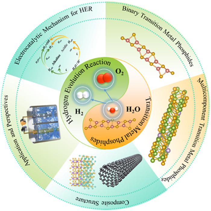
Figure 1.
Transition metal phosphide electrocatalysts for the HER.


Nowadays, most energy of the world is still dependent on fossil fuels (oil, coal, natural gas, etc.) [1–4]. This has led to an increase in the greenhouse effect and environmental pollution problems [5,6]. In this background, it is urgent to replace them with a clean energy source that enables a stable supply. Hydrogen energy is considered a central carrier for the energy transition because of its high energy density (142 MJ/kg) and zero-carbon emission properties [7,8]. Grey hydrogen and green hydrogen are two dominant current hydrogen production strategies. Gray hydrogen is a means of producing hydrogen through steam methane reforming [9]. It is low-cost but emits 10 kg CO2 for 1 kg of hydrogen produced. While gray hydrogen dominates current production. Green hydrogen via water electrolysis is the focus of this review due to its zero-carbon potent. Green Hydrogen produces hydrogen with zero carbon emissions through water electrolysis driven by renewable energy [10,11]. They represent traditional high carbon and emerging zero-carbon pathways, respectively. Although the cost of green hydrogen is high, it has become the main research direction of obtaining hydrogen energy motivated by the goal of carbon neutrality. Water electrolysis is the only zero-carbon technology route of green hydrogen, its efficiency and cost directly determine the economic viability of this process. HER is its key step, and the higher the overpotential, where elevated overpotential proportionally escalate energy consumption of water electrolysis [12–14]. Pt-based catalysts significantly reduce the overpotential of HER [15]. But they are scarce and expensive [16]. This results in their inability to meet the amount of catalyst required for industrial grade electrolyzers. Therefore, researchers are committed to developing a series of HER catalysts with abundant yield and promising activity.
Transition metal phosphides (TMPs) are compounds formed from transition metals with P element. Liu et al. found that the hydrogen adsorption energy of Ni2P is close to Pt electrode through theoretical calculation [17]. They proposed for the first time that TMPs possess HER catalytic potential. Their raw materials are abundant and cost only a thousandth of the price of Pt element [18,19]. This gives them a remarkable economic advantage in large-scale applications. However, their intrinsic activity still falls short of that of noble metal catalysts [20–22]. During prolonged operation, they suffer from phosphorus leaching and structural collapse, thereby adversely affecting the electrolytic efficiency [23–25]. Therefore, it is crucial to understand the catalytic principles of TMPs to design efficient and stable HER catalysts.
This review comprehensively sums up the fundamentals of HER, catalytic mechanisms of TMPs, and performance enhancement strategies (Fig. 1). Firstly, we describe the electrocatalytic mechanism of HER and its influence on the design of TMPs catalysts. The following segment thoroughly explores the classification, limitations, and performance improvement strategies for monometallic TMPs. Subsequent sections conclude polymetallic TMPs and composite architectures, demonstrating how multicomponent synergy enhances catalytic efficiency through interfacial engineering and electronic modulation. Finally, this review suggests future possible challenges and development directions, aiming to provide valuable reference and guidance for researchers in HER field.
HER on catalyst surface mainly includes two processes: Adsorption and desorption. The poor conductivity of pure water makes it is necessary to add alkaline or acidic ions into it to increase its charge conduction [26,27]. And electrolytes with different pH will lead to different HER working mechanisms [28]. The specific reactions in the alkaline electrolyte are as follows [29]:
|
|
(1) |
|
|
(2) |
|
|
(3) |
In Volmer step, H2O molecules are adsorbed on electrode surface and dissociate into adsorbed hydrogen atoms (Hads). The coverage of Hads on electrode surface determines whether the next step is electrochemical desorption (Heyrovsky step) or chemical desorption (Tafel step) [30]. As shown in Eq. 2, when the Hads at low coverage, it will be coupled with protons or electrons in the electrolyte to form H2. A sufficiently high Hads coverage will cause two neighboring Hads to combine on their own (Eq. 3).
The water dissociation step (Eq. 1) is a critical step of HER under alkaline conditions. This process requires the breaking of strong O-H bonds (bond energy ~492 kJ/mol). It results in inherently sluggish alkaline HER kinetics. In TMPs, the high electronegativity of P atoms attracts electrons from adjacent transition metals to them. Thus, metal sites are positively charged and P sites are negatively charged. On the one hand, positively charged metal sites elongate the O-H bond in H2O, thereby lowering the water dissociation energy barrier. Through density functional theory (DFT) calculations, Bu et al. obtained that the water dissociation energy barrier on CoP (011) crystal plane is only 0.52 eV, which is half of the reaction without catalysts (1.0–1.2 eV) [31]. On the other hand, the negatively charged P sites adsorb OH- intermediates through electrostatic interactions and weak covalent bonding. This working mechanism prevents OH- from poisoning active sites and accelerates the formation of H2. It is evident that the existence of bifunctional sites is central to high HER activity of TMPs in alkaline media. Furthermore, P-M bond is relatively resistant to OH- corrosion, so many TMPs possess outstanding long-term stability in alkaline electrolytes. Nevertheless, TMPs still feature multiple drawbacks and limitations that restrict their practical application. Firstly, electron modulation effect of P atoms on metal sites causes their hydrogen adsorption free energy (ΔGH*) to deviate from the optimal value of 0 eV. This deviation increases the overpotential and energy consumption during hydrogen production. Secondly, most TMPs expose only a limited number of edge or defect sites, resulting in their intrinsic catalytic activity being relatively low. In practical operation, TMPs catalysts face severe mass transport limitations at high current densities and high voltages (> 1.6 V) for overall water splitting. These deficiencies fundamentally restrict large-scale deployment for green hydrogen production. To address these constraints, hierarchical design strategies for TMPs have been established: (1) Fundamental investigation of monometallic phosphides, (2) atomic-scale synergy engineering in polymetallic phosphides, (3) performance maximization via composite construction. This progressive approach resolves targeted bottlenecks at each level. The following sections systematically describe design principles, performance merits, and unresolved challenges across these TMP categories.
Unlike the alkaline environment, the following procedures are required for HER in an acidic electrolyte [32]:
|
|
(4) |
|
|
(5) |
|
|
(6) |
In acidic environments, H+ adsorbs onto the catalyst and couple with electrons to form Hads. Similarly, the Hads reacts directly with H+ and e- to generate H2 in the Heyrovsky step. It does not have to undergo dissociation process of H2O molecules so that it possesses relatively fast reaction kinetics. However, acidic electrolytes tend to bring severe corrosion of catalysts [33,34]. Therefore, current researches on water electrolysis are still mainly carried out under alkaline conditions [35,36]. This review will primarily focus on the reaction mechanisms of HER in alkaline electrolytes.
Overpotential (η) serves as a fundamental kinetic parameter for evaluating the intrinsic activity of HER catalysts. Theoretically, the minimum voltage required for overall water splitting is equal to its thermodynamic reversible electromotive force [37]. But the actual processes take place in a non-standard state. This working state involves factors such as reaction activation energy, electrolyte concentration and electrolytic cell resistance [38]. For HER, the actual potential applied to the electrode (Eapplied) must deviate significantly from its thermodynamic equilibrium potential (Eeq, HER) to drive the target current density. The difference between the two is defined as the overpotential (ηHER) of HER:
|
|
(7) |
Eeq, HER shows pH dependence as described by the Nernst equation:
|
|
(8) |
This equilibrium potential is defined on the reversible hydrogen electrode (RHE) scale. Lower ηHER values indicate that the catalyst operates closer to the thermodynamic limit, signifying higher catalytic activity.
Tafel slope is the key parameter to describe HER dynamics. It can be derived from the formula proposed by Tafel in 1905 [39]:
|
|
(9) |
where j is the current density, a is a constant related to the exchange current density, and b represents the Tafel slope. The lower the b value, the less potential is required to be added to reaction when increasing the current density by the same magnitude. It is evident that Tafel slope reflects the response sensitivity of current to potential changes. In particular, it assists in estimating the rate-dependent step (RDS) and reaction mechanism of catalytic reaction. The estimation process depends on the following formula [40]:
|
|
(10) |
α is the transfer coefficient. According to the calculation, the Tafel slopes are 120, 40, and 30 mV/dec when the Volmer step (α = 0.5), Heyrovsky step (α = 1.5), and Tafel step (α = 2) are the RDS, respectively [41]. After identifying the RDS, corresponding measures are taken to reduce reaction energy barrier and improve HER efficiency. While the Volmer step is RDS, proton adsorption can be accelerated by increasing the proton concentration in the electrolyte or optimizing the electrode surface properties [42]. In the other two cases, it is necessary to adjust the hydrogen coverage on the catalyst surface to accelerate the desorption process [43,44].
The electrochemically active surface area (ECSA) reflects the number of active sites actually involved in the electrochemical reaction on the catalyst's surface. It eliminates the effect of geometrical area and thus accurately assesses the intrinsic activity of catalyst. ECSA is typically calculated by:
|
|
(11) |
where Cdl is the experimentally measured double-layer capacitance, and Cs is the reference double-layer capacitance per unit surface area (an empirical parameter). Since ECSA is proportional to Cdl, it is currently calculated by measuring Cdl [45]. Cyclic voltammetry (CV) tests are performed in the non-faradaic potential region at different scan rates. The Cdl data is then obtained by plotting the relationship between current and scanning rate. This method applies to most noble and non-noble metal catalysts. However, for porous catalysts, it is necessary to ensure that the pores are fully wetted by electrolyte to avoid underestimation of Cdl. Underpotential deposition (UPD) is an alternative classical technique for ECSA measurement. It exploits the monolayer adsorption of specific ions (e.g., H+, Cu2+) on noble metals (e.g., Pt, Au). The ECSA can be directly calculated by measuring the ratio of the single-layer adsorption charge quantity (QUPD) of the catalyst to the theoretical single-layer charge density (qmono). The UPD method reflects the number of active sites more precisely than the Cdl method. Nevertheless, it is exclusively applicable to noble metals (e.g., Pt, Au, Pd) and invalid for non-noble metals or carbon materials. Thus, the Cdl method remains the mainstream technique for ECSA measurement due to its operational simplicity and broad applicability.
In practical HER, catalysts need to operate stably for long periods of time (thousands of hours or more) [46]. Therefore, stability directly affects the life and economy of catalysts. Currently its main measuring methods include chrono-current method, chrono-potential method and cyclic voltammetry. Stability is assessed at the end of measurement by observing current decay, potential drift and change in the shape of CV curves, respectively. Moreover, researchers determine the stability of nanostructure and chemical stability through scanning electron microscopy (SEM), transmission electron microscopy (TEM), X-ray photoelectron spectroscopy (XPS) and X-ray diffraction (XRD).
Faraday efficiency (FE) directly reflects the efficiency of electrochemical energy conversion [47]. It is very important for practical applications. High efficiency means less wasted energy, which in turn reduces production costs and environmental pollution. Therefore, improving FE is an essential goal and challenge in the process of HER industrialization. FE is expressed by the ratio of the actually charge (QA) to the total charge (QT):
|
|
(12) |
where nH2 is the moles of H2 actually generated, and 2F is the amount of charge required to generate 1 mol of H2 (2 × 96,485 C/mol). The nH2 is collected through gas chromatography (GC), water displacement, or mass spectrometry (MS). QT needs to be recorded via an electrochemical workstation [48].
Monometallic TMPs are compounds consisting of a transition metal element and P element [49]. The simple synthesis process and low cost make them occupy a certain position in HER. However, monometallic composition intrinsically constrains their catalytic activity, conductivity and stability. For industrial implementation, studies should focus on optimizing their hydrogen adsorption/desorption kinetics, electron transfer rates, and mechanical robustness. The catalytic ability of binary TMPs is expected to be further enhanced by strategies such as morphology regulation, doping and fabrication of defects [50,51].
The catalytic activity of monometallic TMPs is governed by their classification and structural characteristics. Fig. 2a shows that transition metals (Fe, Co, Ni, etc.) form MxPy crystals with different stoichiometric ratios with P [52]. Their structures significantly affect electronic properties and catalytic behavior with changing metal/phosphorus ratios (x: y). Depending on this ratio, monometallic TMPs are broadly categorized into three main groups: Metal-rich TMPs (M-rich TMPs), phosphorus-rich TMPs (P-rich TMPs), and equimolar TMPs. M-rich TMPs refer to TMPs with x: y ≥ 2:1. They are dominated by metallic bonding, which endows them with high electrical conductivity and metal-like properties. Theoretically, this enables rapid electron transfer to reactants under applied potentials, facilitating adsorption and desorption. Yet at the atomic scale, metal atoms form close-packed lattices with P as interstitial atoms. P atoms strongly attract electrons from adjacent metals, leading to excessive electron deficiency in metal centers. Consequently, this situation significantly elevates hydrogen adsorption energy and impedes H2 desorption. DFT calculations by Schipper et al. (Figs. 2b-d) reveal hydrogen adsorption strength distributions across different iron phosphide surfaces: Fe3P offers universally strong adsorption, while the strengths of adsorption of Fe2P and FePFe-t are weakened in that order [53]. This result confirms the strong hydrogen adsorption characteristic of M-rich TMPs from atomic scale. More critically, isolated surface P atoms are readily oxidized at high working potentials. Then, the resulting phosphorus oxides further react with OH- and H2O to form soluble phosphates. Phosphate dissolution causes permanent P leaching that deactivates neighboring metal sites. This irreversible failure mechanism severely affects the application of M-rich TMPs in industrial production.
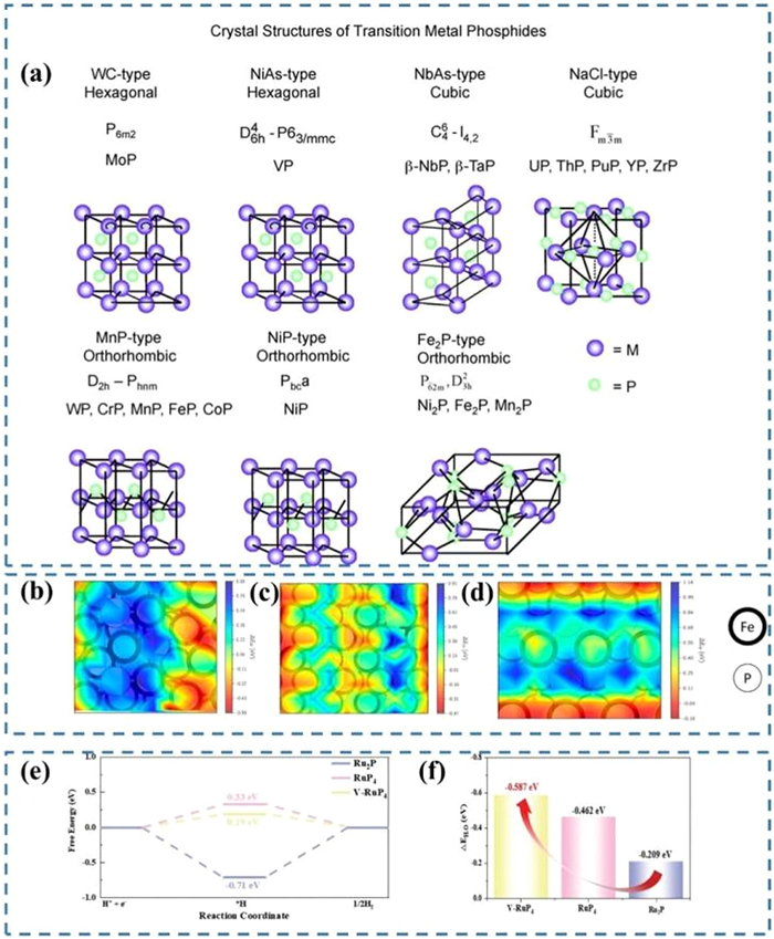
Unlike M-rich TMPs, P-rich TMPs (x: y ≤ 1:2) form layered, chain-like or 3D network frameworks through P-P bonds. These bonds promote electron sharing among P atoms and reduce their demand for electrons from metals. This mitigates electron deficiency at metal centers, which optimizes H adsorption strength. Concurrently, the weak and reactive P-P bonds contribute to high catalytic activity. In Figs. 2e and f, P-rich RuP4 gives ΔGH* (0.33 eV) and water adsorption energy (-0.462 eV) closer to the ideal values than M-rich Ru2P (ΔGH*: -0.71 eV; water adsorption energy: -0.209 eV) [54]. However, these conditions also put P-rich TMPs in metastable state. The weak bonding energy causes them to decompose easily into M-rich TMPs and elemental phosphorus under high temperature conditions. This substantially complicates the synthesis of P-rich TMPs. The high reactivity also drives operational oxidation or disproportionation during operation inducing structural collapse. Additionally, abundant P-P bonds lead to relatively low carrier mobility and electrical conductivity of P-rich TMPs.
There exists a class of equimolar TMPs (M: P = 1:1) that lie between M-rich and P-rich TMPs. Their structures feature neither P-P nor M-M bonds. They consist entirely of M-P covalent bonds. This unique bonding configuration confers significant advantages. First, equimolar TMPs present superior stability compared to P-rich TMPs. For instance, P-rich nanoclusters (e.g., CoPn) tend to aggregate under electron beam irradiation, whereas CoP bulk materials maintain structural integrity [55]. Second, this structural feature enables equimolar TMPs (e.g., CoP) to demonstrate ΔGH* values close to thermoneutral (-0.22 eV) in the hydrogen evolution reaction (HER). Compared to M-rich TMPs (e.g., Ru2P with ΔGH* =-0.71 eV), its energy barrier for H* desorption is significantly reduced. The structure gives relatively favorable stability (superior to P-rich TMPs) and moderate H* adsorption energy (weaker than M-rich TMPs). These make them practical candidate materials for HER. However, strong M-P covalent bonds restrict electron donation from P to adjacent metal sites. Therefore, metal sites demonstrate reduced efficiency in activating and cleaving O-H bonds within H2O molecules under alkaline conditions (Volmer kinetics). Moreover, isolated or distantly spaced metal sites hinder efficient diffusion and coupling of adsorbed hydrogen atoms between neighboring sites (Tafel step). In summary, M-rich TMPs are limited by strong H adsorption and inactivation due to P leaching. P-rich TMPs face stability challenges during synthesis and operation. And equimolar TMPs are the most promising monometallic TMPs for application because of their moderate H adsorption energies and outstanding stabilities. But they still require optimization of water dissociation kinetics in alkaline media.
Importantly, the inherent instability of TMPs often leads to dynamic phase reconstruction during electrocatalytic processes. For instance, M-rich TMPs undergo surface oxidation under anodic potentials to form metal hydroxides (M-OOH) or phosphates. While such reconstructed layers may enhance water dissociation kinetics, uncontrolled reconstruction accelerates phosphorus leaching and causes structural collapse. For example, Shi et al. observed that the yolk-shell CoP@FeCoP/NC polyhedra completely transformed their surface phosphides into metal oxides after anodic reactions with significant phosphorus loss [56]. Although this reconstructed surface exhibits enhanced catalytic activity, the phase transformation fundamentally destroys the catalyst framework. This phenomenon is particularly severe in monometallic TMPs due to their homogeneous composition and lack of stabilization mechanisms. Therefore, future catalyst designs must strike a balance between leveraging reconstruction-induced activity enhancement and suppressing its associated structural instability. This challenge requires advanced strategies to guide the reconstruction towards a beneficial path.
Monometallic TMPs possess inherent catalytic limitations due to their different stoichiometric ratios. Thus researchers have developed a series of strategies aimed at enhancing their catalytic abilities. These strategies mainly focus on morphology engineering, doping engineering and defect engineering. The following subsections detail these three strategies.
Morphology engineering optimizes the electronic structure and operational stability of TMPs by precisely regulating their microscopic geometric features. Taking Ni2P as an example, the high-curvature surfaces of zero-dimensional nanoparticles generate low-coordination Ni sites, which accelerate surface oxidative reconstruction during HER [57]. This process forms an active phase containing Ni-O/OH bonds. The reconstructed layer serves as the true active site maintaining reaction, while the pristine Ni2P primarily provides conductive support. Furthermore, small-sized nanoparticles effectively mitigate lattice strain, resulting in a bond length shrinkage rate of only 0.27% after HER (Fig. 3a). Therefore, Ni2P nanoparticles achieve a 10-h current density without attenuation at a high overpotential of -400 mV under the synergistic effect of high curvature surface and small size effect (Fig. 3b).
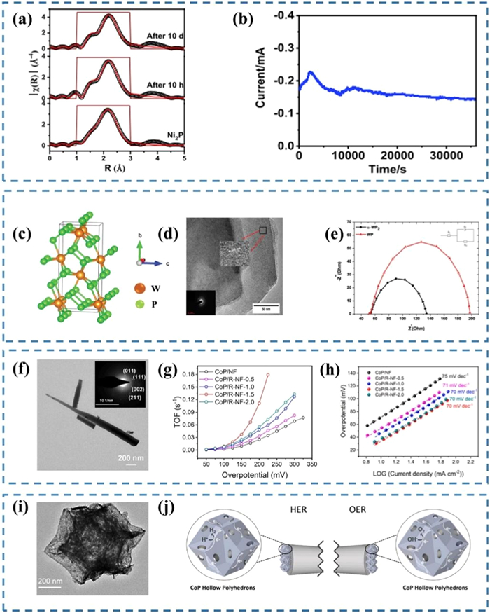
In addition, crystal structure is the foundation of TMPs' performance, which directly affects their intrinsic activity and macroscopic morphological features [58]. In TMPs, P atoms form tetrahedral coordination configurations with metal atoms through sp3 hybridization. This bonding characteristic profoundly influences the types of crystal structures (such as orthorhombic, cubic and hexagonal crystal systems) and the growth orientation of atomic layers [59]. For instance, Nkabinde et al. induced the formation of monoclinic α-WP2 by controlling precursor ratios (Fig. 3c) [60]. As a P-rich TMP, α-WP2 features phosphorus atoms arranged in a two-dimensional corrugated layer network. It grows preferentially on the (-201) plane to form a few-layer stacked nanosheet morphology. This specific growth mode increases the interplanar spacing along the stacking direction to 0.468 nm (Fig. 3d), significantly enhancing the height of interlayer transport channels. Consequently, the proton transport rate is substantially increased, resulting in a 41% reduction in charge transfer resistance compared to the WP electrode (α-WP2: 93.06 Ω; WP: 154.5 Ω, Fig. 3e).
The above mentioned zero-dimensional nanoparticles and two-dimensional nanosheets show their unique small-size effects and interlayer channel expansion ability during catalytic process, respectively. By contrast, the tip effect dominates in one-dimensional nanomaterials, particularly nanowires. Transmission electron microscopy (TEM) characterization (Fig. 3f) indicates that the tip radius of curvature of CoP nanowires is less than 10 nm [61]. This geometric feature causes localized charge accumulation and generates enhanced electric fields. These electric fields polarize adsorbed H2O directionally and enlarge O-H dipoles. This lowers the water dissociation barrier. Simultaneously, the continuous metal atomic chains within the nanowires establish efficient hydrogen spillover pathways, further lowering the H* migration barrier. This mechanism effectively addresses the kinetic limitation in the Tafel step caused by discontinuous active sites in equimolar TMPs. In terms of performance, the turnover frequency (TOF) of CoP nanowires is 4.48 times higher than that of bulk CoP (Fig. 3g), and its Tafel slope dropped by 30 mV/dec (Fig. 3h). These results confirm comprehensive optimization of water dissociation kinetics by the tip effect of the nanowires.
The essence of HER is the process of adsorption and desorption between protons/ions in the electrolyte and the active site on the catalyst surface. Thus a desirable catalyst often needs to be rich in active sites and be able to make sufficient contact with electrolyte. Three-dimensional nanostructures present unique advantages in this aspect. Among them, hollow structure occupies a rather important position. At present, their synthesis methods include the template method and the self-template method. The template approach employs a hard template (such as SiO2 nanospheres) or a soft template (such as bubbles) as a sacrifice template [62]. TMPs precursors are deposited onto these templates, and then the templates are removed by chemical etching or heat treatment. The self-template approach forms hollow structures by the self-assembly behavior of precursors during reaction process. It requires no additional template and is easy to operate. For example, Liu prepared a hollow polyhedral CoP taking an organic skeleton with Co as the central metal for a template (Fig. 3i) [63]. Its active sites are exposed on both the inner and outer surfaces, thereby significantly increasing specific surface area. Fig. 3j demonstrates the principle of promoting HER and OER occurrence on hollow CoP polyhedral. Abundant pores accelerate electrolyte penetration to achieve efficient catalysis. Moreover, the hollow structure with high mechanical strength reduces the volume change of catalyst during reaction. This makes it possible for catalyst to work for a long time at high current densities. Though morphology engineering enhances active site exposure and mass transport in monometallic TMPs, its ability to regulate the intrinsic electronic structure is limited. Thus, it is necessary to introduce heteroatoms for modulating electronic structure or to construct active sites through defect engineering. These represent essential strategies to overcome inherent limitations of monometallic TMPs.
Doping engineering is a strategy to introduce foreign atoms into the lattice of TMPs. Appropriate synergistic effects should exist between the dopant and the host atoms to produce a stronger catalytic effect than a single component [64]. The first thing to notice is the electronic effect between them. For cations dopants, they are often employed to directly replace transition metal atoms in TMPs. According to Sabatier's principle, the adsorption capacity of the catalyst should not be too strong or too weak for the reactants [65]. The ideal state of HER catalyst is achieved when ΔGH* is 0. In TMPs that show excessively strong (weak) hydrogen adsorption, ΔGH* can be tuned toward this thermoneutral value by carefully adding cations with higher (lower) electronegativity than the parent transition metal atoms. For example, Sun et al. introduced Fe ions to optimize Ni2P nanostructure [66]. The electronegativity of Fe atom is 1.83, which is lower than that of Ni atom (1.91). Fig. 4a shows that the Fe2-Ni2P/C sample possesses a slightly lower Ni oxidation state than the Ni2P/C sample. This is the result of partial electron loss. The reduced electron density adjusted the ΔGH* value of the Ni2P catalyst to near 0 (Fig. 4b). Fig. 4c also proves that the above operation significantly improves the HER ability of Ni2P catalyst.
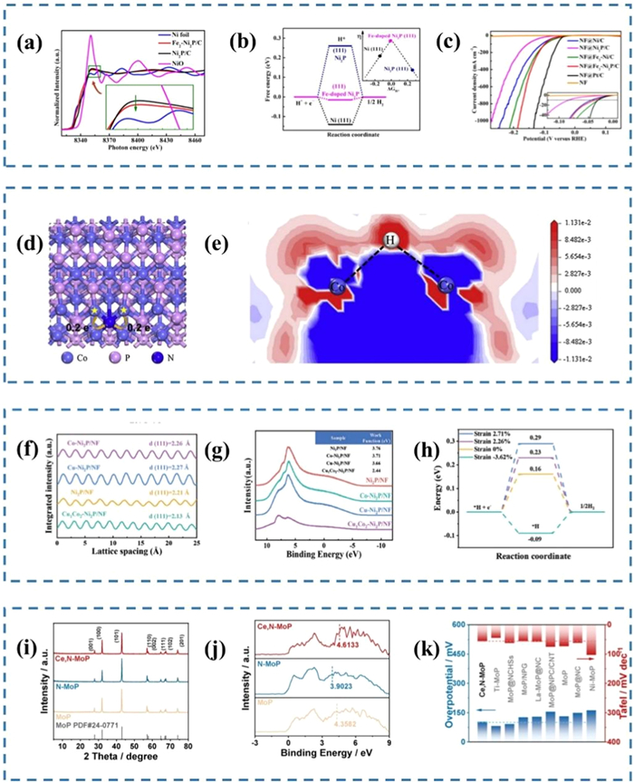
Unlike cations, anionic dopants replace P atoms in TMPs [67]. Men and colleagues replaced P atom with N ion that is far more electronegative than it [68]. Fig. 4d demonstrates that Co atoms transfer about 0.2 more electrons to N atoms than P atoms. The electron density difference (Fig. 4e) further proves that N doping weakens the interaction between Co and H. However, it should be noted that elements with too large electronegativity difference from the host atom should not be selected as dopants. Excessive electronegativity differences may lead to too much electron transfer thus causing lattice distortion or charge imbalance. This is very detrimental to the stability of catalysts. Synergies between atoms include geometrical effects in addition to electronic effects. Geometric effect refers to the lattice distortion, surface reconstruction and defect formation caused by the introduction of heteroatoms. These geometric effects cause electron redistribution and increase of active sites to some extent. Unfortunately, it also features the negative effects of stress accumulation and stability reduction. Therefore, it is necessary to balance the advantages and disadvantages of geometric effect by selecting size-matched dopant, controlling dopant concentration and optimizing synthesis approach.
Recent studies have further achieved synergistic optimization of both electronic structure and catalytic performance in TMPs through co-doping strategies. The co-doping is an approach of introducing two or more ions into the catalyst simultaneously. It exploits different characteristics of multiple dopants to optimize the catalyst. Compared to single ion doping, the co-doping allows more flexible regulation by selecting different dopant combinations as required [69,70]. Feng et al. employed a bimetallic Cu/Co co-doping strategy to modify Ni2P [71]. Ordinarily, the atomic radii of Cu and Co are both larger than that of Ni, which should have led to tensile strain. However, a significant electronegativity difference exists between Cu and Co. Cu tends to accept electrons from Ni2P, while Co tends to donate electrons to Ni2P. This establishes an electron transfer pathway of Cu ← Ni ← Co within the material. The redistribution of electrons enhances the covalency of the Ni-P bonds, resulting in bond shortening. While atomic size differences primarily cause local lattice distortions, electronic coupling can trigger global lattice reconstruction. Thus, electronic coupling between bimetals overcomes the stretching effect of single doping. It ultimately drives the lattice to reverse contract, causing the (111) crystal plane spacing to shrink from 2.21 Å to 2.13 Å (Fig. 4f). Correspondingly, its work function drops from 3.76 eV to 2.44 eV (Fig. 4g). This increases the density of states near the Fermi level and accelerates charge transfer. In addition, lattice compression precisely tunes ΔGH* to a near-thermal neutral value (Fig. 4h) through three mechanisms: Raising d-band center position, increasing metal-H orbital hybridization and optimizing surface atomic coordination environment. Meanwhile, Pu et al. developed a cationic/anion (Ce/N) co-doped MoP system [72]. Unlike stable Ni2P, MoP nanostructure is fragile and cannot withstand high strain. Therefore, this study selects N (0.70 Å) and Ce (2.70 Å) atoms as dopants due to their complementary sizes. This effectively avoids the lattice distortion of MoP nanostructure (Fig. 4i). This system establishes a Ce → Mo/P → N charge transfer channel through the electronic synergy (Fig. 4j). This channel not only upshifts the d-band center to enhance intermediates adsorption, but also reduces the *OH desorption energy barrier. This electronic synergy directly translates into a breakthrough in catalytic performance: Ce/N-MoP catalyst requires only 102.6 mV overpotential for alkaline HER at 10 mA/cm2 with a Tafel slope of 56.3 mV/dec (Fig. 4k). These cases demonstrate that co-doping triggers dual geometric-electronic effects to overcome limitations of mono-doping.
In conclusion, doping engineering is a mature and effective technique for improving TMPs performance. This strategy introduces heteroatoms to induce efficient electronic synergistic effects and lattice strain, which reduces catalytic reaction energy barriers. However, certain dopants can compromise host crystal stability. For instance, doping with atoms showing excessive electronegativity differences may trigger charge imbalance under high potentials, leading to lattice distortion or phase transformation/collapse. Additionally, precise control over doping concentration, distribution uniformity, and elemental valence states remains challenging in practical implementation. These represent critical bottlenecks in current doping engineering. Nevertheless, it remains one of the core technologies for boosting TMPs' catalytic performance. Therefore, future research should focus on atomic-level control of doping parameters and exploration of stability reinforcement mechanisms to collaboratively optimize catalyst activity and long-term stability.
Defect engineering is also a conventional technique to improve HER catalytic ability of TMPs. Defects are regions in the crystal structure that deviate from the ideal periodic arrangement [73]. Proper defect engineering generates abundant active sites, tailors electronic configurations and boosts electrical conductivity. Zhang et al. prepared MoP nanoparticles with various defects in situ by low temperature calcination [74]. Fig. 5a includes defects such as boundaries, holes, dislocations and distortions. XPS spectra (Fig. 5b) and ESR spectra (Fig. 5c) prove that these defects are oxygen-containing defects caused by oxygen atom doping. The abundance of defects and oxygen atoms provide the catalyst with sufficient active centers and favorable intrinsic conductivity, respectively.
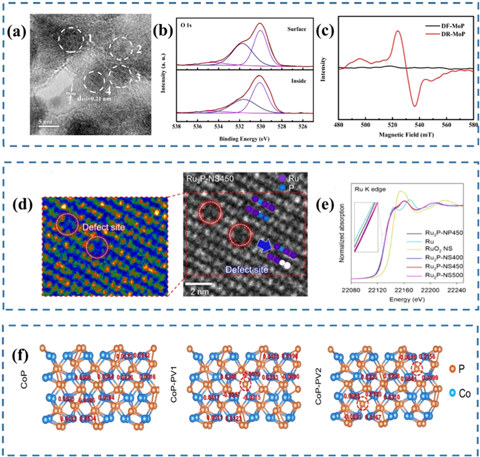
Beyond the aforementioned defects, vacancy defects represent another critical class for regulating the performance of TMPs. It is formed by removing parts of atoms, such as phosphorus atoms or metal atoms. The synthesis ways include high-temperature reduction, chemical etching, molten salt method and doping-induced method [75]. Jin induced RuO2 nanostructure into porous Ru2P nanostructure by phosphating process [76]. Some P atoms are removed and become phosphorus vacancies as shown in Fig. 5d. Phosphorus vacancies expose many Ru active sites for the catalyst. Many Ru atoms are missing in the edge region of porous structure leading to the formation of metal vacancies. These vacancy defects reduce the number of Ru-Ru metal bonds in porous Ru2P nanosheet, resulting in a higher Ru K edge energy than other samples (Fig. 5e). This means that the interaction of Ru atoms with the surrounding P atoms is enhanced. Li also confirmed that phosphorus vacancy contributes to electron transfer to Co site through Bader charge states (Fig. 5f) [77]. This action realigns the local charge distribution of CoP nanostructure.
Undeniably, the rich variety of defects tends to expose new active sites and optimize electronic structure for catalysts. This results in a significant impact on the reaction kinetics of HER. But some defects may destroy the crystal structure of samples [78]. For example, vacancy defects have the probability of causing corrosion or structural collapse of nanostructures at high potentials [79]. And it is difficult to accurately control the concentration and distribution of defects in actual preparation. These are the current obstacles encountered in defect engineering. However, it is still an effective technique to enhance the catalytic capacity of TMPs. Therefore, future research should focus on the precision and stability of defect modulation and the feasibility of large-scale preparation.
The essence of catalyst lowering HER energy barrier is to accelerate the completion of adsorption-desorption process by employing itself as a reaction site. Active site and hydrogen adsorption energy have a great influence on the difference of catalysts [80,81]. The intrinsic activity of m onometallic TMPs is inevitably limited by their single transition metal. Therefore, it is a general trend in HER field to introduce multiple elements to form multi-element compounds [82,83].
Multi-element transition metal phosphides (TMPs) are compounds consisting of two or more transition metal atoms and P atoms. The presence of multiple transition metals induces configurational complexity in compounds, manifesting as intricate crystal structures with heterogeneous coordination environments and orbital hybridization effects [84,85]. For example, Du et al. synthesized NiCoP catalyst with nested three-dimensional structures [86]. This unique structure greatly enhances the number of active sites and electron transport rate. And its catalytic ability also benefits from the synergistic effect between Ni and Co atoms. Ni and Co atoms possess 8 and 7 electrons in the 3d orbitals with corresponding electronic configurations of [Ar] 3d84s2 and [Ar] 3d74s2 [87]. Their 3d orbital electron numbers are close but different, and their electronic structures have partially filled d orbitals. This allows them to regulate the overall electronic structure and hydrogen adsorption energy of catalyst through electronic interactions. Moreover, their similar atomic radii facilitate lattice matching to form stable solid solutions or compounds [88,89]. The outstanding coordination between them supports that NiCoP catalyst is effectively used water electrolysis (Figs. 6a-c). Similarly, Fe atom is adjacent to Co atom on the periodic table. It also works synergistically with Ni atom. Liu and group designed an amorphous NiFeP nanomaterial [90]. Fig. 6d shows that this amorphous structure presents a state of long-range disorder and short-range order. This gives the nanomaterial a wide energy band and an abundance of unpaired electrons that contribute to its ΔGH* approaching 0 (Fig. 6e). Typically, multi-element TMPs give superior controllability than monometallic TMPs. During their synthesis, it is possible to accurately control their properties by adjusting ratio between different transition metals [91–93]. Li fabricated a low valence CoMoP catalyst by adjusting the ratio of Co and Mo elements [94]. The Co element optimizes the adsorption energy of the intermediates thereby promoting the generation of H2. On the other hand, Mo atoms enhance the adsorption and activation of reactants such as H+ or H2O. Two elements with complementary catalytic properties could effectively promote Volmer and Heyrovsky/Tafel steps.
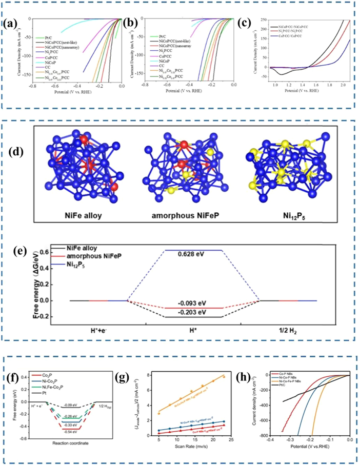
Significantly, ternary TMPs demonstrate stronger synergistic potential than binary systems. Li et al. constructed a porous phosphide compound that contains three transition metals (Ni, Co, and Fe) [87]. This catalyst achieves a performance leap through the collaborative efforts of the three elements. Ni element modulates the ΔGH* from strong adsorption region (-0.54 eV) to the ideal value (-0.33 eV) by weakening the Co-P bond and regulating the energy level position (Fig. 6f). Fe element induces the catalyst to present a porous morphology that boosts its electricdouble-layer capacitance to 267 mF/cm2 (Fig. 6g). This lays the foundation for the catalyst to react at high currents. Co element provides structural rigidity and high conductivity as the catalytic backbone. As shown in Fig. 6h, Ni-Co-Fe-P nanobricks (NBs) require only 190 mV overpotential to drive 800 mA/cm2. Although the ternary system is currently facing the challenge of elemental segregation, its "electronic-structure-stability" marks an important leap in TMPs design towards high-dimensional component space. Overall, the effect of multiple matched atoms working together to improve catalytic ability is significant. And many new catalysts are developed by combining different kinds of transition metals. This makes ternary TMPs have specific advantages and broad application prospects.
Multi-element transition metal phosphorus based compounds are a class of compounds with rich physicochemical properties. Their chemical formula, MPX, integrates a transition metal (M), phosphorus (P), and a non-metallic element (X = S, Se, Te) [95]. The introduction of non-metallic elements allows the compound to form a unique layered structure. The FePS3 nanostructure synthesized by Tang is a multilayer network composed of FeS6 and P2S6 polyhedrons (Fig. 7a) [96]. The multilayer structure provides abundant active sites for catalyst. These sites offer ideal binding sites for subsequent Ni atom anchoring. Fig. 7b confirms that the configuration of Ni atoms replacing P atoms in P2S6 polyhedron is outstanding. Its formation energy is low, so it is thermodynamically stable [97]. And it also significantly increases the hydrogen adsorption and dissociation capacity of electrode.
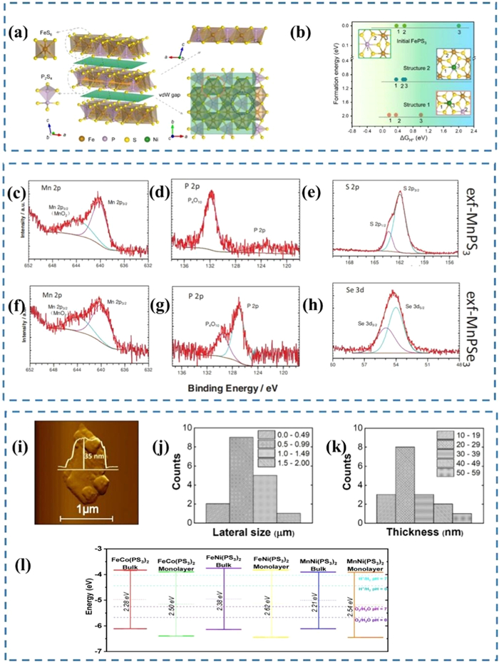
The interlayer interactions in ternary transition metal phosphorus based compounds are stabilized through van der Waals bonding, so they tend to be anisotropic and easy to peel [98,99]. They can be peeled into single or multilayer nanosheets by approaches such as shear force peeling [100,101]. MnPX3 (X = S, Se) catalysts show notable size reduction and interlayer dissociation properties after being stripped [102]. This operation allows them to present HER enhancement in both acidic and alkaline media. During the stripping process, the surface of sample is exposed to the external environment and inevitably undergoes partial oxidation. Figs. 7c-h demonstrate the oxidation of Mn and P atoms in samples. Notably, MnPSe3 presents lower oxidation levels than MnPS3. This originates from the larger atomic radius of Se compared to S. The diffuse 4p orbital energy levels of Se atom weaken the nucleophilic attack ability of oxygen atoms on the material surface. It endows MnPSe3 with a higher oxidation potential. Moreover, the lower electronegativity of the Se atom also effectively reduces the electron cloud density of the [P2Se6]4- unit, thereby inhibiting the oxidation of the P atom. The oxide overlayers impede H* adsorption. Furthermore, insulating oxides substantially increase charge transfer resistance. Therefore, preference should be given to materials with high oxidation resistance during designing catalysts (such as MnPSe3). Additionally, for oxidation-sensitive materials, processing should be conducted under an inert atmosphere with optimized exfoliation protocols to minimize oxidation.
A recent study synthesizes FeCoP2S6 bimetallic phosphosulfide crystals via chemical vapor transport method [103]. This study employs the microwave-ultrasonic co-deposition technique to process FeCoP2S6 to obtain ultrathin nanosheets (exf-FeCoP2S6). Atomic force microscopy (AFM) characterization reveals that the exfoliated product presents a regular two-dimensional lamellar structure (Fig. 7i). Its transverse dimensions and thicknesses concentrated in the 0.5–0.99 μm range and 20–29 nm range, respectively (Figs. 7j and k). This demonstrates that the microwave-ultrasonic synergistic technology effectively dissociates layered structures while preventing over-fragmentation and crystal damage. The highly uniform nanosheet sample provides an ideal platform for precisely exploring dimensional effect. DFT calculations further reveal the Fe/Co bimetallic synergy mechanism (Fig. 7l). FeCoP2S6 possesses a more stable electronic ground state and an optimized band structure compared to other bimetallic systems. The band alignment of FeCoP2S6 shows a conduction band minimum (CBM) at -0.81 V vs. RHE and valence band maximum (VBM) at 1.83 V vs. RHE. These values are closer to the thermodynamic potentials for HER (0 V) and OER (1.23 V) than FeNiP2S6 (CBM: -0.75 V, VBM: 1.87 V) and MnNiP2S6 (CBM: -0.73 V, VBM: 1.91 V). This optimized band structure facilitates more efficient charge transfer during electrocatalysis. Such innovation establishes a design paradigm for new layered energy materials through full-chain control from atomic combinations to microstructural regulation.
While TMPs demonstrate favorable HER competence, their composite derivatives enhance performance through interfacial engineering. Composite structure increases the intrinsic activity of catalysts in a variety of ways, such as providing fast electron transport channels, changing the arrangement of atoms at interface. It is expected that TMPs composite structure becomes the core of HER catalyst by understanding its working mechanism and exploring various composite structure combinations [104–106].
The practical applications of TMPs still face problems such as poor electrical conductivity and insufficient exposure of active sites. This challenge finds potential resolution in carbon hybridization strategies. Carbon materials usually feature high specific surface area and electrical conductivity. There are various types of carbon materials, mainly including reduced graphene oxide (rGO), carbon nanotubes (CNTs) and carbon cloth (CC). Their porous structures enable them to regulate the size of the product and provide fast channel for electron transport. For example, rGO effectively improves the charge transport efficiency of TMPs due to its high electron mobility and tunable layered structure. Xu et al. constructed a porous Ni2P/rGO composite via a polystyrene microsphere template method [107]. The introduction of rGO suppresses the agglomeration of Ni2P nanoparticles and accelerates electron transfer. This enables the catalyst to achieve a low HER overpotential of 21.4 mV (at 10 mA/cm2) and 28 h continuous stability in alkaline environments. It is significantly outperforming single-component materials. On the other hand, CNTs provide unique protection and activation mechanisms for TMPs through confinement effects. Wang et al. encapsulated Ni2P/MoP composite nanoparticles within N, P-codoped CNTs cavities (Ni2P/MoP@CNTs-CC) [108]. The distorted π-bonds in CNTs induce strong electronic interactions between TMPs and carbon walls, reducing the kinetic barrier for H* adsorption. Their narrow cavities inhibit the aggregation of active particles while simultaneously permitting electrolyte infiltration. This "cage-reactant" mechanism makes the electrode with industrial-grade stability (> 100 h at 50 mA/cm2). Additionally, carbon cloth (CC) is often preferred as a catalyst substrate due to its outstanding mechanical strength and stability to enhance overall stability. Zha synthesized P-defect rich Ni-doped CoP3 supported by N-doped carbon nanofibers (NCFs) on CC (p-NiCoP/NCFs@CC) [109]. NCFs provide a wide growth space for samples. They avoid close packing of p-NiCoP nanoparticles. This makes the p-NiCoP/NCFs@CC catalyst present lower overpotential (Figs. 8a and b) and faster reaction kinetics (Fig. 8c) than the p-NiCoP@CC catalyst. All three types of carbon materials (rGO, CNTs, and CC) optimize the catalytic behavior of TMPs through similar electronic modulation mechanisms. DFT calculations (Figs. 8d and e) demonstrate that charge transfer from the carbon matrix to TMPs effectively regulates the ΔGH*, representing the pivotal mechanism for performance enhancement.
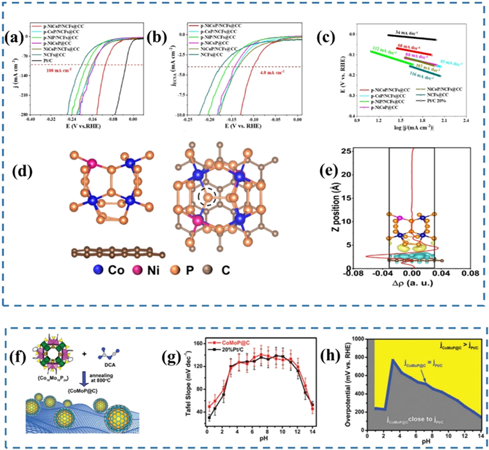
The above examples mention doping carbon materials with N element. N atom is more electronegative than C atom. Therefore, N doping effectively increases carrier concentration and accelerates electron transport. Meanwhile, it also introduces oxygen-containing functional groups and nitrogen-containing functional groups to increase the hydrophilicity of carbon materials. Suitable hydrophilicity facilitates electrolyte penetration and proton transport on catalyst surface [110]. These advantages allow N-doped carbon materials to be outstanding electrocatalysts. It is further corroborated by Ma et al., who engineered a CoMoP core encapsulated in N-doped carbon shell (CoMoP@NC, Fig. 8f) [111]. The HER performance of CoMoP core is significantly enhanced by the strong proton adsorption capacity of the outer shell. Its catalytic activity is close to that of the Pt/C electrode (Fig. 8g). Remarkably, Fig. 8h shows CoMoP@C catalyst outperforms Pt/C at high current densities. This is attributed to the stable carbon shell, which effectively inhibits the oxidation and corrosion of the TMP nucleus under harsh conditions. The synergy between carbon matrices and TMPs yields electrocatalysts that simultaneously achieve high efficiency and long-term stability.
In conclusion, TMPs has achieved significant improvements in terms of electrical conductivity, reaction kinetics and stability by combining with carbon materials. The carbon matrix offers superior conductive network and high specific surface area. Its structural and chemical properties synergistically optimize the processes of electron transport, electrolyte wetting and proton adsorption. It is evident that the carbon hybridization strategy possesses great potential in constructing efficient and stable HER electrocatalysts. Nevertheless, future research still needs to focus on the precise regulation of the composite interface structure, the development of large-scale controllable preparation processes, and the in-depth understanding of the performance degradation mechanism under extreme working conditions. Such advancements are prerequisites to accelerate the application process of TMPs/C composite catalysts.
Combining TMPs with other TMPs is also a research hotspot in heterostructures. This approach merges advantages of distinct TMPs [112,113]. The performance enhancement in TMP/TMP heterostructures primarily stems from three key mechanisms: Bifunctional synergistic catalysis, interfacial charge transfer, and enhanced structural stability. The first mechanism is bifunctional synergistic catalysis. Typically, a judiciously selected combination of TMPs enables complementary advantages for different catalytic steps at the atomic scale. For instance, Huang's group synthesized CoP/CoMoP heterostructures via hydrothermal-impregnation followed by low-temperature phosphidation method [114]. In alkaline environment, the CoMoP interface sites excel at accelerating the Volmer step, with a significantly lower H2O dissociation energy barrier (0.56 eV) compared to CoP (0.84 eV). Conversely, the CoP interface sites favor promoting H* adsorption/desorption (Heyrovsky/Tafel steps), giving a ΔGH* (-0.37 eV) closer to the ideal value (0 eV) than that of CoMoP (-0.72 eV). These two types of active sites are closely adjacent at the heterointerface, allowing rapid transfer of the H* intermediate (Fig. 9a). This synergistic effect at the atomic scale overcomes the kinetic limitations of single material in specific reaction steps. And it is key to its alkaline HER performance (η10 = 34 mV, η100 = 94 mV), which approaches that of commercial Pt/C electrode (η10 = 33 mV, η100 = 99 mV) (Fig. 9b).
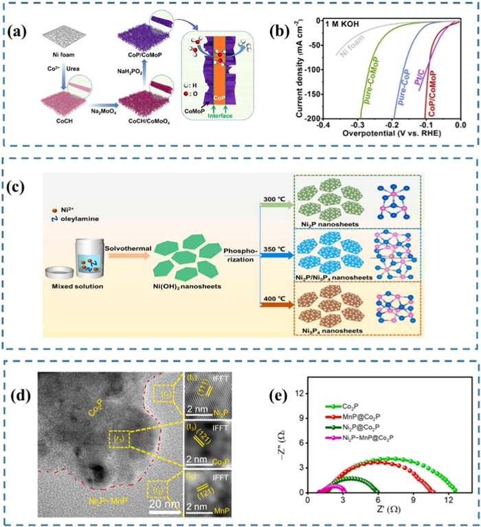
The second mechanism is interfacial charge transfer. When two TMPs with different electronic properties come into contact, interfacial charge transfer occurs between them. To achieve Fermi level equilibration, electrons spontaneously flow from the material with the lower work function to the one with the higher work function. This process creates a space charge region at the interface, generating a directional built-in electric field. This field promotes charge separation and transport. During electrocatalysis, it efficiently drives the separation of charge carriers (electrons and holes) at the interface, thereby accelerating interfacial charge transfer kinetics. Furthermore, interfacial charge transfer significantly alters the local electron density and density of states distribution near the interface atoms. For example, the Ni2P/Ni5P4 mixed phase can be precisely synthesized by controlling the calcination temperature (Fig. 9c) [115]. They are both n-type semiconductors and possess different work functions (Ni2P: 3.69 eV; Ni5P4: 3.86 eV) and Fermi levels. The significant work function difference drives electrons transfer from Ni2P to Ni5P4, forming a built-in electric field. This field results in a much lower Rct for Ni2P/Ni5P4 (2.76 Ω) in 1 mol/L KOH compared to the single-phase Ni2P (20.69 Ω) and Ni5P4 (32.26 Ω). Its Tafel slope (75.1 mV/dec) is also markedly lower than those of the single phases (109.9 mV/dec and 94.0 mV/dec, respectively). DFT calculations further confirm that the ΔGH* at the Ni2P/Ni5P4 interface sites (-0.113 eV) is closer to the ideal value (0 eV) than that of Ni2P (-0.398 eV) or Ni5P4 (-0.202 eV). It can be seen that the interface optimization has significantly enhanced the intrinsic activity of the catalyst.
TMP/TMP heterostructures also incorporate core-shell architectures, where one material fully encapsulates another [116]. Electrocatalytic efficiency is decided by strategic selection of core and shell components. The main roles of the core include providing support and facilitating charge transport. Therefore, it is usually chosen for TMPs (such as M-rich TMPs) with mechanical stability and high electrical conductivity. The shell material is directly exposed to the electrolyte to participate in the catalytic reaction. And it needs to protect the core material from the corrosion of electrolyte to improve the chemical stability and durability of the core-shell structure. Care should be taken to select TMPs with high catalytic activity and chemical stability as shells. Kandel et al. recently reported a unique hierarchical core-shell catalyst (Ni2P-MnP@Co2P) [117]. Microstructural characterization clearly reveals Co2P nanoflowers (shell) intimately coupled onto Ni2P-MnP nanosheets (core) (Fig. 9d). This unique core-shell nanostructure delivers multifunctional advantages.The Ni2P-MnP nanosheet serves as a conductive substrate, providing efficient charge transfer efficiency for the catalyst (Fig. 9e). The Co2P nanoflower expands surface area and accelerates bubble detachment via hydrophobic surfaces. It simultaneously maximizes active site exposure and corrosion resistance. Ni2P-MnP@Co2P offers an extremely low overpotential of 60 mV at 10 mA/cm2 thanks to these advantages.
The TMP/TMP heterostructures boost electrocatalytic performance through functional complementarity of components and electronic regulation at the interface. In particular, the core-shell configuration achieves HER activity close to that of commercial platinum carbon. However, its large-scale application is still limited by bottlenecks such as the loss of electronic coupling efficiency and the phase transition deactivation. Future research needs to rely on in-situ interface characterization to analyze the charge migration path and develop adaptive protective shells to suppress corrosion phase transitions.
The field of TMP heterostructures has achieved systematic theoretical and experimental advancement. Numerous materials can combine with TMPs to form composite structures. Transition metals themselves may serve as composite layers. Like other materials, they provide multilevel architectures for catalysts. Sun's Ni(Cu)@NiFeP/NM electrode demonstrates a triple-layered structure (Figs. 10a and b) [118]. The Ni(Cu) alloy nanotube framework supports a mesoporous NiFeP layer, significantly expanding the electrochemical active surface area. This hierarchical structure effectively promotes the diffusion of reactants and the desorption efficiency of product gases (such as H2 or O2), thereby enhancing the overall reaction kinetics. Notably, most TMPs offer semiconducting properties. At TM/TMP heterojunctions, electron transfer stabilizes as the Fermi levels equilibrate across the interface, forming a space-charge region with pronounced band bending. This redistribution of interfacial electrons creates a Schottky barrier, known as the Mott-Schottky effect. The resulting electric field accelerates electron transfer while reducing charge-transfer resistance (Fig. 10c). These synergistic mechanisms collectively empower TM/TMP catalysts with exceptional catalytic performance.
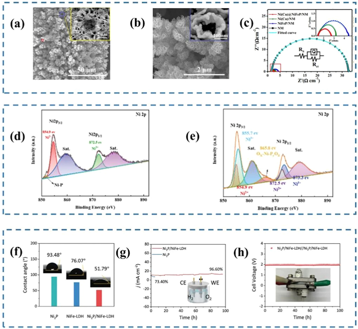
Transition metal oxides (TMOs) represent another key type of material for constructing TMP heterostructures due to their abundant oxidation states and exceptional chemical stability [119]. As illustrated in Figs. 10d and e, NiO@NiP/NF sample (containing Ni3+) shows more complex nickel speciation compared to Ni2P/NF (Ni2+) [120]. Multivalent nickel ions participate in proton adsorption and reduction processes to enhance HER efficiency. Simultaneously, the chemically inert NiO component protects the NiP structure from alkaline electrolyte corrosion while preventing phosphorus leaching. Furthermore, some rigid-framework TMOs (e.g., TiO2, NiO) mitigate active particle fragmentation and component dissolution during long-term cycling [121]. This assists in enhancing the structural stability of the catalyst. However, attention needs to be paid to the intrinsic expansion properties and electrical conductivity of TMOs. These potential negative impacts can be avoided through reasonable heterostructure design (such as introducing highly conductive substrates or combining them with conductive materials).
Transition metal hydroxides (TMHs) constitute another important class of composite materials [122]. Their layered structure and abundant hydroxyl groups confer high specific surface area and excellent hydrophilicity. For instance, Ge and colleagues integrated NiFe-LDH with Ni2P [123]. The NiFe-LDH possesses a large number of hydroxyl groups (-OH) and interlayer water molecules, which ensures superb surface wettability (Fig. 10f). This hydrophilic surface promotes electrolyte penetration and exposes numerous active sites. However, TMHs typically suffer from poor conductivity. Conductive Ni2P (or other TMPs) effectively mitigates this deficiency by providing efficient charge-transfer pathways. Moreover, the flexible layered structure of TMH accommodates volume changes during long-term electrochemical operation, preserving the structural integrity of TMPs [124]. This synergy extends the catalyst's operational lifetime by nearly tenfold (Fig. 10g). Additionally, TMHs (particularly LDHs) feature ionic sieving effects within interlayer channels. They preferentially facilitate the transmission of water molecules (H2O) and hydroxide ions (OH-), while effectively blocking ions with strong corrosive properties such as Cl-. It significantly enhances corrosion resistance of Ni2P sample in seawater electrolysis (Fig. 10h). The above advantages of TMHs offer strong synergy with the high catalytic activity and favorable electrical conductivity of TMPs. This greatly expands the potential of TMHs/TMPs catalysts for applicability in harsh environments like seawater electrolysis.
TMPs enhance their catalytic activity of HER by constructing heterostructures with transition metals (TM), oxides (TMOs), and hydroxides (TMHs). However, this field still faces core challenges such as the difficulty in precisely regulating heterogeneous interfaces, the ambiguity of dynamic reaction mechanisms, the insufficiency of long-term stability under harsh working conditions, and the laboratory-industrialization gap. In the future, efforts should be focused on atomic-level precise synthesis (in-situ reconstruction technology), working condition oriented design (seawater electrolysis adaptation) and multi-scale mechanism analysis (in-situ characterization and simulation combination). Moreover, it is necessary to promote large-scale device integration to break through performance and lifespan bottlenecks. The ultimate goal is to achieve the large-scale application of TMP heterogeneous structure catalysts in green hydrogen industry.
As summarized in Table 1, this review systematically summarizes recent advancements in TMPs for HER, and reveals their structure-property relationships and performance optimization pathways through multi-scale design strategies. Based on proton-coupled electron transfer theory, we dissect kinetic differences in HER between acidic and alkaline media, while establishing a multi-parameter evaluation framework. Subsequent sections discuss TMPs' catalytic mechanisms: (1) Monometallic TMPs are limited by strong hydrogen adsorption energy and P loss. They achieve breakthrough from three strategies of form regulation, doping and defect engineering. (2) Multi-element TMPs leverage synergistic interactions to optimize electronic structures and catalytic activity, yet face challenges such as elemental segregation and structural instability during synthesis/operation. These limitations are mitigated through atomic-level design, controlled exfoliation techniques and precise stoichiometric tuning of transition metal ratios. (3) Composite architectures establish rapid charge channels, induce built-in electric fields and suppress phosphorus leaching for TMPs.

 DownLoad:
CSV
DownLoad:
CSV
| Type of catalyst | Catalyst | Overpotential | Tafel slope (mV/dec) | Electrolyte | Ref. |
| Monometallic TMPs | α-WP2 | 271 mV@10 mA/cm2 | 86.83 | 0.5 mol/L H2SO4 | [60] |
| CoP/R-NF | 35 mV@10 mA/cm2 | 70 | 1.0 mol/L KOH | [61] | |
| NF@Fe2−Ni2P/C | 39 mV@10 mA/cm2 | 30 | 1.0 mol/L KOH | [66] | |
| N-CoP/CC | 39 mV@10 mA/cm2 | 58 | 1.0 mol/L KOH | [68] | |
| Cu1Co2-Ni2P/NF | 51 mV@10 mA/cm2 | 52.3 | 1.0 mol/L KOH | [71] | |
| Ce, N-MoP | 102.6 mV@10 mA/cm2 | 56,3 | 1.0 mol/L KOH | [72] | |
| DR-MoP | 104 mV@10 mA/cm2 | 50 | 1.0 mol/L KOH | [74] | |
| Ru2P-NS450 | 26 mV@10 mA/cm2 | 31 | 1.0 mol/L KOH | [76] | |
| Multi-element TMPs | NiCoP/CC | 62 mV@10 mA/cm2 | 68.2 | 1.0 mol/L KOH | [86] |
| FeCoP2S6 | 409 mV@10 mA/cm2 | 72 | 1.0 mol/L KOH | [103] | |
| exf-FeCoP2S6 | 329 mV@10 mA/cm2 | 58 | 1.0 mol/L KOH | [103] | |
| Composite structure of TMPs | p-NiCoP/NCFs@CC | 107 mV@100 mA/cm2 | 68 | 1.0 mol/L KOH | [109] |
| CoP/CoMoP | 34 mV@10 mA/cm2 | 33 | 1.0 mol/L KOH | [114] | |
| Ni2P/Ni5P4 | 62 mV@10 mA/cm2 | 75.1 | 1.0 mol/L KOH | [115] | |
| Ni2P−MnP@Co2P | 60 mV@10 mA/cm2 | 43.3 | 1.0 mol/L KOH | [117] | |
| Ni(Cu)@NiFeP/NM | 33 mV@10 mA/cm2 | 56.6 | 1.0 mol/L KOH | [118] | |
| NiO@NiP/NF | 76 mV@10 mA/cm2 | 98 | 1.0 mol/L KOH | [120] | |
| Ni2P/NiFe-LDH | 230 mV@100 mA/cm2 | 47.43 | 1.0 mol/L KOH | [123] |
However, these above performance optimizations are mostly limited to the laboratory environment, and practical industrial applications still face challenges. Fig. 11 illustrates potential bottlenecks and possible applications for TMPs in the future. Firstly, it is still unclear what the reaction mechanism of HER in alkaline electrolytes. Current understanding lacks understanding of the H2O dissociation and hydrogen adsorption/desorption processes. The second is the question of long-term stability. TMPs suffer from progressive phosphorus leaching and structural collapse during long-term operation. These conditions are especially prominent at high current density, which seriously affects the operational life and economy viability of catalysts. The third point is the challenge of catalysts large-scale synthesis. Existing synthesis methods (e.g., hydrothermal) show poor reproducibility and energy inefficiency, which are incompatible with industrial-scale production. TMPs still needs to be further studied and explored in the aspects of mechanism research, structural design and industrial production.
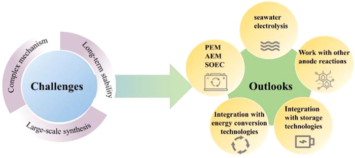
The development of catalysts for TMPs will also need to focus on the following aspects as research into HER technology intensifies. Seawater electrolysis is a rather developed direction. Abundant seawater resources provide HER with sufficient raw materials. But it demands catalysts with dual chloride corrosion resistance. In addition, HER is possible in many different electrolytes. Different electrolytes will result in different anode reactions. A key energy-efficiency enhancement strategy involves replacing the sluggish anodic OER with more readily oxidizable small molecules (e.g., alcohols, urea, hydrazine). These small-molecule oxidation reactions (e.g., methanol oxidation reaction (MOR) at 0.14 V, urea oxidation reaction (UOR) at 0.37 V, hydrazine oxidation reaction (HzOR) at -0.33 V) show significantly reduced thermodynamic barriers and faster reaction kinetics than OER with high theoretical potential (1.23 V vs. RHE) and slow four-electron transfer kinetics. This substitution can lower the overall electrolysis voltage by 300–500 mV (e.g., Ni2P/MoO2/NF requires only 1.35 V@10 mA/cm2 in urea-assisted electrolysis) [125]. Furthermore, the tunable electronic structure of TMPs catalysts promotes small-molecule dehydrogenation/oxidation by weakening N-H or C-H bonds (e.g., N2H4 dehydrogenation in HzOR). Crucially, this strategy transforms the energy-consuming OER process into value-creating pathways-such as formic acid production via MOR, urea-containing wastewater degradation via UOR, and non-toxic treatment of hydrazine pollutants via HzOR. This strategy not only reduces energy consumption but also enhances economic efficiency.
Moreover, TMPs catalysts have achieved significant breakthroughs in industrial applications of anion exchange membrane (AEM) and proton exchange membrane (PEM) electrolyzers. Studies demonstrate that various TMPs-based catalysts enable efficient hydrogen production at industrial-grade current densities (> 500 mA/cm2), with performance enhancement stemming from synergistic optimization between device design and catalyst properties. AEM electrolyzers utilize binder-free catalyst-coated membrane (CCM) technology to directly construct catalytic layers on the membrane surface. This eliminates the shielding and degradation risks of traditional binders to active sites. PEM electrolyzers employ low-ohmic-resistance proton-conducting membranes and precision membrane electrode assemblies to optimize charge transfer and gas-liquid separation efficiency under high current densities. Within these systems, TMPs catalysts (e.g., sulfur-doped CoP in PEM) present enhanced bonding strength (elevated Co-P bond energy) and optimized hydrogen adsorption energy, enabling stable operation at 500 mA/cm2 for over 140 h under a cell voltage of 1.70 V [126]. In summary, TMPs catalysts fully adapt to the challenging operating conditions of AEM/PEM devices thanks to their high intrinsic conductivity, adjustable electronic structure and composited-enhanced stability. These devices serve as a crucial link connecting the high-performance capabilities of the laboratory with industrial applications. And in the future, complete energy systems could be formed by integrating HER with other energy conversion and storage technologies (fuel cells, metal-air batteries, etc.). These systems will help reduce the cost of water electrolysis and improve energy efficiency. In conclusion, future research should focus on interdisciplinary cooperation, combining theoretical calculation, experimental research and engineering application.
The authors declare that they have no known competing financial interests or personal relationships that could have appeared to influence the work reported in this paper.
Xingyu Liu: Writing – original draft, Visualization, Validation, Software, Methodology, Investigation, Formal analysis, Data curation, Conceptualization. Xiang Wu: Writing – review & editing, Validation, Resources, Project administration, Methodology, Investigation, Funding acquisition, Formal analysis, Data curation, Conceptualization.
The authors declare no conflict of interests.
The work is supported by National Natural Science Foundation of China (No. 52472227).
D. Liu, G.Y. Xu, H. Yang, et al., Adv. Funct. Mater. 33 (2023) 202208358.
Y. Chen, Y.D. Liu, L. Li, et al., Adv. Funct. Mater. 34 (2024) 202401452.
D.P. Zhao, R. Zhang, M.Z. Dai, et al., Small 18 (2022) 2107268. doi: 10.1002/smll.202107268
A. Kazemi, F. Manteghi, Z. Tehrani, ACS Omega 9 (2024) 7310–7335.
S.Y. Pan, C. Li, T.T. Xiong, et al., App. Catal. B: Environ. 341 (2024) 123275. doi: 10.1016/j.apcatb.2023.123275
X.Y. Liu, H. Pang, X. Wu, Chin. Chem. Lett. 37 (2026) 111479. doi: 10.1016/j.cclet.2025.111479
W. Ma, X.Y. Zhang, W.Y. Li, et al., Nanoscale 15 (2023) 11759–11776. doi: 10.1039/D3NR01940C
C.L. Qin, S. Chen, H. Gomaa, et al., Acta Phys. Chim. Sin. 40 (2024) 2307059. doi: 10.3866/PKU.WHXB202307059
M. Hermesmann, T.E. Müller, Prog. Energy Combust. Sci. 90 (2022) 100996. doi: 10.1016/j.pecs.2022.100996
M. Wappler, D. Unguder, X. Lu, et al., Int. J. Hydrog. Energy 47 (2022) 33551–33570. doi: 10.1016/j.ijhydene.2022.07.253
G. Squadrito, G. Maggio, A. Nicita, Renew. Energy 216 (2023) 119041. doi: 10.1016/j.renene.2023.119041
K. Wang, J.H. Zhou, M.Z. Sun, et al., Adv. Mater. 35 (2023) 2300980. doi: 10.1002/adma.202300980
Y.H. Liu, J. Ding, F.H. Li, et al., Adv. Mater. 35 (2023) 2207114. doi: 10.1002/adma.202207114
X.Y. Liu, M.D. Wang, A. Umar, et al., Dalton Trans. 52 (2023) 10457–10464. doi: 10.1039/D3DT01732J
A. Goyal, S. Louisia, P. Moerland, et al., J. Am. Chem. Soc. 146 (2024) 7305–7312. doi: 10.1021/jacs.3c11866
X.H. Zhang, A.P. Wu, D.X. Wang, et al., App. Catal. B: Environ. 328 (2023) 122474. doi: 10.1016/j.apcatb.2023.122474
P. Liu, J.A. Rodriguez, T. Asakura, et al., J. Phys. Chem. B 109 (2005) 4575–4583.
Y.M. Hu, W.C. Li, L. Li, et al., Appl. Catal. A: Gen. 662 (2023) 119267. doi: 10.1016/j.apcata.2023.119267
L.L. Qi, Z.Y. Huang, M. Liao, et al., Chem. Eur. J. 29 (2023) 2301521.
W.J. Liu, W.X. Liu, T. Hou, et al., Nano Res. 17 (2024) 4797–4806. doi: 10.1007/s12274-024-6433-8
L.L. Zhang, Z.P. Wang, J.T. Zhang, et al., Nano Res. 16 (2023) 6552–6559. doi: 10.1007/s12274-022-5322-2
C. Feng, M.Y. Lv, J.X. Shao, et al., Adv. Mater. 35 (2023) 2305598. doi: 10.1002/adma.202305598
L.L. Ji, Y.J. Wei, P.R. Wu, et al., Chem. Mater. 33 (2021) 9165–9173. doi: 10.1021/acs.chemmater.1c02609
L. Ji, H.F. Zheng, Y.J. Wei, et al., Sci. China Mater. 65 (2022) 431–441. doi: 10.1007/s40843-021-1743-7
F.P. Chen, B.H. Zhao, M.Y. Sun, et al., Nano Res. 15 (2022) 10134–10141. doi: 10.1007/s12274-022-4489-x
Y. Liu, X. Li, Q.H. Zhang, et al., Angew. Chem. Int. Ed. 59 (2020) 1718–1726. doi: 10.1002/anie.201913910
A. Goyal, M.T.M. Koper, Angew. Chem. Int. Ed. 60 (2021) 13452–13462. doi: 10.1002/anie.202102803
W.F. Zhai, Y.Y. Ma, D. Chen, et al., InfoMat 4 (2022) e12357. doi: 10.1002/inf2.12357
S.L. Jiao, X.W. Fu, S.Y. Wang, et al., Energy Environ. Sci. 14 (2021) 1722–1770. doi: 10.1039/D0EE03635H
X.L. Jiang, H.S. Jang, S.G. Liu, et al., Angew. Chem. Int. Ed. 60 (2021) 4110–4116. doi: 10.1002/anie.202014411
H.K. Bu, F.J. Guo, Y. Zhao, et al., J. Phys. Chem. C 127 (2023) 1808–1821. doi: 10.1021/acs.jpcc.2c07199
H. Ding, C.J. Su, J.B. Wu, et al., J. Am. Chem. Soc. 146 (2024) 7858–7867. doi: 10.1021/jacs.4c01379
L. Shi, J.D. Chen, S.L. Zhao, et al., Chem Catal. 3 (2023) 100734.
R.T. Liu, Z.L. Xu, F.M. Li, et al., Chem. Soc. Rev. 52 (2023) 5652–5683. doi: 10.1039/D2CS00681B
C. Wei, Y.M. Sun, G.G. Scherer, et al., J. Am. Chem. Soc. 142 (2020) 7765–7775. doi: 10.1021/jacs.9b12005
X.Y. Liu, W.C. Zhang, X. Wu, et al., Energy Mater. Adv. 6 (2025) 160. doi: 10.34133/energymatadv.0160
M.T.M. Koper, J. Electroanal. Chem. 660 (2011) 254–260. doi: 10.1016/j.jelechem.2010.10.004
S. Sebbahi, A. Assila, A. Alaoui Belghiti, et al., Int. J. Hydrogen Energy 82 (2024) 583–599. doi: 10.1016/j.ijhydene.2024.07.428
O. Van Der Heijden, S. Park, R.E. Vos, et al., ACS Energy Lett. 9 (2024) 1871–1879. doi: 10.1021/acsenergylett.4c00266
P. Sharma, D. Mukherjee, S. Sarkar, et al., Green Chem. 24 (2022) 5535–5546. doi: 10.1039/D2GC00801G
H. Chen, Y.S. Zhou, W. Guo, et al., Chin. Chem. Lett. 33 (2022) 1831–1840. doi: 10.1016/j.cclet.2021.09.034
J.C. Wilson, S. Caratzoulas, D.G. Vlachos, et al., Nat. Commun. 14 (2023) 2384. doi: 10.1038/s41467-023-37935-6
M.A. Qadeer, X.X. Zhang, M.A. Farid, et al., J. Power Sources 613 (2024) 234856. doi: 10.1016/j.jpowsour.2024.234856
J.M. Ge, D.B. Zhang, Y. Qin, et al., App. Catal. B: Environ. 298 (2021) 120557. doi: 10.1016/j.apcatb.2021.120557
B.W. Wang, X.X. Chen, Y.J. He, et al., App. Catal. B: Environ. 346 (2024) 123741. doi: 10.1016/j.apcatb.2024.123741
P.M. Bodhankar, P.B. Sarawade, P. Kumar, et al., Small 18 (2022) 2107572. doi: 10.1002/smll.202107572
Z.Y. Yu, Y. Duan, X.Y. Feng, et al., Adv. Mater. 33 (2021) 2007100. doi: 10.1002/adma.202007100
Z.X. Yan, Z.R. Liu, G.S. Zhou, et al., Angew. Chem. Int. Ed. 64 (2025) 202501964. doi: 10.1002/anie.202501964
C.A. Downes, K.M. Van Allsburg, S.A. Tacey, et al., Chem. Mater. 34 (2022) 6255–6267. doi: 10.1021/acs.chemmater.2c00085
R. Anne Acedera, A. Theresse Dumlao, D. Donn Matienzo, et al., J. Energy Chem. 89 (2024) 646–669. doi: 10.1016/j.jechem.2023.10.044
S.M. El-Refaei, P.A. Russo, N. Pinna, ACS Appl. Mater. Inter. 13 (2021) 22077–22097. doi: 10.1021/acsami.1c02129
S.T. Oyama, T. Gott, H.Y. Zhao, et al., Catal. Today 143 (2009) 94–107. doi: 10.1016/j.cattod.2008.09.019
D.E. Schipper, Z.H. Zhao, H. Thirumalai, et al., Chem. Mater. 30 (2018) 3588–3598. doi: 10.1021/acs.chemmater.8b01624
J. Liu, J.H. Ren, Y.M. Du, et al., Adv. Funct. Mater. 34 (2024) 202315773.
H.P. Wang, C. Zhang, D.L. Zhang, et al., Small 20 (2024) 202403170.
J.H. Shi, F. Qiu, W.B. Yuan, et al., Chem. Eng. J. 403 (2021) 126312. doi: 10.1016/j.cej.2020.126312
S. Madadkhani, S. Nandy, K.H. Chae, et al., ACS Appl. Energy Mater. 7 (2024) 3157–3165. doi: 10.1021/acsaem.3c03145
C.S. Wang, Q. Zhang, B. Yan, et al., Nano-Micro Lett. 15 (2023) 52. doi: 10.1007/s40820-023-01024-6
M.X. Du, D. Li, S.Z. Frank Liu, et al., Chin. Chem. Lett. 34 (2023) 108156. doi: 10.1016/j.cclet.2023.108156
S.S. Nkabinde, P.V. Mwonga, S. Mpelane, et al., New J. Chem. 45 (2021) 15594–15606. doi: 10.1039/D1NJ00927C
R.J. Zhou, J.H. Zhang, J.X. Long, et al., J. Colloid Interface Sci. 683 (2025) 509–520. doi: 10.1016/j.jcis.2024.12.046
H. Jiang, M.Z. Sun, S.L. Wu, et al., Adv. Funct. Mater. 31 (2021) 2104951. doi: 10.1002/adfm.202104951
M.J. Liu, J.H. Li, ACS Appl. Mater. Inter. 8 (2016) 2158–2165. doi: 10.1021/acsami.5b10727
D.K. Wang, X.Y. Huai, A. Abdukader, et al., Appl. Surf. Sci. 660 (2024) 159972. doi: 10.1016/j.apsusc.2024.159972
Z. Chen, Z.Y. Liu, X. Xu, Nat. Commun. 14 (2023) 2512. doi: 10.1038/s41467-023-38307-w
H. Sun, Y.X. Min, W.J. Yang, et al., ACS Catal. 9 (2019) 8882–8892. doi: 10.1021/acscatal.9b02264
X. Sun, S.X. Song, G.J. Yan, et al., Dalton Trans. 53 (2024) 8843–8849. doi: 10.1039/D4DT00615A
Y.N. Men, P. Li, F.L. Yang, et al., App. Catal. B: Environ. 253 (2019) 21–27. doi: 10.1016/j.apcatb.2019.04.038
L.K. Putri, B. -J. Ng, R.Y.Z. Yeo, et al., Chem. Eng. J. 461 (2023) 141845. doi: 10.1016/j.cej.2023.141845
M.T. Chen, J.J. Duan, J.J. Feng, et al., J. Colloid Interface Sci. 605 (2022) 888–896. doi: 10.1016/j.jcis.2021.07.101
C. Feng, M.Y. Lv, J.X. Shao, et al., Adv. Mater. 35 (2023) 2305598. doi: 10.1002/adma.202305598
Y. Pu, M.Y. Li, Y.M. Liao, et al., Chem. Select 10 (2025) e202405928.
S.S. Li, J.R. Sun, J.Q. Guan, Chin. J. Catal. 42 (2021) 511–556. doi: 10.1016/S1872-2067(20)63693-2
X.Y. Zhang, Z.Z. Wu, D.Z. Wang, Electrochim. Acta 281 (2018) 540–548. doi: 10.1016/j.electacta.2018.05.176
L.W. Xiong, Y.F. Qiu, X. Peng, et al., Nano Energy 104 (2022) 107882. doi: 10.1016/j.nanoen.2022.107882
X.Y. Jin, H. Jang, N. Jarulertwathana, et al., ACS Nano 16 (2022) 16452–16461. doi: 10.1021/acsnano.2c05691
Z.D. Li, C.Y. Zhang, Y. Yang, et al., Inorg. Chem. Front. 10 (2023) 325–334. doi: 10.1039/D2QI01902G
C.G. Lang, Y.T. Xu, X.D. Yao, Chin. J. Catal. 64 (2024) 4–31. doi: 10.1016/S1872-2067(24)60105-1
H. Su, X.D. Pan, S.Q. Li, et al., Carbon Energy 5 (2023) e296. doi: 10.1002/cey2.296
J.Y. Li, J. Hu, M.K. Zhang, et al., Nat. Commun. 12 (2021) 3502. doi: 10.1038/s41467-021-23750-4
B.R. Guo, J.Y. Zhao, Y. Xu, et al., ACS Appl. Mater. Inter. 16 (2024) 8939–8948. doi: 10.1021/acsami.3c19077
B.B. Yang, D. Bin, Q.M. Zhong, et al., J. Colloid Interface Sci. 602 (2021) 222–231. doi: 10.1016/j.jcis.2021.06.009
Z.P. Yu, Y.F. Li, V. Martin-Diaconescu, et al., Adv. Funct. Mater. 32 (2022) 2206138. doi: 10.1002/adfm.202206138
K.K. Mandari, N. Son, S. Pandey, et al., Int. J. Hydrogen Energy 48 (2023) 17000–17013. doi: 10.1016/j.ijhydene.2023.01.237
S.K. Tang, X. Wu, Y. Bando, Energy Fuels 38 (2024) 23083–23090. doi: 10.1021/acs.energyfuels.4c04534
C. Du, L. Yang, F.L. Yang, et al., ACS Catal. 7 (2017) 4131–4137. doi: 10.1021/acscatal.7b00662
A. Li, L. Zhang, F.Z. Wang, et al., App. Catal. B: Environ. 310 (2022) 121353. doi: 10.1016/j.apcatb.2022.121353
Y.M. Hu, T.T. Chao, Y.P. Li, et al., Angew. Chem. Int. Ed. 62 (2023) e202308800. doi: 10.1002/anie.202308800
S.K. Tang, D. Li, X. Wu, CrystEngComm 27 (2025) 5319–5326. doi: 10.1039/D5CE00608B
J.Y. Liu, X. Liu, H. Shi, et al., App. Catal. B: Environ. 302 (2022) 120862. doi: 10.1016/j.apcatb.2021.120862
M.R. Kandel, U.N. Pan, P.P. Dhakal, et al., Small 20 (2024) 2307241. doi: 10.1002/smll.202307241
D. Bandyopadhyay, S. Ghosh, L. Houben, et al., ACS Appl. Energy Mater. 6 (2023) 10987–10995. doi: 10.1021/acsaem.3c01761
B.B. Yang, Q.Y. Zhao, Y.Y. Du, et al., Colloids. Surface. A 671 (2023) 131663. doi: 10.1016/j.colsurfa.2023.131663
W.P. Li, G. Cheng, S.M. Peng, et al., Chem. Eng. J. 430 (2022) 132699. doi: 10.1016/j.cej.2021.132699
F.M. Oliveira, J. Paštika, I. Plutnarová, et al., Small Methods 7 (2023) 2201358. doi: 10.1002/smtd.202201358
C.Y. Tang, D. He, N. Zhang, et al., Energy Environ. Mater. 5 (2022) 899–905. doi: 10.1002/eem2.12205
L. Wang, T. Maxisch, G. Ceder, Chem. Mater. 19 (2007) 543–552. doi: 10.1021/cm0620943
Z.S. Li, Y. Yue, J.C. Peng, et al., Chin. Chem. Lett. 34 (2023) 107119. doi: 10.1016/j.cclet.2022.01.012
S.J. Zhao, Y. Chen, Y.D. Liu, et al., Green Chem. 25 (2023) 6170–6187. doi: 10.1039/D3GC01806G
K. Pramoda, C.N.R. Rao, J. Mater. Chem. A 11 (2023) 16933–16962. doi: 10.1039/D3TA01629C
J. Wang, X.Z. Li, B. Wei, et al., Adv Funct. Mater. 30 (2020) 1908708. doi: 10.1002/adfm.201908708
R. Gusmão, Z. Sofer, M. Pumera, Adv Funct. Mater. 29 (2019) 1805975. doi: 10.1002/adfm.201805975
F.M. Oliveira, J. Paštika, I. Ayaz, et al., Mater. Today Energy 39 (2024) 101468. doi: 10.1016/j.mtener.2023.101468
J.T. Zhang, Z. Zhang, Y.F. Ji, et al., App. Catal. B: Environ. 282 (2021) 119609. doi: 10.1016/j.apcatb.2020.119609
X.R. Zhang, C.Y. Sun, S.S. Xu, et al., Nano Res. 15 (2022) 8897–8907. doi: 10.1007/s12274-022-4771-y
D.D. Ren, Z.Z. Liang, Y.H. Ng, et al., Chem. Eng. J. 390 (2020) 124496. doi: 10.1016/j.cej.2020.124496
Q. Xu, S.Q. Huang, Y.G. Lv, et al., Mater. Res. Bull. 139 (2025) 113657.
J.J. Wang, R.Q. Guo, W.X. Zhu, et al., J. Alloys Compd. 968 (2023) 171948. doi: 10.1016/j.jallcom.2023.171948
D.W. Zha, R.X. Wang, S.J. Tian, et al., Nano-Micro Lett. 16 (2024) 250. doi: 10.1007/s40820-024-01471-9
C. Cui, R.F. Cheng, H. Zhang, et al., Adv Funct. Mater. 30 (2020) 2000693. doi: 10.1002/adfm.202000693
Y.Y. Ma, C.X. Wu, X.J. Feng, et al., Energy Environ. Sci. 10 (2017) 788–798. doi: 10.1039/C6EE03768B
Z.X. Duan, D.P. Zhao, Y.C. Sun, et al., Nano Res. 15 (2022) 8865–8871. doi: 10.1007/s12274-022-4673-z
Y.X. Gao, Z. Chen, Y. Zhao, et al., App. Catal. B: Environ. 303 (2022) 120879. doi: 10.1016/j.apcatb.2021.120879
X. Huang, X. Xu, X. Luan, et al., Nano Energy 68 (2020) 104332. doi: 10.1016/j.nanoen.2019.104332
C.J. Lyu, C.Y. Cao, J.R. Cheng, et al., Chem. Eng. J. 464 (2023) 142538. doi: 10.1016/j.cej.2023.142538
W.Z. Yuan, T.F. Jiang, X.Q. Fang, et al., Chem. Eng. J. 439 (2022) 135743. doi: 10.1016/j.cej.2022.135743
M.R. Kandel, U.N. Pan, P.P. Dhakal, et al., App. Catal. B: Environ. 331 (2023) 122680. doi: 10.1016/j.apcatb.2023.122680
Q.Q. Sun, M. Zhou, Y.Q. Shen, et al., J. Catal. 373 (2019) 180–189. doi: 10.1016/j.jcat.2019.03.039
L.L. Qiao, A.Q. Zhu, D. Liu, et al., Chem. Eng. J. 454 (2023) 140380. doi: 10.1016/j.cej.2022.140380
C.Y. Sun, H. Wang, J.W. Ren, et al., Nanoscale 13 (2021) 13703–13708. doi: 10.1039/D1NR03567C
Z.B. Liang, W.Y. Zhou, S. Gao, et al., Small 16 (2020) 1905075. doi: 10.1002/smll.201905075
D.P. Zhao, X.Y. Liu, W.C. Zhang, et al., Small Methods 8 (2024) 2301474. doi: 10.1002/smtd.202301474
Z.Q. Ge, J.W. Li, H.J. Zhang, et al., Adv Funct. Mater. 34 (2024) 2411024. doi: 10.1002/adfm.202411024
M.D. Wang, X.Y. Liu, X. Wu, Nano Energy 114 (2023) 108681. doi: 10.1016/j.nanoen.2023.108681
M. Yang, Y.M. Jiang, M.J. Qu, App. Catal. B: Environ. 269 (2020) 118803. doi: 10.1016/j.apcatb.2020.118803
S.Q. Zhang, S.K. Ma, Z.H. Wang, Fuel 397 (2025) 135436. doi: 10.1016/j.fuel.2025.135436

Figure 2 (a) Crystal structures of metal transition phosphides. Reproduced with permission [52]. Copyright 2009, Elsevier B.V. (b-d) Contours of H binding strength on the surfaces of Fe3P (100), Fe2P (100) and FePFe-t (011). Reproduced with permission [53]. Copyright 2018, American Chemical Society. (e) The calculated desorption free energy of hydrogen on Ru site of different models. (f) Water adsorption energy on the Ru site of different models. Reproduced with permission [54]. Copyright 2024, Wiley-VCH GmbH.

Figure 3 (a) Ni K-edge EXAFS signal in k-space of Ni2P, Ni2P after 10 h, and Ni2P after 10 d compounds. (b) Chronoamperometry of Ni2P under -400 mV for 10 h. Reproduced with permission [57]. Copyright 2024, American Chemical Society. (c) Tungsten diphosphide (α-WP2, monoclinic) nanoparticles. (d) HRTEM image of α-WP2. (e) Nyquist plots of WP and α-WP2 catalysts. Reproduced with permission [60]. Copyright 2021, Royal Society of Chemistry. (f) TEM image of CoP nanowires. (g) TOF values of the as-obtained electrodes. (h) The corresponding Tafel plots. Reproduced with permission [61]. Copyright 2025, Elsevier Inc. (i) TEM image of CoP hollow polyhedron. (j) Schematic diagram to illustrate the HER and OER catalytic principles on CoP hollow polyhedron. Reproduced with permission [63]. Copyright 2016, American Chemical Society.

Figure 4 (a) Ni K-edge XANES spectra of Fe2−Ni2P/C, Ni2P/C, Ni foil, and NiO. (b) Gibbs free energies of absorbed hydrogen atom (ΔGH*) for HER. (c) HER polarization curves [66]. Copyright 2019, American Chemical Society. (d) The schematic of the electron transfers from Co to N after the substitution of N for P for CoP (210) surface. (e) The electron density difference of Co-H bonding region between the H adsorbed N-CoP (210) surface and the H adsorbed pristine CoP (210) surface. Reproduced with permission [68]. Copyright 2019, Elsevier B.V. (f) Integrated pixel intensities of pristine and strained Ni 2P along the Ni 2P (111) spacing direction. (g) UPS spectra of Ni2P/NF, Co–Ni2P/NF, Cu–NiP/NF, and Cu1Co2–Ni2P/NF. (h) ΔGH* diagram for Ni2P/NF, Cu1Co2–Ni2P/NF, Co–Ni2P/NF, and Cu–Ni2P/NF with 0%, −3.62%, +2.26%, and +2.71% strains, respectively. Reproduced with permission [71]. Copyright 2023, Wiley-VCH GmbH. (i) XRD patterns. (j) The valence band spectra (VBS) of MoP, N-MoP and Ce, N-MoP. (k) the comparison of overpotential and Tafel slope of Ce, N-MoP with some recently reported advanced MoP-based catalysts. Reproduced with permission [72]. Copyright 2025, Wiley-VCH GmbH.

Figure 5 (a) HRTEM image of DR-MoP (defect-rich MoP). (b) P 2p (c) ESR measurements of DR-MoP and DF-MoP (defect-free MoP). Reproduced with permission [74]. Copyright 2018, Pergamon-Elsevier Science Ltd. (d) High-resolution TEM image. (e) EXAFS fitting data. Reproduced with permission [76]. Copyright 2022, American Chemical Society. (f) Bader charge states of CoP, CoP-PV1, and CoP-PV2. Reproduced with permission [77]. Copyright 2022, Royal Society of Chemistry.

Figure 6 (a, b) LSV curves of HER in 0.5 mol/L H2SO4 and 1.0 mol/L KOH solution. (c) LSV curves using nest-like NiCoP/CC||NiCoP/CC, Ni2P/CC||Ni2P/CC, CoP/CC||CoP/CC as two electrodes in 1 mol/L KOH. Reproduced with permission [86]. Copyright 2017, American Chemical Society. (d) HER calculation models of NiFe alloy without phosphorus atom doping (NiFe alloy), amorphous NiFe doped with phosphorus atoms (amorphous NiFeP) and crystalline Ni12P5. (e) HER calculation results of NiFe alloy, amorphous NiFeP and Ni12P5. Reproduced with permission [90]. Copyright 2022, Elsevier B.V. (f) The corresponding free energy diagram for HER on Co2P, Ni doped Co2P, Ni, Fe co-doped Co2P and Pt. (g) The corresponding double-layer capacitances for HER. (h) Polarization curves of Co-P NBs, Ni-Co-P NBs, Ni-Co-Fe-P NBs and 40% Pt/C electrodes for HER. Reproduced with permission [87]. Copyright 2022, Elsevier B.V.

Figure 7 (a) Crystal structure of FePS3. (b) Energy diagram of Ni-FePS3 and FePS3 from first principles calculations. Reproduced with permission [96]. Copyright 2022, Wiley. (c-e) High-resolution XPS spectrum and peaks deconvolution of exf-MnPS3: Mn 2p, P 2p and S 2p. (f-h) High-resolution XPS spectrum and peaks deconvolution of exf-MnPSe3: Mn 2p, P 2p and Se 3d Reproduced with permission [102]. Copyright 2019, Wiley-VCH Verlag GmbH. (i) AFM image of exf-FeCoP2S6. (j) Statistical analysis of lateral size of exf-FeCoP2S6. (k) Statistical analysis of thickness of exf-FeCoP2S6. (l) Frontier band edges, CBM and VBM, and standard potentials for H+/H2 and O2/H2O at 0 and 7 pH. Reproduced with permission [103]. Copyright 2023, Elsevier Ltd.

Figure 8 (a) Polarization curves. (b) ECSA-normalized polarization curves. (c) Tafel curves for the HER. (d) Side and top views of NiCoP(200)def/Gr. (e) Charge differential analysis of NiCoP(200)def/Gr. Reproduced with permission [109]. Copyright 2024, Shanghai Jiao Tong Univ Press. (f) Illustration of the preparation of the CoMoP@C catalyst. (g) The variation of Tafel slopes of CoMoP@C and 20% Pt/C catalysts with the pH values (0–14). (h) The relationship between the overpotential, pH and current density of CoMoP@C and 20% Pt/C catalysts. Reproduced with permission [111]. Copyright 2017, Royal Society of Chemistry.

Figure 9 (a) The schematic diagram to illustrate the fabrication process of CoP/CoMoP via topotactic conversion from CoCH. (b) The HER iR-corrected polarization curves. Reproduced with permission [114]. Copyright 2020, Elsevier. (c) Schematic illustration of controllable phosphorization to prepare Ni2P/Ni5P4 nanosheets, Ni2P nanosheets and Ni5P4 nanosheets. Reproduced with permission [115]. Copyright 2023, Elsevier. (d) HRTEM image of Ni2P–MnP@Co2P. (e) Nyquist plot for EIS measurements of various materials. Reproduced with permission [117]. Copyright 2023, Elsevier.

Figure 10 (a, b) Ni(Cu)@NiFeP/NM (b, magnified image from the red square inserted in a). (c) Nyquist plots. Reproduced with permission [118]. Copyright 2019, Elsevier. (d) The deconvoluted high-resolution Ni 2p XPS spectra of Ni2P/NF. (e) The deconvoluted high-resolution Ni 2p of NiO@NiP/NF [120]. Copyright 2021, Royal Society of Chemistry. (f) Contact angle images. (g) Current–time curve. (h) Potential–time curve of Ni2P/NiFe-LDH tested at 100 mA/cm2 for overall seawater splitting. Reproduced with permission [123]. Copyright 2024, Wiley-VCH GmbH.
Table 1. Comparison of typical TMPs-based electrocatalysts.
| Type of catalyst | Catalyst | Overpotential | Tafel slope (mV/dec) | Electrolyte | Ref. |
| Monometallic TMPs | α-WP2 | 271 mV@10 mA/cm2 | 86.83 | 0.5 mol/L H2SO4 | [60] |
| CoP/R-NF | 35 mV@10 mA/cm2 | 70 | 1.0 mol/L KOH | [61] | |
| NF@Fe2−Ni2P/C | 39 mV@10 mA/cm2 | 30 | 1.0 mol/L KOH | [66] | |
| N-CoP/CC | 39 mV@10 mA/cm2 | 58 | 1.0 mol/L KOH | [68] | |
| Cu1Co2-Ni2P/NF | 51 mV@10 mA/cm2 | 52.3 | 1.0 mol/L KOH | [71] | |
| Ce, N-MoP | 102.6 mV@10 mA/cm2 | 56,3 | 1.0 mol/L KOH | [72] | |
| DR-MoP | 104 mV@10 mA/cm2 | 50 | 1.0 mol/L KOH | [74] | |
| Ru2P-NS450 | 26 mV@10 mA/cm2 | 31 | 1.0 mol/L KOH | [76] | |
| Multi-element TMPs | NiCoP/CC | 62 mV@10 mA/cm2 | 68.2 | 1.0 mol/L KOH | [86] |
| FeCoP2S6 | 409 mV@10 mA/cm2 | 72 | 1.0 mol/L KOH | [103] | |
| exf-FeCoP2S6 | 329 mV@10 mA/cm2 | 58 | 1.0 mol/L KOH | [103] | |
| Composite structure of TMPs | p-NiCoP/NCFs@CC | 107 mV@100 mA/cm2 | 68 | 1.0 mol/L KOH | [109] |
| CoP/CoMoP | 34 mV@10 mA/cm2 | 33 | 1.0 mol/L KOH | [114] | |
| Ni2P/Ni5P4 | 62 mV@10 mA/cm2 | 75.1 | 1.0 mol/L KOH | [115] | |
| Ni2P−MnP@Co2P | 60 mV@10 mA/cm2 | 43.3 | 1.0 mol/L KOH | [117] | |
| Ni(Cu)@NiFeP/NM | 33 mV@10 mA/cm2 | 56.6 | 1.0 mol/L KOH | [118] | |
| NiO@NiP/NF | 76 mV@10 mA/cm2 | 98 | 1.0 mol/L KOH | [120] | |
| Ni2P/NiFe-LDH | 230 mV@100 mA/cm2 | 47.43 | 1.0 mol/L KOH | [123] |
 下载: 导出CSV

 扫一扫看文章


扫一扫关注我们


 下载:
下载: