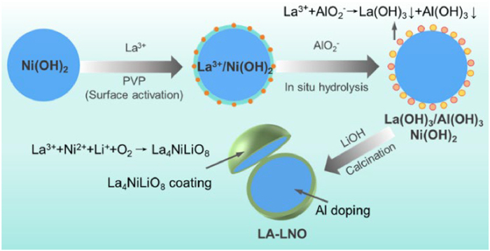
Figure 1.
Schematic diagram of the synthesis process of LA-LNO.

Enhancing cycling stability of high-nickel cobalt-free LiNiO2 through La/Al synergistic modification: A one-step synthesis approach
Doudou Bao , Jinwei Zhou , Ayaz , Li Wang , Xiangming He , Ziang Jiang , Feixiang Wu


As the electric vehicles (EVs) sector continues to mushroom [1], the demand for high-capacity battery materials is set to soar. LiFePO4 (LFP) and LiNi1 - x - yCoxMnyO2 (NCM) are common cathode materials in power batteries, valued for safety and high energy density, respectively. As consumers seek EVs with longer range, there is a growing focus on high-energy NCM materials. Yet, cobalt in NCM is expensive and raises ethical and supply chain concerns, given 74% of global reserves are from the Democratic Republic of Congo [2]. Nickel is more economical, and its increased presence in cathode materials can bolster energy density. As a result, there is a burgeoning interest in the development of high-nickel cobalt-free materials [3-6]. Despite their promise, these materials are often plagued by intrinsic flaws such as subpar cycle stability, mechanical fragility, and inadequate thermal robustness [7-10]. LiNiO2 (LNO), as the prototype material of high-nickel cobalt-free material, boasts the highest energy density among similar compounds. However, the defects of LNO are also the most prominent.
To overcome these hurdles, a plethora of modification studies have been undertaken on LNO, with the majority concentrating on single-modification techniques such as bulk doping [11-15], or surface coating [16,17]. In recent times, scholars have ventured into dual-modification strategies that integrate both bulk doping and surface coating. For example, Li et al. [18] discovered that the combination of Nb-doping with Nb2O5 coating improved the cycling stability of LNO. Similarly, Shen et al. [19] employed PO43− doping alongside Li3PO4 coating for dual modification, yielding a material with enhanced structural integrity and rate capability. Additionally, the combination of Ti doping with La4NiLiO8 coating has already been explored [20]. However, this approach was found to be ineffective in optimizing primary particles. Later, the same research group turned to B doping for NCM modification [21], though the H3BO3 employed is relatively costly. Regrettably, despite these strides, most dual-modification synthesis methodologies are intricate, involving multi-step procedures that present challenges for commercial scalability [22].
By contrast, prior work has demonstrated that Al doping can refine grain size [23-25]. Additionally, since double hydrolysis reactions are a form of coprecipitation, and AlO2− is a well-known species that readily undergoes double hydrolysis to form Al(OH)3 precipitates. Furthermore, the introduction of a La4NiLiO8 coating layer can augment the electronic conductivity of the cathode surface, diminish interfacial side reactions, and prevent microcracks formation [26]. Besides, La4NiLiO8 is an A2BO4-type layered perovskite material and a fast Li+ conductor along the crystallographic c-axis, composed of alternating perovskite layers (ABO3) and rock-salt layers (AO) [27]. Leveraging these insights, we introduce a synergistic modification strategy that combines Al doping with La4NiLiO8 coating. In this investigation, taking into account the ionic radii of La3+ (1.18 Å) and Al3+ (0.54 Å), we have developed a one-step synthesis technique that achieves both bulk Al doping and a surface epitaxial La4NiLiO8 coating for LNO, termed LA-LNO. Fig. 1 delineates the synthesis mechanism of LA-LNO. During the calcination process, the smaller Al3+ ions are integrated into the bulk structure, while the larger La3+ ions, due to their size and reactivity, form a La4NiLiO8 coating layer on the surface [20]. The outcomes reveal that the synergistic modification markedly boosts the cycling performance and rate capability of LNO, presenting a promising route for advancing high-nickel, cobalt-free cathode materials.
LA-LNO is fabricated via a one-step process involving an in situ reaction (Fig. S1 in Supporting information). This reaction yielded Ni(OH)2 coated with La(OH)3 and Al(OH)3, which is subsequently dried and calcined with LiOH at high temperatures to produce LA-LNO. Scanning electron microscopy (SEM) images of the precursors and the surface distribution of various elements on the Ni(OH)2 precursor displayed in Fig. S2 (Supporting information). These observations confirm the precipitation reaction induced on the surface of Ni(OH)2 successfully leads to the formation of the coated precursor.
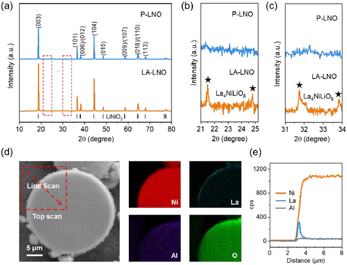
For the calcined samples, X-ray diffraction (XRD) patterns confirm that LA-LNO adopts the R-3m phase of LNO (PDF #04-007-9490) (Fig. 2a), indicating that the structure of the synergistically modified material remains intact. The integrity of the layered structure is evaluated using the I(003)/I(104) ratio, where a higher value signifies a more ideal layered structure with reduced Li+/Ni2+ disorder [28,29]. The I(003)/I(104) ratios for pristine LNO (P-LNO) and LA-LNO are 1.31 and 1.47, respectively, suggesting that the modification effectively enhances the layered structure and diminishes Li+/Ni2+ disorder. This conclusion is bolstered by Rietveld refinement results (Fig. S3, Tables S3 and S4 in Supporting information) and the Al doping level obtained from inductively coupled plasma (ICP) analysis (Table S2 in Supporting information). Additionally, the c-axis lattice parameter increases from 14.201 Å in P-LNO to 14.235 Å in LA-LNO. The XRD pattern of LA-LNO exhibits new diffraction peaks at 21.5°, 24.8°, 31.7°, and 33.8° (Figs. 2b and c), characteristic of the La4NiLiO8 phase [20]. This confirms the successful formation of the La4NiLiO8 coating layer on the surface of LA-LNO. Moreover, the (104) peak of LA-LNO shifts to the right compared to P-LNO, further validating the incorporation of Al into the bulk [30]. SEM images of the synthesized samples (Figs. S4a-f in Supporting information) show that the primary particles in LA-LNO are smaller and more densely packed, forming tighter secondary particles. Energy-dispersive spectroscopy (EDS) mapping of LA-LNO (Figs. S4g-l in Supporting information) reveal the distribution of element La Ni O Al on the surface of particles, indicating the successful synthesis of LA-LNO preliminarily. To further substantiate the synergistic modification of bulk Al doping and surface La4NiLiO8 epitaxial coating in LA-LNO, cross-sectional EDS analysis is conducted (Fig. 2d). The analysis shows that La is confined to the surface layer, while Al is uniformly distributed throughout the particle, with no surface enrichment, which is consistent with Line scanning (Fig. 2e). These findings definitively demonstrate that the synthesis method effectively accomplishes the desired synergistic modification. Transmission electron microscopy (TEM) images of P-LNO indicate that, compared with P-LNO, there are crystal structures with different orientations on the surface of LA-LNO, which is considered to be La4NiLiO8 (Fig. S5 in Supporting information), indicating successful surface optimization [31].
The elemental composition and oxidation states of the surface regions of P-LNO and LA-LNO are examined using X-ray photoelectron spectroscopy (XPS), focusing on the La 3d, O 1s, and Ni 2p orbitals (Fig. S6 in Supporting information), which indicates that the modification fosters the transition from Ni2+ to Ni3+. This reduction in Ni2+ content is beneficial, as it lessens the adverse impacts of Li+/Ni2+ disorder within the material [11]. The enhancement in the Ni2+ to Ni3+ transition is primarily ascribed to the incorporation of Al [30].
The rate capabilities of the samples are depicted in Fig. 3a. Notably, the specific capacity of LA-LNO increases during the initial 0.1 C cycling, due to the coating layer that necessitates additional charge-discharge cycles to stabilize the surface and fully activate its capacity. Significantly, the capacity superiority of the modified material is pronounced across both high and low current densities. The average discharge specific energy is computed over five cycles at each rate (Fig. 3b). The data indicate a widening gap in specific energy between LA-LNO and P-LNO as the current intensity increases. Moreover, the high-rate charge-discharge curves demonstrate that LA-LNO sustains a higher discharge voltage compared to P-LNO (Figs. S7a and b in Supporting information). This comprehensive evaluation highlights the superior rate performance of LA-LNO, likely due to the La4NiLiO8 epitaxial coating, which possesses metallic characteristics [20] and acts as a lithium-ion conductor [27]. The enhanced rate performance aligns with the increased c-axis layer spacing observed in LA-LNO.
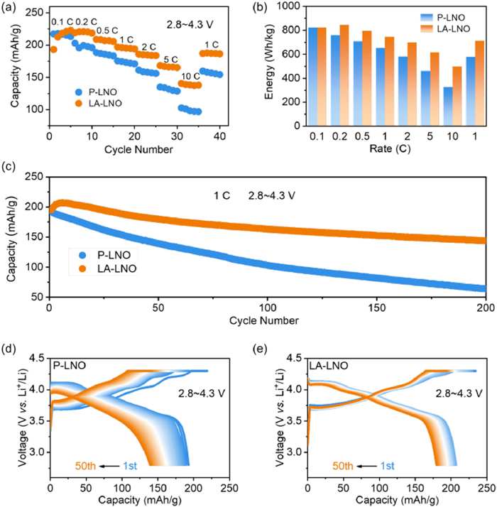
The long-term cycling stability (Fig. 3c) of the assembled cells reveals that the specific capacity of LA-LNO decreases from 195.5 mAh/g to 143.9 mAh/g after 200 cycles. In sharp contrast, the specific capacity of P-LNO drops from 192.7 mAh/g to 64.4 mAh/g. Interestingly, the specific capacity of LA-LNO exhibits a tendency of initial increase followed by a subsequent decrease. Such a continuous activation phenomenon is fairly common in surface-modified cathode materials [32].
To further investigate the charge-discharge process evolution over multiple cycles, continuous charge-discharge curves for both samples from the 1st to the 50th cycle are plotted (Fig. 3d and e). The charge-discharge curves of P-LNO exhibit pronounced changes during the first three cycles, indicating a highly unstable structure, an issue that is effectively addressed in LA-LNO. This observation is corroborated by the dQ/dV curves in Fig. S7c (Supporting information). Additionally, the discharge voltage of P-LNO declines more rapidly. The change in median voltage (Fig. S7d in Supporting information) clearly demonstrates the faster voltage fade in P-LNO relative to LA-LNO. Then, we further compared the cycling performance of P-LNO and LA-LNO with that of Al-only doping in LNO (A-LNO) (Fig. S8 in Supporting information). These phenomena confirm the superiority of the synergistically modified material LA-LNO in terms of cycling performance.
The cyclic voltammetry (CV) results are illustrated in Figs. S9a and b (Supporting information). These findings suggest a reduction in phase transition and minimal capacity fade, which is indicative of superior stability and reversibility in LA-LNO. Electrochemical impedance spectroscopy (EIS) plots in Fig. S9c (Supporting information) feature a semicircle extending from the high-frequency region to the mid-frequency region and a diagonal line in the low-frequency region. The cells after cycling exhibit an additional semicircle in the mid-frequency range (Fig. S9d in Supporting information). The fitted data are presented in Table S5 (Supporting information). Unexpectedly, the total impedance of LA-LNO decreases by 37% after 10 cycles. This impedance reduction mitigates polarization during battery discharge, allowing for higher accessible capacity, thus accounting for the increase in specific capacity observed over the initial few cycles. To accurately demonstrate the diffusion kinetics of lithium ions in the two materials, we performed galvanostatic intermittent titration technique (GITT) characterization (Fig. S10 in Supporting information). By comparing the peak positions in the CV curves in Figs. S9a and b, it is found that LA-LNO has a higher Li+ diffusion coefficient (DLi+) at the key positions where capacity is provided, indicating that LA-LNO can release specific capacity more quickly, which is consistent with its better rate performance.
The SEM images of the electrode fragments after 200 cycles confirm the superior structural stability of LA-LNO (Figs. 4a and b). P-LNO shows significant cracking and holes after cycling, while LA-LNO stays crack-free with intact secondary particles. This is attributed to the formation of smaller primary particles upon Al doping, which effectively mitigates material strain during cycling. Concurrently, the presence of the La4NiLiO8 stabilizes the interface, impedes the structural collapse and surface cracks caused by the direct contact between the electrolyte and the active material. Subsequently, the less nickel dissolution is confirmed by the ICP results (Fig. 4c).
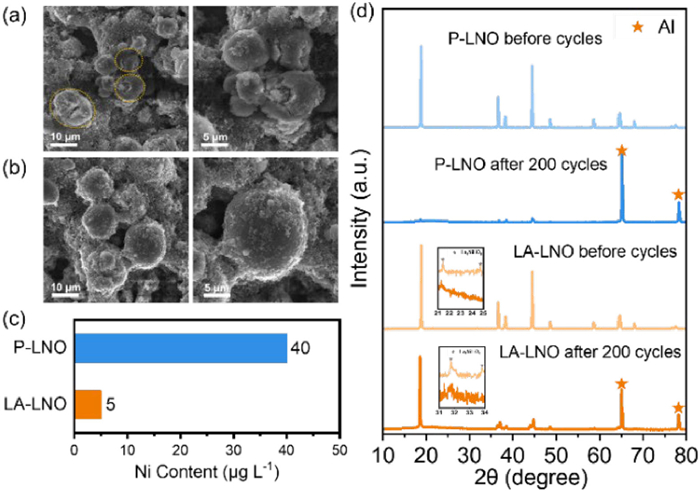
XRD analysis is conducted on the electrodes after 200 cycles to investigate the phase structure changes in P-LNO and LA-LNO (Fig. 4d). A comparison of the diffraction peaks of P-LNO before and after cycling reveals that the (003) and (104) peaks of the unmodified material are substantially diminished and nearly vanish. Similarly, the (003) peak of LA-LNO also exhibits some attenuation, but it retains greater intensity compared to P-LNO. Moreover, the (104) peak of LA-LNO demonstrates a more pronounced advantage, remaining sharp after cycling. This compellingly demonstrates that the structure of P-LNO has severely collapsed, whereas LA-LNO has preserved a layered structure with a relatively intact lithium storage structure and less lithium-nickel mixing. This benefit is ascribed to the fact that Al, once incorporated into the Ni layer, maintains a + 3 oxidation state throughout the valence changes of Ni. Al acts as a fixed charge center, preventing the rearrangement of lithium vacancies and thus mitigating structural deformation during cycling. Furthermore, the locally magnified XRD patterns of LA-LNO indicate that the characteristic peaks of La4NiLiO8 persist distinctly after cycling. This implies that the coating phase continually protects the bulk material and lessens electrolyte-induced corrosion of the cathode material. The comparative results of the XRD spectra reveal that the bulk phase structure and surface interface stability of the material are enhanced following the modification, which provides an understanding of the improved cycling stability and superior rate performance of LA-LNO at the microscopic level.
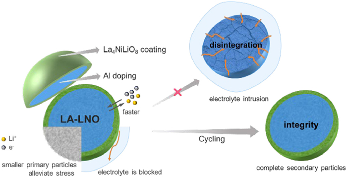
In summary, to solve the issues of poor cycling stability and rate performance of its prototype material LNO, a process combining in situ wet coating with high-temperature lithiation has been developed to achieve synergistic modification of LNO through Al doping and La4NiLiO8 epitaxial coating. Compared with the preparation routes in existing literature (Table S6 in Supporting information), the preparation method proposed in this paper is more practical. A schematic illustration of its action is presented in Fig. 5. Al substituting for Ni reduces structural deformation from Li+/Ni2+ disorder and refines grain size, alleviating stress in phase transformation. The La4NiLiO8 coating acts as a protective barrier, mitigating interfacial side reactions, and reducing battery impedance with high conductivity. Under the synergistic effect of the two, the cycling performance and rate capability of LNO have been improved. This study confirms the feasibility of using a simplified in situ wet synthesis for La/Al-modified materials, highlights the structural stabilization effects of Al doping, and clarifies how the La4NiLiO8 coating lowers battery impedance and reduces Ni dissolution. These findings provide a valuable reference for the synergistic modification of high-nickel and cobalt-free materials.
Doudou Bao: Writing – original draft, Methodology, Investigation, Formal analysis, Data curation. Jinwei Zhou: Writing – original draft, Methodology, Investigation, Formal analysis, Data curation. Ayaz: Writing – review & editing. Li Wang: Writing – review & editing. Xiangming He: Writing – review & editing. Ziang Jiang: Writing – review & editing. Feixiang Wu: Writing – review & editing.
The authors declare that they have no known competing financial interests or personal relationships that could have appeared to influence the work reported in this paper.
The authors gratefully acknowledge the National Natural Science Foundation of China (No. 52172264), and the Science and Technology Innovation Program of Hunan Province (No. 2023RC1016).
Supplementary material associated with this article can be
found, in the online version, at doi:
Global EV Outlook, Analysis-IEA, 2024.
Mineral commodity summaries 2024, U.S. Geological Survey, 2024.
L. Yu, T. Liu, R. Amine, et al., ACS Appl. Mater. Interfaces 14 (2022) 23056–23065. doi: 10.1021/acsami.1c22091
H. Zhao, W.Y.A. Lam, L. Sheng, et al., Adv. Energy Mater. 12 (2022) 2103894. doi: 10.1002/aenm.202103894
H. Li, L. Wang, Y. Song, et al., Small 19 (2023) 2302208. doi: 10.1002/smll.202302208
T. Wang, J. Yang, H. Wang, et al., Adv. Energy Mater. 13 (2023) 2204241. doi: 10.1002/aenm.202204241
F.G.H. Kaufmann, Solid State Ionics 105 (1998) 297–302. doi: 10.1016/S0167-2738(97)00477-3
L. Madec, J. Xia, R. Petibon, et al., J. Phys. Chem. C 118 (2014) 29608–29622. doi: 10.1021/jp509731y
L. de Biasi, A. Schiele, M. Roca-Ayats, et al., ChemSusChem 12 (2019) 2240–2250. doi: 10.1002/cssc.201900032
C.H. Jo, N. Voronina, S.T. Myung, Energ. Storage Mater. 51 (2022) 568– 587. doi: 10.1016/j.ensm.2022.06.024
Q. Hao, F. Du, T. Xu, et al., J. Electroanal. Chem. 907 (2022) 116034. doi: 10.1016/j.jelechem.2022.116034
D. Weber, J. Lin, A. Pokle, et al., J. Electrochem. Soc. 169 (2022) 030540. doi: 10.1149/1945-7111/ac5b38
T. Zhou, H. Wang, Y. Wang, et al., Chem 8 (2022) 2817–2830. doi: 10.1016/j.chempr.2022.07.023
G. Ding, M. Yao, J. Li, et al., Adv. Energy Mater. 13 (2023) 2300407. doi: 10.1002/aenm.202300407
J. Zhou, Y. Chu, W. Liu, et al., ACS Appl. Mater. Interfaces 16 (2024) 13948–13960. doi: 10.1021/acsami.3c17457
C. Geng, D. Rathore, D. Heino, et al., Adv. Energy Mater. 12 (2021) 2103067. doi: 10.1002/aenm.202103067
Y. Zhang, H. Li, J. Liu, et al., J. Energy Chem. 63 (2021) 312–319. doi: 10.3390/ijms23010312
J. Li, Y. Zhu, B. Pang, P. Gao, J. Mater. Sci. 57 (2022) 17722–17734. doi: 10.1007/s10853-022-07777-6
L. Shen, Y. Gu, T. Xu, et al., J. Colloid Interface Sci. 662 (2024) 505–515. doi: 10.1016/j.jcis.2024.01.181
H. Yang, H.H. Wu, M. Ge, et al., Adv. Funct. Mater. 29 (2019) 1808825. doi: 10.1002/adfm.201808825
L. Li, L. Fu, M. Li, et al., J. Energy Chem. 71 (2022) 588–594. doi: 10.1016/j.jechem.2022.04.037
M. Yi, A. Dolocan, A. Manthiram, Adv. Funct. Mater. 33 (2023) 213164. doi: 10.1002/adfm.202213164
H. Cao, F. Du, J. Adkins, et al., Ceram. Int. 46 (2020) 20050–20060. doi: 10.1016/j.ceramint.2020.05.078
Z. Cui, P. Zuo, Z. Guo, C. Wang, A. Manthiram, Adv. Mater. 36 (2024) 2402420. doi: 10.1002/adma.202402420
X.Z. Kong, D.L. Li, E.O. Fedorovskaya, T. Kallio, X.Q. Ren, Int. J. Energy Res. 45 (2021) 10489–10499. doi: 10.1002/er.6536
J. Zhou, Z. Han, Y. Zhang, et al., J. Mater. Chem. A 9 (2021) 3427–3440. doi: 10.1039/d0ta09383a
L. Wang, G. Liu, R. Wang, et al., Adv. Mater. 35 (2023) 2401123.
A. Van der Ven, G. Ceder, Electrochem. Commun. 6 (2004) 1045–1050. doi: 10.1016/j.elecom.2004.07.018
S. Wang, W. Hua, A. Missyul, et al., Adv. Funct. Mater. 31 (2021) 2009949. doi: 10.1002/adfm.202009949
S.P. Lin, K.Z. Fung, Y.M. Hon, M.H. Hon, J. Solid State Chem. 167 (2002) 97– 106. doi: 10.1006/jssc.2002.9624
S. Zhang, J. Wu, N. Jiang, et al., Adv. Energy Mater. 14 (2024) 2401123. doi: 10.1002/aenm.202401123
H. Kobayashi, G. Yuan, Y. Gambe, I. Honma, ACS Appl. Energy Mater. 4 (2021) 9866–9870. doi: 10.1021/acsaem.1c01885

Figure 2 The phase analysis and cross-sectional elemental distribution of the samples. XRD patterns of (a) P-LNO and LA-LNO. Localized magnified spectra of (b, c) characteristic diffraction peaks for La4NiLiO8 coating. (d) SEM image and distribution of different elements for the cross-sections of LA-LNO which obtained by focused-ion-beam (FIB) preparation technique. (e) The results of a line sweep along the line segment in the figure.

Figure 3 The electrochemical performance of two samples. (a) Rate performance and (b) average specific energy at different rates. (c) Comparison of long-term cycling performance. (d, e) Charge-discharge curves for continuous 1–50 cycles, at 1 C (180 mA/g) rate and in the voltage range of 2.8–4.3 V for P-LNO and LA-LNO.

Figure 4 The morphology and phase structure of the cathode electrode piece after 200 cycles at 1 C rate in the voltage range of 2.8–4.3 V. SEM images of the electrode for (a) P-LNO, (b) LA-LNO. (c) Nickel dissolution after cycles for P-LNO and LA-LNO. (d) XRD patterns of before and after cycles.

 扫一扫看文章


扫一扫关注我们
 DownLoad:

 下载:

 下载: