Citation:
Canghai Luo, Chao Wu, Baoling Guo, Yuan Zheng, Ze Yang, Xiaoying Ji, Jianpeng Sheng, Jian Ruan, Peng Zhao, Dongliang Li, Dong Chen. Controlled encapsulation of solid particles in core-shell capsules by millifluidics and assisted by vibrations[J]. Chinese Chemical Letters,
2026, 37(7): 111749.
doi:
10.1016/j.cclet.2025.111749
Controlled encapsulation of solid particles in core-shell capsules by millifluidics and assisted by vibrations
English
Controlled encapsulation of solid particles in core-shell capsules by millifluidics and assisted by vibrations
Department of Medical Oncology, The First Affiliated Hospital, School of Medicine, Zhejiang University, Hangzhou 310003, China
b.
College of Energy Engineering and State Key Laboratory of Clean Energy Utilization, Zhejiang University, Hangzhou 310003, China
c.
Department of Medical Oncology, Senior Department of Oncology, Chinese PLA General Hospital, Beijing 100853, China
d.
Department of Oncology, Longyan First Affiliated Hospital of Fujian Medical University, Longyan 364000, China
e.
Cigar Fermentation Technology Key Laboratory of China Tobacco, China Tobacco Sichuan Industrial Co., Ltd., Chengdu 610100, China
* Corresponding authors. E-mail addresses: 360188228@qq.com (D. Li)
chen_dong@zju.edu.cn (D. Chen). 1 These authors contributed equally to this work.
Received Date:
13 May 2025 Accepted Date:
21 August 2025 Revised Date:
19 August 2025 Available Online:
15 July 2026
Abstract:
Core-shell capsules are excellent carriers, showing good performances in cargo protection and controlled release. However, the controlled encapsulation of solid particles in capsules remains a great challenge, severely limiting their widespread applications. Here, a millifluidic system assisted by periodic vibrations is developed to precisely control the preparation of particle-loaded capsules. A high-frequency low-amplitude vibration is applied to prevent the jamming of solid particles by shaking and a low-frequency high-amplitude vibration is applied to synchronize the feeding of solid particles and the emulsification of capsules by generating a periodic flow pulse. The phase diagrams of particle-loaded capsules are systematically investigated with respect to various experimental parameters to provide guidances for the controlled preparation process. The developed millifluidic system offers a versatile platform to precisely prepare core-shell capsules loaded with different sizes, types and numbers of particles. The prepared particle-loaded capsules possess good biocompatibility, monodispersity, mechanical strength, storage stability and controlled release, paving the way for their widespread applications.
Core-shell capsules are widely used in various fields, including food [1-3], pharmaceutic [4-8] and cosmetic industries [9-12], owing to their capability of cargo protection and controlled release. Recently, the encapsulation of solid particles, such as drug crystal granules [13], insulin-loaded polymer particles [14], metal catalysis particles [15] and enzyme-loaded silica particles [16], in core-shell capsules have attracted a lot of interest, as capsules are excellent carriers for diverse cargos. When encapsulated in core-shell capsules, solid particles are protected from ambient environments, thus increasing their storage time. In addition, solid particles could be released in a desired manner by designing their shell property. However, the encapsulation of solid particles in core-shell capsules is challenging and very different from making multiple emulsions, as solid particles are not fluid and the control of solid particles is difficult [17]. For example, oil-in-water-in-oil double emulsions could be prepared by two-step emulsifications [18,19]. However, the controlled encapsulation of solid particles in capsules, such as controlled number of solid particles, could barely be achieved in the emulsion process by stirring, as solid particles may settle and aggregate in the inner phase due to density mismatch [20], which will result in either empty capsules or capsules with irregular numbers of solid particles. Therefore, to achieve the controlled encapsulation of solid particles in capsules, it is essential to control the feeding of solid particles during the emulsification process [21].
Microfluidic technology, which can precisely control the fluid flows at micron scale [22,23], has shown the capability to control the feeding of fluids and their emulsification into emulsions [24,25]. So far, diverse emulsions, including droplets, core-shell capsules, triple emulsions and so on, have been designed and successfully prepared by microfluidics [26-28]. In addition, the controlled encapsulation of hydrogel particles in droplets, such as one hydrogel particle in each droplet, has also been demonstrated [29]. In the microfluidic device, the channel dimension is comparable to the hydrogel particle diameter and thus hydrogel particles line in a row, ensuring that the feeding of hydrogel particles with a desired number synchronizes with the emulsification of droplets [30].
Despite of the advancements, the controlled encapsulation of solid particles in capsules remains challenging and is barely reported yet [31]. Solid particles are different from hydrogel particles, and they often suffer from sedimentation and jamming, due to density mismatch. In addition, solid particles cannot flow like a fluid, making it very difficult to control their feeding during the emulsification process [32]. Therefore, an advanced microfluidic system for the precise encapsulation of solid particles in capsules remains unavailable [33] and there is a high demand to develop a microfluidic platform to control the feeding of solid particles and the emulsification of capsules simultaneously [34].
In this study, a millifluidic system assisted by periodic vibrations is designed to precisely control the production of core-shell capsules loaded with a desired number of solid particles. A high-frequency low-amplitude vibration is applied to the solid particle container to shake the solid particles dispersed in the inner oil phase and prevent their jamming. A low-frequency high-amplitude vibration is applied to the inner tube to generate a periodic flow pulse, which synchronizes the feeding of solid particles and the emulsification of capsules, thus forming core-shell capsules loaded with solid particles. The controlled preparation of particle-loaded capsules is systematically explored in terms of vibration frequency, amplitude, inner, middle and outer phase flow rates. The prepared capsules possess good biocompatibility, monodispersity, mechanical strength, storage stability and controlled release. Different sizes, types and numbers of particles could controllably be encapsulated in the capsules and then released by mechanical crushing or shell dissolution, showing widespread applications in diverse areas.
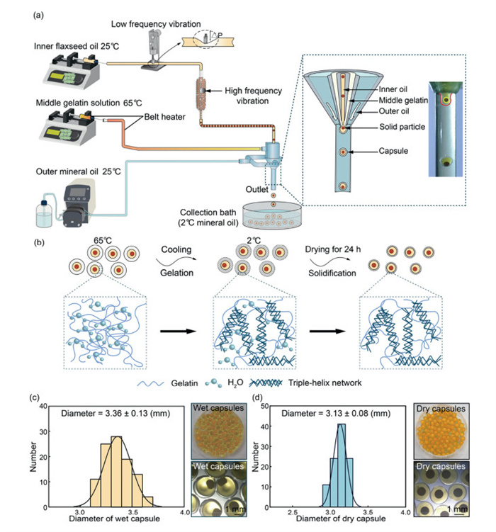
To prepare monodisperse particle-loaded capsules, a millifluidic system assisted by periodic vibrations is developed, as shown in Fig. 1a. The photographs of the 3D-printed millifluidic device and the experimental setup are shown in Figs. S1 and S2 (Supporting information), respectively. Flaxseed oil carrying solid particles, such as glass beads (D = 1.5 mm), is used as the inner phase. 25 wt% gelatin and 8 wt% glycerol in water is used as the middle phase. The outer continuous phase is mineral oil. To encapsule solid particles in the capsules, a low-frequency high-amplitude vibration (frequency = 1 Hz and amplitude = 1.5 mm) is applied to the inner tube, which causes a periodic flow pulse of 13 µL, thus feeding solid particles with a desired number into each capsule. Meanwhile, to prevent the jamming of solid particles, a high-frequency low-amplitude vibration (frequency = 200 Hz and amplitude = 1 mm) is applied to the solid- particle container, which shakes the solid particles and facilitates their movement in the inner oil phase without causing any flow pulses. To avoid the gelation of the gelatin solution at room temperature, the middle tube is wrapped by a belt heater and the middle gelatin phase is heated up to 65 ℃. At the orifice of the 3D printed microfluidic device, the inner and middle phases are emulsified by the shearing force of the outer continuous oil phase to form core-shell capsules with solid particles. If not specified, Qin = 800 µL/min, Qmid = 600 µL/min, Qout = 15 mL/min, fin_vibration = 1 Hz, Ain_vibration = 1.5 mm and Dsolid = 1.5 mm.
Figure 1
Figure 1.
Controlled preparation of monodisperse particle-loaded capsules by a millifluidic system and assisted by periodic vibrations. (a) Experimental setup showing the emulsification of monodisperse capsules with one solid particle. (b) Gelation of particle-loaded capsules upon cooling and solidification after drying. Size distribution of (c) wet and (d) dry capsules. If not specified, Qin = 800 µL/min, Qmid = 600 µL/min, Qout = 15 mL/min, fin_vibration = 1 Hz, Ain_vibration = 1.5 mm and Dsolid = 1.5 mm.
After emulsification, particle-loaded capsules are cooled from 65 ℃ to 2 ℃, causing the gelatin shell to gel, as shown in Fig. 1b. In the gelation state, gelatin molecules self-assemble into a triple-helix structure and form a cross-linked network. The gelatin shell is then dried for 24 h to form solidified capsules. Before drying, wet capsules have an average size of D = 3.36 ± 0.13 mm, as shown in Fig. 1c. After drying, solidified capsules have an average size of D = 3.13 ± 0.08 mm, as shown in Fig. 1d. The good monodispersity of prepared capsules is attributed to the precise control of fluid flows and emulsification process by millifluidics.
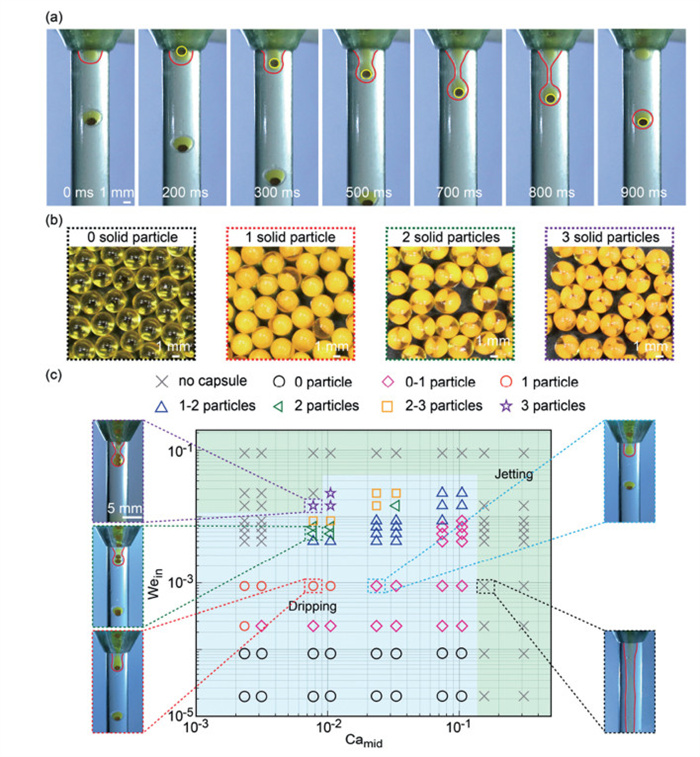
To investigate the formation of core-shell capsules loaded with different numbers of solid particles, the capsule formation process is monitored by a camera. When the emulsification of each capsule is synchronized with the feeding of one solid particle, one-particle capsules are obtained, as shown in Fig. 2a. By tuning the experimental parameters, such as the flow rates of the inner and middle phases, core-shell capsules without and with one, two and three solid particles could be achieved, as shown in Fig. 2b.
Figure 2
Figure 2.
Formation of particle-loaded capsules in different flow regions. (a) Real-time images showing the formation of capsules loaded with one solid particle. (b) Snapshots of particle-loaded capsules without and with one, two and three solid particles. (c) Phase diagram of particle-loaded capsules as a function of Camid and Wein. Particle-loaded capsules are mainly prepared in the dripping region.
To systematically investigate the preparation of particle-loaded capsules in different flow states, the phase diagram is plotted as a function of dimensionless numbers, i.e., Weber number, Wein, and capillary number, Camid, as shown in Fig. 2c. Wein denotes the competition between inertial force and interfacial tension, and Wein = ρU2L/γ, where ρ, U, L and γ are the inner-phase density, inner-phase flow velocity, inner-nozzle diameter and inner/middle interfacial tension, respectively. Camid denotes the competition between viscous drag and interfacial tension, Camid = µU/γ, where µ, U and γ are the middle-phase viscosity, middle-phase flow velocity, and inner/middle interfacial tension, respectively. Both Wein and Camid influence the emulsification of particle-loaded capsules. When Wein or Camid is too large, the flow state will transition from the dripping to jetting regimes.
Overall, core-shell capsules loaded with solid particles are prepared only in the dripping regime (light blue region), while no capsules are formed in the jetting regime (light green region). The synchronization of capsule emulsification and core feeding is crucial for the controlled preparation of particle-loaded capsules. When Camid is kept constant, the number of solid particles increases, as Wein increases and more inner oil and solid particles are encapsulated in each capsule, as shown in the left column of Fig. 2c. When Wein is kept constant, the number of solid particles gradually decreases, as Camid increases and less inner oil and solid particles are emulsified in each capsule, as shown in the right column of Fig. 2c.
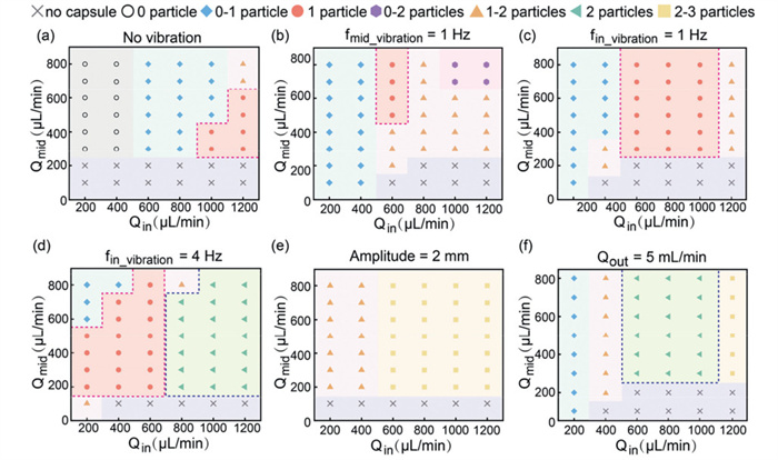
Besides the flow rates, many other experimental parameters could affect the formation of particle-loaded capsules, such as vibration applied to the middle phase, vibration applied to the inner phase, vibration frequency and vibration amplitude. Therefore, the phase diagrams of particle-loaded capsules under different conditions are investigated as a function of the flow rates of the inner and middle phases, i.e., Qin and Qmid. When there is no vibration, the region of particle-loaded capsules in the phase diagram is small, as shown in Fig. 3a. When a low-frequency high-amplitude vibration is applied to the middle phase, capsules are formed in a large region but with a small one-particle region, suggesting that fmid_vibration is beneficial for capsule formation but not for solid particle encapsulation, as shown in Fig. 3b. In contrast, when the low-frequency high-amplitude vibration is applied to the inner phase, one-particle capsules could be prepared in a large region, as fin_vibration could synchronize capsule emulsification and core feeding, as shown in Fig. 3c.
Figure 3
Figure 3.
Phase diagrams of particle-loaded capsules under different conditions. Phase diagrams of particle-loaded capsules (a) without vibration, (b) with fmid_vibration = 1 Hz, (c) fin_vibration = 1 Hz and (d) fin_vibration = 4 Hz. Phase diagrams of particle-loaded capsules with (e) Ain_vibration = 2 mm and (f) Qout = 5 mL/min.
When fin_vibration increases from 1 Hz to 4 Hz, the number of solid particles in each capsule increases under constant inner and middle flow rates, as shown in Fig. 3d. Large regions of one-particle and two-particle capsules are observed, suggesting that higher fin_vibration leads to higher particle feeding rate. When the vibration amplitude, Ain_vibration, increases from 1.5 mm to 2 mm, more solid particles are fed into the capsules, but without synchronizing with the capsule emulsification process, thus leading to the irregular formation of one-particle, two-particle and three-particle capsules, as shown in Fig. 3e. When the core feeding rate is kept constant and Qout decreases from 15 mL/min to 5 mL/min, the shearing force and thus the capsule emulsification rate decreases, leading to the formation of capsules with more cores, as shown in Fig. 3f. Two-particle capsules could be achieved in a large region.
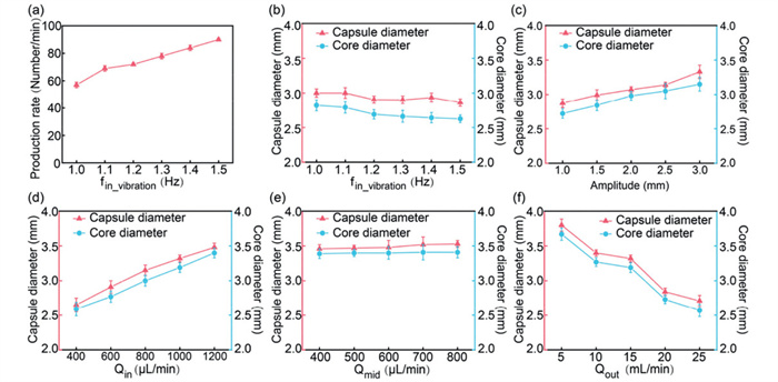
The size of particle-loaded capsules could be adjusted by tuning the experimental parameters, such as fin_vibration, Ain_vibration, Qin, Qmid and Qout. Since the capsule emulsification rate is mainly determined by fin_vibration, the production rate increases proportionally as fin_vibration increases, as shown in Fig. 4a. Meanwhile, the capsule diameter, Dcapsule, and the core diameter, Dcore decrease as the feeding rates of the inner and middle phases remain unchanged, as shown in Fig. 4b. When fin_vibration is kept constant at 1 Hz, the increase of Ain_vibration will cause the feeding of more solid particles into each capsule, thus leading to the increases of Dcapsule and Dcore, as shown in Fig. 4c. When Qin increases, Dcapsule and Dcore gradually increase, as the feeding rate of the inner oil phase increases, as shown in Fig. 4d. Interestingly, Dcapsule only slightly increases and Dcore remains unchanged, when Qmid increases, as shown in Fig. 4e. This is because that the production rate is synchronized with fin_vibration and the increase of the middle phase only slightly contributes to the increase of the capsule size. When Qout increases, Dcapsule and Dcore gradually decrease, as shown in Fig. 4f. The inner and middle phases are emulsified into smaller capsules, as the shearing force of the outer continuous phase becomes stronger.
Figure 4
Figure 4.
Optimization of particle-loaded capsules by experimental parameters. (a) Dependence of production rate on fin_vibration. Dependences of capsule and core diameters on (b) fin_vibration, (c) Ain_vibration, (d) Qin, (e) Qmid and (f) Qout. Data are presented as mean ± standard deviation (SD) (n = 20).
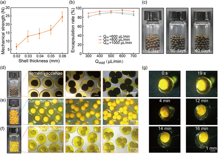
Dried particle-loaded capsules possess a good mechanical strength, which increases as the shell thickness increases, as shown in Fig. 5a. The good mechanical strength is attributed to the cross-linked triple-helix structure of gelatin molecules in the shell. In addition, the presence of glycerol as plasticizer could also improve the mechanical strength. The encapsulation rate of one particle in each capsule is higher than 80% and could reach up to 96% under optimized conditions, as shown in Fig. 5b. There is no change observed in dried particle-loaded capsules over 40 days at room temperature, suggesting a good storage stability, as shown in Fig. 5c.
Figure 5
Figure 5.
Encapsulation of different solid particles in core-shell capsules. (a) Mechanical strength of particle-loaded capsules with different shell thicknesses. Data are presented as mean ± SD (n = 20). (b) Encapsulation rate of one-particle capsules prepared at different Qin and Qmid. Data are presented as mean ± SD (n = 120). (c) Storage stability of capsules over time. Photograph and optical microscope images of core-shell capsules encapsulating (d) semen vaccariae (D = 1.5 mm), (e) curcumin particles (D = 1.8 mm) and (f) hydrogel particles loaded with probiotics (D = 1.6 mm). (g) Controlled release of curcumin particle-loaded capsules in water at 37 ℃.
Core-shell capsules are versatile carriers. Cargos with different sizes, e.g., semen vaccariae (~1.5 mm) and curcumin particles (~1.8 mm), different constituents, e.g., probiotics-loaded hydrogel particles (~1.6 mm), and different numbers of particles, e.g., one particle, two particles and three particles, could controllably be encapsuled in the capsules, as shown in Figs. 5d–f. Since all materials used are Food and Drug Administration (FDA)-approved, the gelatin capsules have a good biocompatibility. Encapsulated cargos could be released by mechanical rupture, such as chewing. Alternatively, encapsulated cargos could be released by shell dissolution, such as oral administration in 37 ℃ water, making the capsules suitable for controlled release, as shown in Fig. 5g. The capsules also show pH-dependent release behaviors at physiological temperature (37 ℃), as shown in Fig. S3 (Supporting information). The particle-loaded capsules are dissolved faster in acidic solution (pH 3) than in alkaline solution (pH 8). The dependence of capsule release on pH is attributed to the gelatin's isoelectric point at pI ≈ 5.
A millifluidic system assisted by vibrations is designed to prepare core-shell capsules loaded with a desired number of solid particles. A high-frequency low-amplitude vibration is indispensable to prevent the jamming of solid particles by shaking and a low-frequency high-amplitude vibration is essential to synchronize the feeding of solid particles and the emulsification of capsules by generating a periodic flow pulse. The effects of experimental parameters on capsule properties are systematically studied for the controlled preparation. The millifluidic system assisted by periodic vibrations provides a versatile platform to encapsulate different sizes, types and numbers of particles in core-shell capsules. The prepared particle-loaded capsules demonstrate good biocompatibility, monodispersity, mechanical strength, storage stability and controlled release, making them ideal carriers. The vibration-assisted millifluidic system plays a pivotal role in enabling the controlled encapsulation of cargos in capsules and shows great promises for advancing the applications of capsules. Future developments of the millifluidic system with the capability of high-throughput production will further address the scalability challenges to meet the growing industrial demands.
Declaration of competing interest
The authors declare that they have no known competing financial interests or personal relationships that could have appeared to influence the work reported in this paper.
This work was supported by the National Natural Science Foundation of China (No. 22278352), China Tobacco Sichuan Industrial Co., Ltd. (No. 20202303BA530) and Guangxi Baifei Dairy Co., Ltd.
Supplementary materials
Supplementary material associated with this article can be found, in the online version, at doi:10.1016/j.cclet.2025.111749.
B. Srividya, C. Sowmya, C. Surya Prakash Reddy, Int. J. Pharm. Drug Anal. 2 (2014) 727–733.
[34]
C.H. Luo, Y. Zheng, R.R. Liu, et al., Chem. Eng. Sci. 311 (2025) 121578. doi: 10.1016/j.ces.2025.121578
Figure 1
Controlled preparation of monodisperse particle-loaded capsules by a millifluidic system and assisted by periodic vibrations. (a) Experimental setup showing the emulsification of monodisperse capsules with one solid particle. (b) Gelation of particle-loaded capsules upon cooling and solidification after drying. Size distribution of (c) wet and (d) dry capsules. If not specified, Qin = 800 µL/min, Qmid = 600 µL/min, Qout = 15 mL/min, fin_vibration = 1 Hz, Ain_vibration = 1.5 mm and Dsolid = 1.5 mm.
Figure 2
Formation of particle-loaded capsules in different flow regions. (a) Real-time images showing the formation of capsules loaded with one solid particle. (b) Snapshots of particle-loaded capsules without and with one, two and three solid particles. (c) Phase diagram of particle-loaded capsules as a function of Camid and Wein. Particle-loaded capsules are mainly prepared in the dripping region.
Figure 3
Phase diagrams of particle-loaded capsules under different conditions. Phase diagrams of particle-loaded capsules (a) without vibration, (b) with fmid_vibration = 1 Hz, (c) fin_vibration = 1 Hz and (d) fin_vibration = 4 Hz. Phase diagrams of particle-loaded capsules with (e) Ain_vibration = 2 mm and (f) Qout = 5 mL/min.
Figure 4
Optimization of particle-loaded capsules by experimental parameters. (a) Dependence of production rate on fin_vibration. Dependences of capsule and core diameters on (b) fin_vibration, (c) Ain_vibration, (d) Qin, (e) Qmid and (f) Qout. Data are presented as mean ± standard deviation (SD) (n = 20).
Figure 5
Encapsulation of different solid particles in core-shell capsules. (a) Mechanical strength of particle-loaded capsules with different shell thicknesses. Data are presented as mean ± SD (n = 20). (b) Encapsulation rate of one-particle capsules prepared at different Qin and Qmid. Data are presented as mean ± SD (n = 120). (c) Storage stability of capsules over time. Photograph and optical microscope images of core-shell capsules encapsulating (d) semen vaccariae (D = 1.5 mm), (e) curcumin particles (D = 1.8 mm) and (f) hydrogel particles loaded with probiotics (D = 1.6 mm). (g) Controlled release of curcumin particle-loaded capsules in water at 37 ℃.

 DownLoad:

 下载:
下载:


 下载:
下载:
