Figure 1.
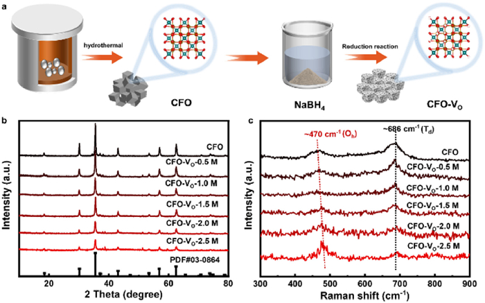
Synthesis method and structure characterization. (a) Schematic illustration of fabricating CFO-VO. (b) XRD patterns and (c) Raman spectra of CFO and CFO-VO by using different NaBH4 concentrations.
Magnetic field enhanced electrocatalytic oxygen evolution of CoFe2O4 with tunable oxygen vacancy concentrations
Xiangyang Zou , Ping Guo , Yuanyuan Zhang , Feng Gao , Ping Xu

Hydrogen energy, recognized as an ideal candidate for future energy storage and supply, offers advantages such as high energy density and environmental cleanliness [1–3]. Electrochemical water splitting is a green hydrogen production pathway, involving the hydrogen evolution reaction (HER) and the oxygen evolution reaction (OER) as two key half-reactions [4,5]. The OER process is particularly challenging due to its inherently sluggish kinetics and high activation barrier, stemming from the complex four-electron transfer process and the formation of O–O bonds [6]. Recent studies have highlighted the pivotal role of electron spin polarization in OER processes, where manipulating spin-polarized electrons can optimize electron transfer pathways and intermediate adsorption behaviors [7–9]. This has sparked interest in leveraging magnetic catalysts to enhance OER activity through external magnetic field, offering a novel pathway to accelerate reaction kinetics and thermodynamics.
Ferromagnetic or ferromagnetic-like catalysts have been extensively investigated due to their ability to provide spin-polarized electrons, as the concentration of one spin (e.g., ↑) is much higher than the other (↓). For instance, the formation of O2 (↑↑) requires two parallel-spin electrons in OER. Ferromagnetic materials can directly supply matched spin states, thereby lowering the reaction energy barrier [10]. Additionally, magnetic field-induced domain wall rotation and magnetic domain alignment can reduce electron scattering and accelerate the transport of spin-polarized electrons [11–13]. Typical magnetic catalysts mainly include single metals such as Fe, Co, Ni, and their alloys. However, their practical applications are limited by poor intrinsic activity, agglomeration tendency, and surface reconstruction, which further complicate mechanistic studies of magnetic field-enhanced OER process. High-performance OER electrocatalysts typically exhibit weak magnetic responses, such as NiFe-layered double hydroxides (NiFe-LDH) and transition metal chalcogenides [14–17]. To address this issue, researchers have employed a core (magnetic material)-shell (catalyst) structure to induce spin pinning effect [18–20], which align the magnetic domains of the catalytic layer in a magnetic field. However, the thickness of the catalytic layer needs to be precisely controlled, an overly thick shell can diminish the magnetic response, imposing higher requirements for the synthesis of magnetic catalysts. Based on the aforementioned challenges, spinel ferrites have emerged as an ideal model system for studying magnetic field-assisted OER due to their low cost, superior stability, and tunable magnetic properties [21]. Galán-Mascarós et al. found that a series of ferromagnetic ferrites exhibit enhanced OER activity under the magnetic field, and the improvement positively correlated with their saturation magnetization (Ms) [22]. Further, Liu et al. validated this trend by manipulating the Ms of NiCo2-xFexO4 through iron doping strategies [23]. Our group adopted single-domain ferromagnetic CoFe2O4 as the catalytic model, revealing coercivity (Hc) as another crucial parameter affecting the enhancement effect of the magnetic field [24]. Materials with high Hc can sustain more ordered spin-polarized states, leading to more pronounced kinetic improvement under the magnetic field. Xu et al. compared the OER performance of ferromagnetic CoFe2O4, antiferromagnetic Co3O4, and paramagnetic IrO2 under the magnetic field, confirming that only ferromagnetic materials enable effective spin-electron filtration to regulate electron transfer process [25]. Additionally, Chen et al. pioneered the application in-situ X-ray spectroscopy to capture the spin state evolution of CoFe2O4 during the OER process in a magnetic field [26]. They discovered that the 3d electrons of Co exhibited significant spin responsiveness and confirmed that M(Oh)-O(1)-M(Oh) was an efficient spin-selection channel. These studies demonstrate that spinel ferrites can act as spin-selective filters in magnetic field-assisted OER. Furthermore, magnetic parameters including Ms and Hc play a decisive role in the magnetic field enhancement effect. A deeper understanding of their synergistic mechanisms or dominant effect is crucial for designing highly efficient magnetic catalysts. Notably, strategies such as doping (e.g., Fex-Ni1-xCo2O4) [27,28] and defect engineering (e.g., LaCoO3-Ov) [29–31] can synergistically optimize both the intrinsic activity and magnetic properties of catalysts. However, systematic insights into the quantitative structure-magnetic-activity relationships remain limited.
Herein, we engineered oxygen vacancies (VO) in CoFe2O4 as a model system to investigate the relationship between magnetic properties and the enhancement of OER activity by the magnetic field. Our results demonstrated that the increase in VO was accompanied by an enhancement of Ms and a decrease of Hc. Under an appropriate condition of Ms and Hc, the maximum enhancement of magnetocurrent (MC~365%) was obtained. Analysis of the overpotential variation under magnetic field versus Ms and Hc exhibited that relatively small Ms modifications induce substantial overpotential reductions, identifying Ms as the dominant magnetic parameter controlling field-enhanced OER. More importantly, we discovered the VO balance mechanism in the OER process under the magnetic field. That is, the magnetic field enhances the reaction kinetics through charge transport effect and magnetohydrodynamic (MHD) effect, generating more high-valent Co ions to compensate for the charge imbalance caused by VO filling, maintaining the stability of VO and keeping the efficient adsorption-conversion process of the catalyst for the reactants.
Synthesis of CoFe2O4 (CFO) nanocrystals: CFO nanocrystals were prepared by the hydrothermal method according to previous literature [24]. In a representative synthesis, FeCl3·6H2O (4 mmol, 1.08 g), CoCl2·6H2O (2 mmol, 0.48 g), and NaOH (20 mmol, 0.8 g) were dissolved in 7 mL DI water at ambient temperature. Ethylenediamine (14 mL, ≥99%) was then added slowly under stirring, forming a black colloidal suspension after 30 min of homogenization. Then the homogeneous suspension was hydrothermally treated in a sealed Teflon-lined reactor at 110 ℃ for 15 h. After cooling to ambient temperature, the slurry was processed through filtration, centrifugation, washing cycles, and vacuum drying to produce CFO nanocrystals.
Synthesis of oxygen vacancies in CoFe2O4 (CFO-Vo): The CFO-Vo catalysts were prepared by the reduction method with NaBH4 solution. CFO catalysts were dissolved respectively in NaBH4 aqueous solutions of 0.5–2.5 mol/L, and an appropriate amount of NaOH was added to inhibit hydrolysis. The reduction process was maintained for 1 h under magnetic stirring. The suspension was filtered, washed, and then vacuum-dried for 12 h to obtain five CFO-VO materials, which were named CFO-VO-0.5 M, CFO-VO-1.0 M, CFO-VO-1.5 M, CFO-VO-2.0 M, and CFO-VO-2.5 M.
The crystal structures were analyzed by X-ray diffraction (XRD, Panalytical X'PERT Pro) using Cu Kα radiation (λ = 1.5418 Å) over a 2θ range of 10°−80°. Raman spectra was acquired on a Renishaw inVia spectrometer equipped with a 532 nm laser (5 mW power) under ambient conditions. Morphological characterization was performed using transmission electron microscopy (TEM, Tecnai G2 F30) at 200 kV acceleration voltage. Magnetic properties were evaluated with a vibrating sample magnetometer (VSM, LakeShore 7404) applying fields up to ±15 kOe at 300 K. X-ray photoelectron spectroscopy (XPS, Thermo Scientific Escalab 250Xi) measurements utilized monochromatic Al Kα radiation (hν = 1486.6 eV). Electron paramagnetic resonance (EPR) analysis of oxygen vacancies was conducted on a Bruker EMXplus X-band spectrometer (9.85 GHz) at room temperature (298 K), employing 2 mW microwave power.
A catalyst ink was prepared by dispersing 5 mg CFO-VO powder in a mixed solvent system containing 650 µL deionized water, 350 µL isopropanol, and 30 µL Nafion (5 wt%), followed by 30 min of ultrasonication in an ice-water bath. The homogeneous slurry was drop-cast (50 µL) onto hydrophilic carbon cloth (1 × 1 cm2) and infrared-dried to form the working electrode, the loading capacity is 0.25 mg/cm2. The OER test under the magnetic field was conducted using a vibrating sample magnetometer (VSM, 0–14,000 G) coupled with electrochemical work to in situ collect electrochemical data. Electrochemical measurements were conducted in a standard three-electrode configuration using 1.0 mol/L KOH electrolyte, Hg/HgO and graphite rod were used as the reference electrode and the counter electrode, respectively. Linear sweep voltammetry (LSV) was performed at 5 mV/s. All LSV measurements were subjected to 85% iR compensation to ensure the accuracy of the intrinsic activity of the catalyst and the comparability of electrochemical data. Electrochemical impedance spectroscopy (EIS) covered 0.1–106 Hz frequencies with 5 mV amplitude. Electrochemical double-layer capacitance (Cdl) was derived from cyclic voltammetry (CV) scans across the non-Faradaic potential region at incrementally increasing scan rates of 10, 20, 40, 60, 80, 100, 120, 150 mV/s. The charging current (Δj = ja - jc) at the center potential was plotted against the scan rate to obtain the slope, which corresponds to Cdl. The electrochemical active surface area (ECSA) was calculated using the formula:
|
|
(1) |
where the Cs is the specific capacitance of a flat electrode (typically 20–60 µF/cm2 in aqueous electrolytes. For this study, we adopted 40 µF/cm2 as the standard value. The MC was calculated with the following equation:
|
|
(2) |
A series of CoFe2O4 with VO (CFO-VO) were synthesized via a hydrothermal method followed by reduction using aqueous solutions of NaBH4 with different concentrations (Fig. 1a). X-ray powder diffraction (XRD) was performed to confirm their crystal structures, which match well with the standard card (JCPDF No. 03–0864) of CoFe2O4 (Fig. 1b), indicating that the obtained samples were free of impurities. As the concentration of NaBH4 solution increased, the XRD diffraction peak intensities of the samples progressively weakened, suggesting that the crystal structure changed of the materials under the strong reducing environment, ultimately resulting in crystallinity degradation. Furthermore, the structure of CFO-VO was affirmed by Raman spectra, the peak positioned at ~470 cm-1 and ~686 cm-1 were assigned to the vibration of lattice oxygen at the octahedral (Oh) sites and tetrahedral (Td) sites, respectively (Fig. 1c) [32,33]. Notably, the enhancement of Raman mode at Oh sites and weakening of Td sites as the increase of VO concentration in CFO-VO can be attributed to the preferential formation of VO at Oh sites, which locally polarizes the remaining M-O bonds and disrupts long-range symmetry [34,35]. Additionally, VO in CoFe2O4 induces local contraction of M-O bonds, evidenced by Raman blue shift of Oh-site mode.
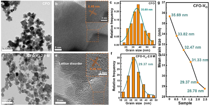
Transmission electron microscopy (TEM) images revealed that the five CFO-VO nanocrystals have the same cubic morphology as CFO (Figs. 2a and d, Figs. S1a-d in Supporting information). However, the CFO nanoparticles were fragmented when reduced with a high concentration of NaBH4 (2.5 mol/L), attributed to the disruption of the crystal structure caused by the generation of a large number of VO. High-resolution transmission electron microscope (HRTEM) exhibited consistent lattice spacings of 0.48 nm across all synthesized CFO and CFO-VO samples, corresponding to the (111) crystal plane of the inverse spinel-structured CFO (Figs. 2b and e, Figs. S1e-h in Supporting information). As the degree of reduction increases, the lattice fringes at the edges of the particles became blurred, indicating a deterioration in the crystallinity of the samples. According to previous reports, the particle size of CFO is positively correlated with coercivity [24]. Therefore, the particle size change induced by VO has been further analyzed. The Gaussian particle size distribution plots (Figs. 2c and f, Figs. S1i-l in Supporting information) indicated that the CFO and five CFO-VO samples belong to single-domain nanocrystals (the critical size of single-domain CFO crystals is 40 nm) [36]. As the vacancy concentration increases, the particle size decreases, which may lead to a reduction in coercivity (Fig. 2g).
To confirm the successful introduction of VO and the resulting changes in elemental valence states, X-ray photoelectron spectroscopy (XPS) was used to further analyze CFO and five types of CFO-VO samples. XPS survey showed the intensity of O 1s peak in CFO-VO weakens with the increase of NaBH4 solution concentration, illustrating the generation of VO in CFO (Fig. S2 in Supporting information) [37]. In more detail, the O 1s high-resolution spectra of CFO were divided into three peaks at 529.9, 531.1 and 532.1 eV, corresponding to lattice oxygen (OL), VO and surface adsorbed oxygen, respectively (Fig. 3a and Fig. S3a in Supporting information) [38]. The peak area was fitted by Gaussian function, and the proportions of three forms of oxygen in CFO and five CFO-VO samples were obtained (Table S1 in Supporting information and Fig. 3d). The proportion of VO increases from 14.3% (CFO) to 47.6% (CFO-VO-2.5 M) with stronger reduction, demonstrating that the content of VO can be effectively controlled via reduction tuning. Subsequently, the Co 2p high-resolution spectra were analyzed, the peaks at 780.57 and 795.57 eV are associated with the Co3+, and the peaks at 783.65 and 797.50 eV are ascribed to Co2+ (Fig. 3b and Fig. S3b in Supporting information) [39,40]. Notably, a relatively higher Co2+/Co3+ ratio of CFO-VO-2.5 M (1.39) was obtained as compared to CFO (0.57), confirming Co3+→ Co2+ reduction during the process of NaBH4 etching [41]. The aforementioned process may lead to a migration of Co2+ from Oh to Td sites, thus reducing magnetic anisotropy and lowering coercivity [42]. Next, the XPS spectra of Fe 2p were deconvoluted in Fig. 3c and Fig. S3c (Supporting information), the characteristic peaks at binding energies of 709.5 and 712.1 eV were attributed to Fe2+ and Fe3+ [43], respectively. Similarly, the value of Fe2+/Fe3+ increased from 0.75 (CFO) to 2.45 (CFO-VO-2.5 M). To further verify the presence of VO in CFO, electron paramagnetic resonance (EPR) measurement was performed on CFO and CFO-VO-2.0 M. The results confirm that the NaBH4 etching process effectively introduced VO, as evidenced by the increased EPR signal intensity (g = 2.003) in CFO-VO-2.0 M (Fig. 3e).

To analyze the influence of VO on the magnetic properties of the catalysts, the hysteresis loops of CFO and a series of CFO-VO were measured (Fig. 3f). CFO with varying concentrations of VO exhibited significant changes in both saturation magnetization (Ms) and coercivity (Hc), with detailed parameters summarized in Table S2 (Supporting information). With the increase of VO concentration, the Ms of CFO-VO increased linearly from 59 emu/g to 71 emu/g, which was attributed to the cancellation of the spin restriction of Fe-O-Fe (Fig. 3f). In detail, the Fe3+(Oh)-O2--Fe3+ (Td) linkage stabilizes the structure via partial covalent bonds, enforcing antiferromagnetic order. When a spin-up cation at the Td site overlaps with the spin-down 2p orbital of O, the remaining spin-up 2p electron can only bond with a spin-down cation at the Oh site. VO generation disrupts this spin alignment, suppressing superexchange effect and boosting Ms [44]. In addition, the VO-induced coercivity decrease (7576 → 599 Oe, Table S2 in Supporting information) follows the size dependence characterization of single-domain CFO nanoparticles, as evidenced by both our prior work and the current particle size analysis [24]. Thus, oxygen vacancy engineering enables concurrent tuning the Ms and Hc of CFO, offering complete insight into how magnetic properties correlate with magneto-enhanced OER activity.
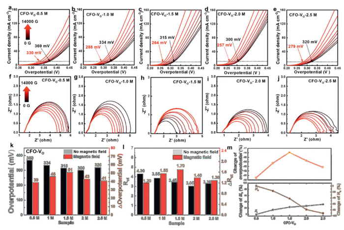
To investigate the relationship of oxygen defect-magnetic parameter-OER activity under the magnetic field, the OER performance of five CFO-VO catalysts was tested under a self-designed magnetic field-electrochemical device (Fig. S4 in Supporting information). The initial overpotentials of the five CFO-VO samples were 369, 334, 315, 300 and 320 mV for delivering a current density of 10 mA/cm2, respectively, demonstrating that proper Vo concentration can improve the OER activity of the catalysts (Figs. 4a-e). With the increase of the magnetic field intensity from 0 to 14,000 G, the overpotentials for delivering a current density of 10 mA/cm2 were decreased by 39 mV (CFO-VO-0.5 M), 46 mV (CFO-VO-1.0 M), 51 mV (CFO-VO-1.5 M), 43 mV (CFO-VO-2.0 M), and 41 mV (CFO-VO-2.5 M), respectively. Also, Nyquist plots indicated that the charge transfer resistance (Rct) can be effectively decreased with an increase in the intensity of the magnetic field, suggesting that the magnetic field accelerates the interface charge transfer process (Figs. 4f-j). Notably, the solution resistance (Rs) remained virtually unchanged under the magnetic field, effectively ruling out the possibility that the observed activity enhancement originated from electrode positional changes. The specific numerical changes in overpotential and Rct with and without a magnetic field are shown in Figs. 4k and l. To quantify the relationship between the performance enhancement of OER and the magnetic structure of the catalysts, a graph was plotted using the percentage reduction in overpotential relative to the corresponding changes in Ms and Hc. Fig. 4m illustrated that changes in both Hc and Ms affect the magnetic field assisted-OER activity. When the etching concentration of NaBH4 is 1.5 mol/L, the overpotential decrease the most (16.1%), corresponding to a 42.21% decrease in Hc and a 22.98% increase in Ms. Subsequently, the Hc drops by nearly 90%, and the Ms increases by 31.7% when the etching is increased to 2.5 mol/L, with the corresponding change in overpotential still remaining at 12.8%, indicating that Ms may play a decisive role in the increment of OER activity. In addition, stability is an important indicator for catalyst evaluation. We adopted a chronopotentiometry test under the magnetic field to observe the stability of the CFO-VO-2.0 M catalyst (Fig. S5 in Supporting information). The catalyst exhibits excellent stability under operational conditions, even after prolonged exposure to the magnetic field (1.4 T) for 1.2 h, with the MC continues to rise, confirming that no significant particle detachment from the electrode surface occurs. Notably, the MC will not immediately return to its initial state due to the high coercivity of the material after the external magnetic field is removed. On the contrary, a hysteresis effect was observed, with the current density gradually decaying within 2.7 h and then stabilizing at the initial level. This behavior is consistent with the magnetism of the catalyst.
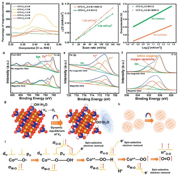
To clarify the mechanism of the magnetic field enhanced-OER, the electrochemical results and spectroscopic characterizations with and without the application of the magnetic field were further analyzed. Fig. 5a exhibited the MC extracted from the LSV curves. The maximum magnetic enhancement effect is approximately 365% for CFO-VO-1.5 M. After reaching the enhancement threshold, the relative MC decreased, assigned to diffusion limitations provoked by a very intense O2 gas bubbling. As expected, the percentage increase in MC of the five samples was consistent with the downward trend of overpotential. Combined with the above electrochemical tests, the CFO-VO-2.0 M sample eventually exhibited the optimal OER performance (257 mV@10 mA/cm2) under a magnetic field of 14,000 G, surpassing most CoFe2O4-based electrocatalysts designed with complex structures (Table S3 in Supporting information). Therefore, the subsequent mechanism investigation was all based on the CFO-VO-2.0 M sample. Notably, the alignment of magnetic moments induced by a magnetic field can lead to changes in the volume or shape of nanoparticles [45,46]. Consequently, the double-layer capacitance (Cdl) was measured to evaluate the electrochemically active surface area (ECSA). The Cdl values for the CFO-VO-2.0 M without and with a magnetic field of 14,000 G were 1.04 and 1.26 mF/cm2, respectively (Fig. 5b, Figs. S6a and b in Supporting information). The corresponding ECSA values were calculated (Fig. S6c in Supporting information), which were 25.8 cm2 and 31.3 cm2, indicating that the lattice within the magnetic domains of CFO-VO-2.0 M undergoes distortion under the action of the magnetic field, resulting in an increase in the ECSA of the catalyst and the expansion of the active sites. ECSA-normalized LSV curves (Fig. S6d in Supporting information) showed that the OER activity of CFO-VO-2.0 M under the magnetic field was still significantly higher than that without the magnetic field, indicating that the change in the ECSA is not the decisive factor for the magnetic field-enhanced OER. Furthermore, the Tafel slope of the CFO-VO-2.0 M catalyst was analyzed with and without a magnetic field. The Tafel slope decreased from 70.7 mV/dec to 54.3 mV/dec under the magnetic field (Fig. 5c), demonstrating that the magnetic field accelerated reaction kinetics through enhanced electron transfer rates, and the rate-determining step (RDS) changed from a mixed of the first/second electrons transfer step to the second electron transfer step. According to (3), (4), the magnetoresistance (MR) of the materials is related to the magnetic parameters. In a single-domain system, anisotropic equivalent field is equal to Hc. The decrease in Hc and the increase in Ms will lead to a reduction in RM, indicating that the change in magnetic parameters optimizes the conductivity under the magnetic field.
|
|
(3) |
L is the magnetic circuit length, µ is the relative permeability, and A is the magnetic circuit cross-sectional area.
|
|
(4) |
Ms and Hk are the magnetic crystal saturation magnetization and anisotropic equivalent field, respectively.
To comprehensively understand the influence of magnetic effect on the OER process, the phase and valence state of the catalyst after magnetic field-assisted OER were analyzed. The XRD pattern and Raman spectra observed that the phase and bond structure of the catalyst did not change after OER with and without a magnetic field, indicating that no surface reconstruction phenomenon occurred (Fig. S7 in Supporting information). Next, XPS was detected to explore the changes in the valence state content of the catalysts after the OER (Fig. S8 in Supporting information). In the case of changing from no magnetic field to applied magnetic field, the value of Co3+/Co2+ changed from 1.27 to 2.30, while the value of Fe3+/Fe2+ remained basically unchanged, manifesting that Co is the main active site of OER, and the magnetic field promoted the oxidation process of Co2+ (Figs. 5d and e). Importantly, the content of VO (16.9%) after the OER decreases significantly compared with that before the OER (36.8%) with no magnetic field (Fig. 5f). However, the content of VO (32.8%) can be maintained basically unchanged when a magnetic field is applied, which may involve a dynamic equilibrium mechanism of VO induced by the magnetic field. Specifically, VO typically acts as active sites, promoting the adsorption and activation of reactants (OH- and H2O) [47,48], forming lattice oxygen and releasing protons and electrons (Fig. 5g). When the VO was filled, the local charge may change, necessitating the oxidation of metal ions (such as Co2+ → Co3+) to balance the charge. Nevertheless, the oxidation rate of Co2+ may be relatively slow in the absence of a magnetic field, resulting in insufficient charge compensation and the inability to regenerate VO in a timely manner. When a magnetic field is applied, more Co3+ is generated, thereby providing sufficient positive charges to compensate for the negative charges brought about by the filling of VO, maintaining the dynamic balance of VO. Besides, the magnetohydrodynamic (MHD) effect reduces the ineffective adsorption or filling of adsorbed species at VO. The process of Co2+ → Co3+ in OER being accelerated through dual mechanisms. (1) The Lorentz force can act on charged species, accelerating the mass transfer of OH- and promoting the OER process. (2) The magnetic field can drive the ferromagnetic spin order and reduce the electron transfer resistance, thereby achieving rapid spin-polarized electron transfer (Fig. 5h). The detailed OER pathway is shown in Fig. 5i. The O–O coupling process is the rate-limiting step of OER, which occurs through the attack of OH- on the ligand oxygen radical [49]. The spin-up p electron in the ∙OH radical pairs with the spin-down p electron in the Co-O∙ to form a σOnullO bond, and the spin selectively removes a spin-down electron. The subsequent formation of Co-OOH intermediates and the dehydrogenation process also follow a similar spin-sensitive electron transfer. Two spin-up electrons with parallel spin directions will remain in the antibond π* orbital, thereby leading to the formation of triplet state O2 in a low barrier manner.
In conclusion, this work successfully modulated the magnetic properties of CFO nanocrystals using defect engineering by disrupting Fe-O-Fe spin configuration constraints and regulating nanoparticle sizes, revealing the dominant role of saturation magnetization (Ms) in enhancing oxygen evolution reaction (OER) performance under the magnetic field. Notably, this work first uncovers the regulatory mechanism of magnetic field on oxygen vacancies (VO) during OER processes. The synergistic effect of multiple magnetic effects promotes the reaction kinetics of OER, accelerates the oxidation process of Co2+ to Co3+, provides charge compensation, and suppresses the consumption of VO, maintaining a dynamic balance of VO. By integrating experimental validations with theoretical analyses, this research establishes a foundational framework for understanding the defect-spin-activity relationships in magnetic catalysts, advancing the application of spin engineering in energy-related catalytic systems.
The authors declare that they have no competing financial interests or personal relationships that could have appeared to influence the work reported in this paper.
Xiangyang Zou: Writing – original draft, Investigation. Ping Guo: Writing – original draft, Investigation. Yuanyuan Zhang: Writing – review & editing, Supervision, Funding acquisition. Feng Gao: Writing – review & editing, Supervision, Conceptualization. Ping Xu: Writing – review & editing, Supervision, Funding acquisition, Conceptualization.
This work was supported by the "Climbing Plan" of Harbin Normal University (No. XKB202301), National Natural Science Foundation of China (Nos. 21871065 and 22071038).
Supplementary material associated with this article can be found, in the online version, at doi:
S. Chu, A. Majumdar, Nature 488 (2012) 294–303. doi: 10.1038/nature11475
T.R. Cook, D.K. Dogutan, S.Y. Reece, et al., Chem. Rev. 110 (2010) 6474–6502. doi: 10.1021/cr100246c
G. Ma, F. Wang, R. Jin, et al., Int. J. Mol. Sci. 26 (2025) 1582. doi: 10.3390/ijms26041582
H. Sun, X. Xu, H. Kim, et al., Energy Environ. Mater. 6 (2023) e12441. doi: 10.1002/eem2.12441
P.J. McHugh, A.D. Stergiou, M.D. Symes, Adv. Energy Mater. 10 (2020) 2002453. doi: 10.1002/aenm.202002453
M. Li, M. Song, W. Ni, et al., Chin. Chem. Lett. 34 (2023) 107571. doi: 10.1016/j.cclet.2022.05.085
L. Lin, Y. Xu, Y. Han, et al., J. Am. Chem. Soc. 146 (2024) 7363–7372. doi: 10.1021/jacs.3c11907
L. Li, Y. Wang, R.R. Nazmutdinov, et al., Nano Lett. 24 (2024) 6148–6157. doi: 10.1021/acs.nanolett.4c01623
A. Yu, Y. Zhang, S. Zhu, T. Wu, Z.J. Xu, Nat. Energy 10 (2025) 435–447. doi: 10.1038/s41560-025-01744-6
S.L. Tian, L.N. Song, L.M. Chang, et al., Chin. Chem. Lett. (2025), doi: 10.1016/j.cclet.2025.111349.
Y. Zhang, P. Guo, S. Li, et al., J. Mater. Chem. A 10 (2022) 1760–1767. doi: 10.1039/d1ta09444k
H. Wang, Y. Dong, J. Ying, et al., ACS Catal. 14 (2024) 17664–17674. doi: 10.1021/acscatal.4c04283
Y. Zhang, M. Chen, J. Chen, M. Zhang, P. Xu, Appl. Phys. Lett. 125 (2024) 110502. doi: 10.1063/5.0229187
Y. Zhang, P. Guo, S. Niu, et al., Small Methods 6 (2022) 2200084. doi: 10.1002/smtd.202200084
X. Qin, J. Teng, W. Guo, et al., Catal. Lett. 153 (2023) 673–681. doi: 10.1007/s10562-022-04032-0
W. Zhou, M. Chen, M. Guo, et al., Nano Lett. 20 (2020) 2923–2930. doi: 10.1021/acs.nanolett.0c00845
M. Duan, S. Liu, Q. Jiang, et al., Chin. Chem. Lett. 33 (2022) 4428–4436. doi: 10.1016/j.cclet.2021.12.033
T. Wu, X. Ren, Y. Sun, et al., Nat. Commun. 12 (2021) 3634. doi: 10.1038/s41467-021-23896-1
R.R. Chen, G. Chen, X. Ren, et al., Angew. Chem. Int. Ed. 60 (2021) 25884–25890. doi: 10.1002/anie.202109065
J. Ge, R.R. Chen, X. Ren, et al., Adv. Mater. 33 (2021) 2101091. doi: 10.1002/adma.202101091
Y. Li, Q. Liu, T. Li, H. Bi, Z. Shen, Chin. Chem. Lett. 36 (2025) 110698. doi: 10.1016/j.cclet.2024.110698
F.A. Garcés-Pineda, M. Blasco-Ahicart, D. Nieto-Castro, N. López, J.R. Galán–Mascarós, Nat. Energy 4 (2019) 519–525. doi: 10.1038/s41560-019-0404-4
L.L. Hao, J.Y. Hu, J. Li, et al., ACS Catal. 15 (2025) 5640–5650. doi: 10.1021/acscatal.5c00081
P. Guo, Y. Zhang, F. Han, et al., J. Phys. Chem. Lett. 13 (2022) 7476–7482. doi: 10.1021/acs.jpclett.2c01843
X. Ren, T. Wu, Y. Sun, et al., Nat. Commun. 12 (2021) 2608. doi: 10.1038/s41467-021-22865-y
C.Y. Huang, H.A. Chen, W.X. Lin, et al., J. Am. Chem. Soc. 147 (2025) 13286–13295. doi: 10.1021/jacs.4c18149
D. Chanda, J. Hnát, M. Paidar, K. Bouzek, Int. J. Hydrogen Energy 39 (2014) 5713–5722. doi: 10.1016/j.ijhydene.2014.01.141
B. Xia, T. Wang, J. Ran, et al., ACS Appl. Mater. Interfaces 13 (2021) 2447–2454. doi: 10.1021/acsami.0c16150
T. Wang, H. He, Z. Meng, et al., ChemPhysChem 24 (2023) e202200845. doi: 10.1002/cphc.202200845
H. Zheng, S. Jing, Y. Wang, et al., Int. J. Hydrogen Energy 51 (2024) 511–523. doi: 10.1016/j.ijhydene.2023.08.244
X. Chu, Y. Liao, L. Wang, J. Li, H. Xu, Chin. Chem. Lett. 34 (2023) 108285. doi: 10.1016/j.cclet.2023.108285
M.A.G. Soler, T.F.O. Melo, S.W. Da Silva, et al., J. Magn. Magn. Mater. 272-276 (2004) 2357–2358. doi: 10.1016/j.jmmm.2003.12.582
G. Shemer, E. Tirosh, T. Livneh, G. Markovich, J. Phys. Chem. C 111 (2007) 14334–14338. doi: 10.1021/jp0736793
T. Wang, W. Zhao, Y. Miao, et al., Nano-Micro Lett. 16 (2024) 273. doi: 10.5114/ceji.2024.144866
W. Lyu, Y. Liu, J. Zhou, et al., Angew. Chem. Int. Ed. 62 (2023) e202310733. doi: 10.1002/anie.202310733
C.N. Chinnasamy, B. Jeyadevan, K. Shinoda, et al., Appl. Phys. Lett. 83 (2003) 2862–2864. doi: 10.1063/1.1616655
S. Zhu, L. Huang, Z. He, et al., J. Electroanal. Chem. 827 (2018) 42–50. doi: 10.1016/j.jelechem.2018.09.011
L. Zhang, C. Yang, Z. Xie, X. Wang, Appl. Catal. B: Environ. 224 (2018) 886–894. doi: 10.1016/j.apcatb.2017.11.023
J. Zhao, Y. Zhang, Y. Xia, et al., Appl. Catal. B: Environ. 328 (2023) 122447. doi: 10.1016/j.apcatb.2023.122447
Y. Liu, T. Sakthivel, F. Hu, et al., Adv. Energy Mater. 13 (2023) 2203797. doi: 10.1002/aenm.202203797
L. Wu, Q. Zhang, J. Hong, Z. Dong, J. Wang, Chemosphere 221 (2019) 412–422. doi: 10.1016/j.chemosphere.2019.01.049
S. Singh, S. Munjal, N. Khare, J. Magn. Magn. Mater. 386 (2015) 69–73. doi: 10.1016/j.jmmm.2015.03.057
D. Lee, C.-W. Cho, J.W. Kim, et al., J. Non-Cryst. Solids 456 (2017) 83–87. doi: 10.4055/jkoa.2017.52.1.83
M.Y. Rafique, L. Pan, Q. Javed, M.Z. Iqbal, L. Yang, J. Nanopart Res. 14 (2012) 1189. doi: 10.1007/s11051-012-1189-6
N. Koon, C. Williams, B. Das, J. Magn. Magn. Mater. 100 (1991) 173–185. doi: 10.1016/0304-8853(91)90819-V
M. Sablik, D. Jiles, IEEE Trans. Magn. 29 (1993) 2113–2123. doi: 10.1109/20.221036
Z. Xiao, Y.C. Huang, C.L. Dong, et al., J. Am. Chem. Soc. 142 (2020) 12087–12095. doi: 10.1021/jacs.0c00257
K. Zhu, F. Shi, X. Zhu, W. Yang, Nano Energy 73 (2020) 104761. doi: 10.1016/j.nanoen.2020.104761
T. Wu, Z.J. Xu, Opin. Electrochem. 30 (2021) 100804.

Figure 1 Synthesis method and structure characterization. (a) Schematic illustration of fabricating CFO-VO. (b) XRD patterns and (c) Raman spectra of CFO and CFO-VO by using different NaBH4 concentrations.

Figure 2 Morphology and particle size analysis. TEM images, HRTEM images and Gaussian particle size distribution plots of (a-c) CFO and (d-f) CFO-VO-2 M. (g) Size variation diagrams of CFO-VO samples by using different NaBH4 concentration.

Figure 3 Surface valence state and magnetic properties. XPS spectra (a) O 2p, (b) Co 2p, and (c) Fe 2p of CFO-VO. (d) Bar chart of VO content under different NaBH4 concentrations. (e) EPR spectra of CFO and CFO-VO-2.0 M. (f) Hysteresis loops of CFO and CFO-VO.

Figure 4 OER performance test under the magnetic field. (a-e) LSV curves, and (f-j) Nyquist plots of five CFO-VO samples under a magnetic field applied in situ ranging from 0 to 14,000 G. (k-l) Comparison of the overpotential/Rct with and without the magnetic field of five CFO samples. (m) The percentage change curves of the overpotential of five CFO-VO samples with respect to the changes in Ms and Hc.

Figure 5 Magnetic effect analysis. (a) Magnetocurrent of five CFO-VO samples. (b) Plots of Δj/2 vs. scan rates and (c) Tafel slope of CFO-VO-2 M in the absence of a magnetic field and with a magnetic field (14,000 G). (d) Co 2p, (e) Fe 2p and (f) O 1s of CFO-VO-2 M after OER with and without the magnetic field. (g) Schematic diagram of the influence of magnetic field on oxygen vacancies. (h) The magnetic moment arrangement of the CFO-VO in a single domain with and without a magnetic field. (i) Schematic diagram of spin-electron selective transfer of CFO-VO samples during the OER process under a magnetic field.

 扫一扫看文章

扫一扫关注我们
 DownLoad:
 下载:
下载:
 下载:
下载: