jczheng@csu.edu.cn (J.-C. Zheng). 1 These authors contributed equally to this work.
Received Date:
12 May 2025 Accepted Date:
30 July 2025 Revised Date:
17 July 2025 Available Online:
15 October 2026
Abstract:
Lithium metal batteries are widely recognized as a promising candidate for next-generation energy storage systems due to their exceptional theoretical energy density. However, the uncontrollable dendritic growth of lithium metal anodes remains a critical safety hazard, significantly impeding their practical implementation. The unique open-channel structures and functional moieties within metal-organic framework (MOF)-based solid-state electrolytes enable precise regulation of lithium-ion transport, offering a novel approach to address the lithium dendrite issue. This review systematically summarizes recent advances in MOF-based solid-state electrolytes that are categorized into three representative systems: pristine MOF-based electrolytes, MOF/ionic-liquid hybrid electrolytes, and MOF/polymer composite electrolytes. The discussion focuses on design principles and ion conduction mechanisms of MOF-based solid-state electrolytes, emphasizing the correlation between structural features and electrochemical performance. Furthermore, prospects for MOF-based electrolytes are discussed, highlighting future research directions towards high-performance MOF-based electrolytes for lithium metal batteries with high safety and high energy density.
Lithium-ion batteries have dominated the power battery market to date [1,2], but they are approaching their capacity limit [3]. To solve this problem, lithium metal batteries are emerged and represent a leading candidate for future energy storage systems, owing to the ultrahigh theoretical capacity (3860 mAh/g) and ultralow redox potential (−3.040 V vs. SHE) of lithium metal anode [4,5]. Nevertheless, dendrite growth of lithium metal anode still poses safety issues and deteriorates cycling stability. Solid-state batteries replace the flammable liquid electrolytes with solid-state electrolytes, and thus mitigate the safety problem caused by dendrite growth, which makes it an important research direction for next-generation of lithium metal batteries [6–8].
At present, the reported solid-state electrolytes can be mainly classified into the following categories according to their chemical composition: polymers [9,10], oxides (e.g., NASICON-type Li1.3Al0.3Ti1.7(PO4)3 [11–13]), sulfides (e.g., Li10GeP2S12 [14]; Li6PS5Cl [15]), halides (e.g., Li3InCl6 [16,17]; Li2ZrCl6 [18]), and others, such as metal-organic frameworks (MOFs) [19] and covalent-organic frameworks (COFs) [20]. The advantages and disadvantages of different kinds of solid-state electrolytes have well-documented [21–25]. In this review, we mainly focus on the MOF-based solid-state electrolytes.
MOFs are a class of crystalline porous materials constructed from metal nodes and organic linkers, which have attracted substantial attention in energy storage and conversion applications [6,26–29]. At present, MOF materials have shown a great promise in the field of lithium metal batteries, lithium-oxygen (Li-O2) and lithium-sulfur (Li-S) batteries [30,31]. Most importantly, their tunable microstructures and functional groups enable the rational design of novel ion-conducting MOFs as promising candidates for solid state electrolytes in lithium metal batteries [32–34].
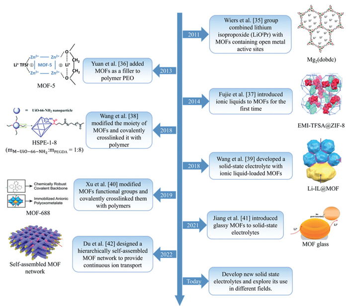
In the last few years, there has been a significant increase in research on MOF-based solid-state electrolytes. Fig. 1 shows a brief history of the development of MOF-based solid-state electrolytes [35–42]. Based on this, this review provides a comprehensive and systematic review of the relevant studies in the field. Here, MOF-based solid-state electrolytes are categorized into three primary types according to the ion-transport mechanism: (1) Pristine MOF-based electrolytes, (2) MOF/ionic-liquid hybrid electrolytes, and (3) MOF/polymer composite electrolytes. Consequently, this review systematically discusses the preparation methods and ion transport mechanisms of three different types of MOF-based solid-state electrolytes. Finally, we provide an outlook towards the development of high-performance MOF-based solid-state electrolytes for high-energy lithium metal batteries.
Figure 1
Figure 1.
A brief history of the development of MOF-based solid-state electrolytes. Reprinted with permission [35]. Copyright 2011, American Chemical Society. Reprinted with permission [36]. Copyright 2013, Elsevier. Reprinted with permission [37]. Copyright 2014, Wiley. Reprinted with permission [38]. Copyright 2018, Royal Society of Chemistry. Reprinted with permission [39]. Copyright 2018, Wiley. Reprinted with permission [40]. Copyright 2019, American Chemical Society. Reprinted with permission [41]. Copyright 2021, Wiley. Reprinted with permission [42]. Copyright 2022, Wiley.
The unique structural framework and exceptional tunability of MOFs make them ideal candidates for engineering lithium–ion transport pathways, which is an essential feature for applications in solid–state electrolytes. To construct lithium-ion transport pathway in MOFs, two strategies have been developed to immobilize anions of lithium salts on MOF frameworks: (1) Binding anions to coordinatively unsaturated metal sites (also known as open metal sites) in MOFs; (2) Linking negatively charged species in MOFs (also known as anionic MOFs) [2,6,43]. Upon the uptake or ion exchange of lithium salts, pristine MOF-based electrolytes can be prepared (see summarized details in Table 1).
Table 1
Table 1.
A summary of representative pristine MOF-based electrolytes.
Upon the uptake of lithium salts into MOFs, open metal sites of MOFs are able to serve as Lewis acid and active sites for binding anions, promoting the dissociation of lithium salts [44,45]. These active sites allow lithium ions to diffuse while inhibiting undesirable diffusion of salt anions, achieving good ionic conductivity and high lithium-ion transference number.
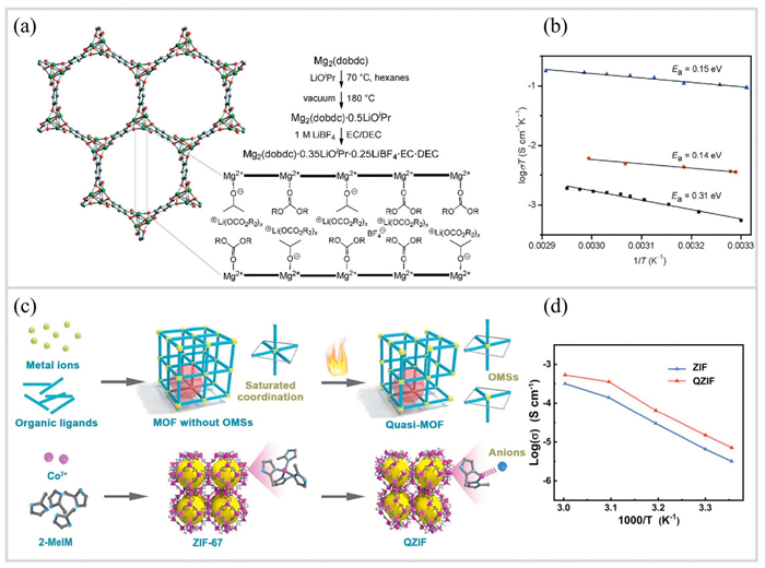
The utilization of open metal sites of MOFs for lithium-ion transport in solid-state electrolytes was first investigated by Wiers et al. [35]. By introducing lithium isopropoxide(LiOiPr) into Mg2(dobdc) (a MOF with open metal sites) and subsequently impregnating in a typical electrolyte (1 mol/L Lithium tetrafluoroborate in ethylene carbonate/diethyl carbonate), they successfully synthesized a solid-state electrolyte with a high ionic conductivity of 3.1 × 10⁻⁴ S/cm at 300 K and a low activation energy of 0.15 eV (Figs. 2a and b). Since then, many studies have been reported using open metal sites of MOFs to promote the dissociation of lithium salt ions to realize fast lithium-ion transport (Table 1).
Figure 2
Figure 2.
(a) The crystal structure of Mg2(dobdc) and synthetic scheme of Mg2(dobdc)-based solid-state electrolytes. Lower right: schematic illustration of lithium salts arranged in the channels of Mg2(dobdc). (b) The Arrhenius plots of Mg2(dobdc)-based electrolytes with different uptake of liquid electrolytes, including Mg2(dobdc)·0.05LiBF4·xEC/DEC (black), Mg2(dobdc)·0.35LiOiPr·0.25LiBF4·EC·DEC (blue), and Mg2(dobdc)·0.06LiOiPr·xEC/DC (red). Reprinted with permission [35]. Copyright 2011, American Chemical Society. (c) Design routes of quasi-MOFs with metal sites and synthetic routes of quasi-ZIF (QZIF). (d) Arrhenius plots of ZIF- and QZIF-based electrolytes. Reprinted with permission [47]. Copyright 2025, Wiley.
However, only a few MOFs with open metal sites have been reported, which limits the selection of MOFs for solid state electrolytes. Interestingly, heating MOFs can create defects for those without open metal sites, leading to the formation of open metal sites [46]. Recently, Xu et al. [47] reported that external heat energy can break part of the coordination bonds of MOFs (Fig. 2c), which induces the formation of open metal sites. This study transforms MOFs lacking open metal sites into quasi-MOFs with open metal sites. After uptake lithium salt, the obtained MOF electrolyte shows an ionic conductivity of 5.4 × 10⁻⁴ S/cm (Fig. 2d). Besides, the symmetric Li||Li cell with this electrolyte can operate stably for > 3000 h at 0.3 mA/cm2, and the Li||LiFePO4 cell shows a capacity retention rate of 85% after 1500 cycles at 1 C.
2.2
Anionic MOFs
In addition to MOFs with open metal sites, anionic MOFs can also provide lithium-ion transport pathway by integrating negatively charged species on MOF frameworks, followed by ion exchange with lithium salts [48–51]. Such negatively charged species can be introduced on either metal nodes (e.g., polyoxometalates) or ligands (e.g., -SO3H). Given that anions are totally immobilized on the MOF frameworks, anionic MOF-based solid-state electrolytes demonstrate high lithium-ion transference number, even forming a single-ion conducting electrolyte [52].
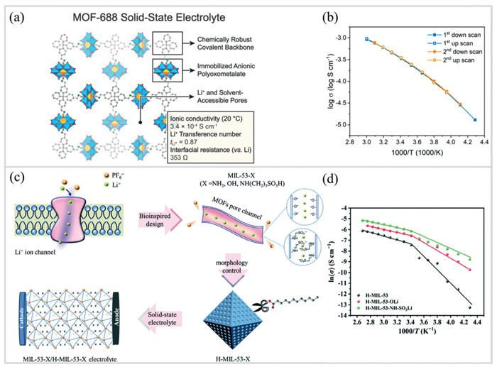
Xu et al. [40] reported a novel three-dimensional anionic MOF-688 with the negatively charged species of molybdenum polyoxometalates for solid-state electrolytes (Fig. 3a). They found that tetrabutylammonium cations in MOF-688 pores could be exchanged with lithium ions, achieving a high ionic conductivity of 3.4 × 10⁻⁴ S/cm at 20 ℃, a high lithium-ion transference number of 0.87, and a low interfacial impedance (353 Ω) (Fig. 3b). A prototype lithium metal battery constructed using this MOF-688 electrolyte operates stably over 200 cycles at ~0.2 C at room temperature (Table 1).
Figure 3
Figure 3.
(a) The crystal structure and structural characteristics of MOF-688, along with key performance of MOF-688 solid-state electrolytes, including ionic conductivity, lithium-ion transference number, and interfacial impedance. (b) The Arrhenius plots of MOF-688 solid-state electrolytes. Reprinted with permission [40]. Copyright 2019, American Chemical Society. (c) Schematic design of MIL-53-X (i.e., H-MIL-53-X) solid-state electrolytes (X = NH2, OH, NH(CH2)3SO3H). MIL-53-X is subjected to ion exchange with lithium salts, enabling the substitution of H+ on functional groups with Li+ to form Li+-conducting channels. (d) Arrhenius plots of different H-MIL-53-X based solid-state electrolyte. Reprinted with permission [51]. Copyright 2025, Wiley.
Besides, anions can be introduced on the ligands by combining functional groups onto MOFs. Wang et al. [51] proposed a biomimetic ion channel-designed MOF to enhance lithium-ion conduction in solid-state electrolytes (Fig. 3c). Inspired by the Na+/K+ conduction mechanism in biological systems, this study mimicked the anion repulsion effect of biological ion channels by incorporating functional groups (e.g., -NH2, -OH, -NH(CH2)3SO3H) into MIL-53-X, thereby improving lithium-ion transference number. The sulfonic acid-modified H-MIL-53-NH-SO3Li exhibits an ionic conductivity of 2.2 × 10⁻³ S/cm and a lithium-ion transference number of 0.78 at 25 ℃, even maintaining a decent conductivity of 10–4 S/cm at −40 ℃ (Fig. 3d). The Li||LiFePO4 cell maintains a discharge capacity of 128.9 mAh/g after 120 cycles at 0.1 C, with a capacity retention rate of about 92% (Table 1).
Owing to their tunability, MOFs have demonstrated a broad scope of material selection for solid-state electrolytes, thereby attracting substantial research interest. However, the compatibility of MOFs with lithium metal and high-voltage cathodes remains a great challenge [39]. For instance, organic ligands and metal centers of MOFs can participate in redox reactions during battery cycling, leading to MOF structural instability and potential battery failure.
3.
MOF/ionic-liquid hybrid electrolytes
Over recent decades, ionic liquids (ILs) have been widely investigated as novel additives to liquid electrolytes and solid polymer electrolytes for lithium metal batteries [53–55], owing to their outstanding properties such as negligible vapor pressure, high-temperature stability, and large electrochemical stability window. However, both anions and cations can migrate in the ionic liquids, leading to low ion transference number and thus poor cycling performance of the cells [56]. Considering the highly porous structure and abundant active sites, MOFs are expected to serve as host materials for immobilizing ionic liquids to enhance the lithium-ion transference number, forming MOF/ionic-liquid hybrid electrolytes (see summarized details in Table 2). Combining ionic liquids with MOFs is usually done in two ways: (1) Filling ionic liquids into the pores of MOFs (i.e., ionic liquid-uptake MOFs); (2) Wetting the surface of MOFs by ionic liquids to promote interparticle diffusion of lithium ions (i.e., ionic liquid-wetted MOFs).
Table 2
Table 2.
A summary of representative MOF/ionic-liquid hybrid electrolytes.
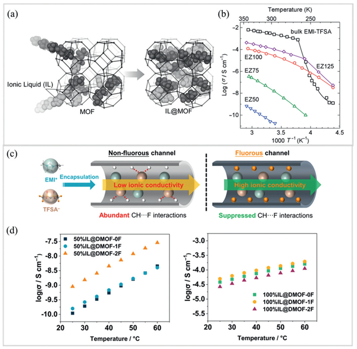
After uptake of ionic liquids, MOF-based electrolytes demonstrate high ionic conductivity. Fujie et al. [37] first reported that an ionic liquid of 1-ethyl-3-methylimidazolium bis(trifluoromethylsulfonyl)amine (EMI-TFSA) was introduced into a zeolite MOF of ZIF-8 (Fig. 4a). This ZIF-8 electrolyte shows a high ionic conductivity of 2.09 × 10⁻⁴ S/cm at 25 ℃ (Fig. 4b) [57]. More interestingly, bulk EMI-TFSA and the EMI-TFSA@ZIF-8 at a pore volume occupancy of 125% (EZ125) exhibite a sharp drop in ionic conductivity at 264 K and 257 K, respectively. In contrast, the EMI-TFSA@ZIF-8 at 50%, 75%, and 100% pore volume occupancies (EZ50, EZ75, EZ100) show no obvious drop in ionic conductivity. Thus, it can be inferred that EMI-TFSA confined in ZIF-8 remains liquid state at temperatures as low as 123 K, whereas the bulk-phase EMI-TFSA freezes at 231 K. This abnormal phase transition behavior is attributed to the "confinement effect" of MOF nanopores on ionic liquids.
Figure 4
Figure 4.
(a) Schematic illustration of the process of ionic liquid (EMI-TFSA) incorporated within the micropores of ZIF-8. Reprinted with permission [37]. Copyright 2014, Elsevier. (b) Arrhenius plots for ZIF-based solid state electrolytes with the volume occupancy ratio of EMI-TFSA to ZIF-8 pores. The EZ50 (blue), EZ75 (green), EZ100 (red), and EZ125 (purple) refer to the volume ratios of EMI-TFSA to the pore volume of ZIF-8 at 50%, 75%, 100%, and 125%, respectively. Reprinted with permission [57]. Copyright 2016, Elsevier. (c) Schematic diagram of ion transport in non-fluorous channel (left) and fluorous channel (right) with encapsulated ionic liquids. (d) Arrhenius plots of three Zn-based MOF electrolytes (DMOF-0F, DMOF-1F, DMOF-2F with different content of fluorous ligands) filled with ionic liquid at pore volume occupancy of 50% (left) and 100% (right). Reprinted with permission [62]. Copyright 2025, American Chemical Society.
The strategy of simply encapsulating the ionic liquid in a MOF channel has limited improvement in ionic conductivity and lithium-ion transference number. To further improve the performance, some studies have started to modify MOF hosts [55,58–61]. For example, Di et al. [62] pioneered ligand fluorination of MOFs for uptake of ionic liquids, leading to enhanced ionic conductivity. In this study, EMI-TFSI was introduced into three isostructural zinc-based microporous MOFs (Zn2(xFBDC)(tmBDC)(DABCO) (hereafter DMOF-xFs), where x denotes the amount of fluorine on the terephthalate ligands (xFBDC2−; x = 0, 1, and 2) with or without ligand fluorination (Fig. 4c). The fluorinated MOF electrolyte shows a high ionic conductivity of 4.3 × 10⁻⁴ S/cm, which is an order of magnitude higher than those of the non-fluorinated MOF electrolytes (2.7 × 10⁻⁵ S/cm) (Fig. 4d).
Tuning the microstructure of MOFs is another effective approach to enhance ionic conductivity of MOF/ionic-liquid hybrid electrolytes, since the pore size of MOFs serves as a critical factor limiting ionic transport. Wu et al. [63] reported UiO-66 for the uptake of ionic liquids by physical adsorption. This UiO-66 electrolyte shows a high ionic conductivity of 3.2 × 10⁻⁴ S/cm and a lithium-ion transference number of 0.33 at 25 ℃ (Table 2). Notably, Li||Li symmetric cells using this UiO-66 electrolyte exhibit an interfacial resistance of 12 Ω cm2 after 100 cycles at 200 µA/cm2 and 60 ℃, demonstrating excellent interfacial contact with the metallic lithium anode. The Li||LiFePO4 batteries using this electrolyte exhibit a high discharge capacity of 130 mAh/g at 1 C, with a high retention rate of 94% after 380 cycles (Table 2).
3.2
Ionic liquid-wetted MOFs
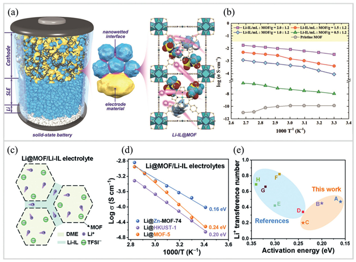
In addition to the uptake of ionic liquids within the MOF pores, the ionic liquids can also have an interfacial wetting effect to provide interparticle diffusion pathway. The effect of ionic liquid wetting on interfacial ionic conductivity was first investigated by Wang et al. [39], in which they developed solid-like electrolytes with nano-wetting interfaces by impregnating ionic liquids in MOF-525 nanocrystals (Fig. 5a). This MOF-525 electrolyte exhibits a high ionic conductivity of 3.0 × 10⁻⁴ S/cm at room temperature (Fig. 5b), a lithium-ion transference number of 0.36, and good interfacial compatibility with both electrodes (Table 2). Benefiting from three-dimensional lithium-ion conductive network via enhanced interfacial wettability, the Li||LiFePO4 solid-state battery with a high loading of active material (25 mg/cm2) demonstrates a high capacity of 132 mAh/g with a retention rate of 91% for 100 cycles in the wide temperature range from −20 ℃ to 150 ℃.
Figure 5
Figure 5.
(a) Schematic illustration of a solid-state battery using the ionic liquid-wetted MOF electrolyte (Li-IL@MOF-525), with an enlarged view of the MOF crystal structure and randomly distributed [EMIM]+ and [TFSI]− ions within the pores (pink spheres represent Li+ ions). (b) Arrhenius plots of Li-IL@MOF solid-state electrolytes with different loading of ionic liquid. Reprinted with permission [39]. Copyright 2018, Wiley. (c) Schematic illustration of ion transport in ionic liquid-wetted MOF electrolyte. (d) Arrhenius plots of ionic liquid-wetted MOF electrolytes using three different MOFs. (e) Comparison of lithium-ion transference number and activation energy of this work with other studies (sample A, B, and C refer to Li@Zn-MOF-74/Li-IL, Li@HKUST-1/Li-IL, and Li@MOF-5/Li-IL, respectively). Reprinted with permission [64]. Copyright 2023, Wiley.
Since then, the use of ionic liquids as binder to provide interfacial wetting become popular for MOF-based solid electrolytes. Our group synthesized a series of MOF nanoparticles with different open metal sites and pore structures [64]. After the uptake of lithium salt, the MOF nanoparticles were mixed with ionic liquid as a binder to prepare solid state electrolyte (Fig. 5c). The ionic liquid not only holds the nanoparticles together but also forms ion transport pathways. As a results, the Li@Zn-MOF-74/Li-IL electrolyte exhibits a high ionic conductivity of 1.5 × 10⁻⁴ S/cm and lithium-ion transference number of 0.47 at 30 ℃ (Figs. 5d and e). The Li||LiFePO4 cell assembled with this electrolyte shows a capacity retention rate of 90% after 500 cycles at 0.5 C (Table 2).
4.
MOF/polymer composite electrolytes
Composite polymer electrolytes are very promising for applications in solid-state batteries due to their great flexibility, ease of preparation, and low cost. MOFs with open metal sites or functional organic linkers show great potential as active fillers for polymer electrolytes, which enhances the structural strength, ionic conductivity, and lithium-ion transference number of composite polymer electrolytes [65–67]. Compositing MOFs with polymer electrolytes forms MOF/polymer composite electrolytes, which have been widely studied (see summarized details in Table 3). This section categorizes them into three types: (1) Direct blending of MOFs fillers into polymer electrolytes; (2) MOFs grown on nanofibers as filler of polymer electrolytes; (3) Covalent cross-linking of MOFs with polymer electrolytes.
Table 3
Table 3.
A summary of representative MOF/polymer composite electrolytes.
4.1
Direct blending of MOFs into polymer electrolytes
Solid-state polymer electrolytes using poly(ethylene oxide) (PEO) have attracted much attention because of their high lithium-ion solvation capability, great lithium anode compatibility, and good flexibility. As a result, MOFs as fillers in PEO-based polymer electrolytes have been widely studied [33,68–71]. Besides, other polymer electrolytes such as PVDF have also been developed [27,66,72,73]. In general, the integration of MOFs with polymers represents a highly promising research direction.
Blending MOFs directly into PEO-based polymer electrolytes was first reported by Yuan et al. [36], in which they introduced MOF-5 as nanofiller into PEO-based polymer electrolytes. Benefiting from the interactions of Zn2+ sites of MOF-5 with lithium salt and PEO chains (Fig. 6a), the MOF-5/PEO composite electrolyte shows a decent ionic conductivity of 3.16 × 10⁻⁵ S/cm at 25 ℃ (Fig. 6b). This study opens up the door of MOFs as fillers for polymer electrolytes.
Figure 6
Figure 6.
(a) Schematic illustration of enhanced ionic conductivity of solid polymer electrolytes using MOF-5 as filler. Lewis acid sites on MOF-5 interact with PEO chains and lithium salts to promote lithium salt dissociation (upper part). MOF-5 provides additional conductive channels for ion transport (lower part). (b) Arrhenius plots for the ionic conductivity of different MOF content (0%, 10%) and different PEO: Li ratios (6:1, 10:1, 16:1, 25:1, 30:1). Reprinted with permission [36]. Copyright 2013, Elsevier. (c) Schematic illustration of lithium deposition in PEO-based solid-state electrolyte and anion-immobilized P@CMOF solid-state electrolyte (with grafted -NH2 groups for anion immobilization via electrostatic interactions). (d) Lithium-ion transference number of P@CMOF electrolyte. Reprinted with permission [68]. Copyright 2019, Elsevier. (e) Schematic illustration of weak-bonded lithium-ion transport networks within composite polymer electrolytes (CIL-MOF/PVDF). (f) Arrhenius plots for the ionic conductivity for three different solid polymer electrolytes. Reprinted with permission [73]. Copyright 2025, Wiley.
To enhance the lithium-ion transference number, MOF fillers can be designed to immobilize the salt anions by open metal sites or functional ligands. Huo et al. [68] proposed the use of cationic MOFs as fillers to immobilize the salt anions, leading to a high lithium-ion transference number of 0.72 and the ionic conductivity of 6.3 × 10⁻⁴ S/cm (Figs. 6c and d). As a result, the Li||Li symmetric cell with this MOF electrolyte can be operated stably for 200 h at 0.5 mA/cm2. The Li||LiFePO4 full cell shows an initial discharge capacity of 135.1 mAh/g at 0.1 C, with a capacity retention rate of 85.4% after 300 cycles (Table 3).
To achieve high ionic conductivity of such composite polymer electrolytes, Gao et al. [73] reported a new polymer electrolyte based on a weakly bonded lithium-ion transport network. The synergistic interaction of ionic liquids and MOFs promotes the dissociation of lithium salts, generating more free lithium ions (Fig. 6e). As a result, this MOF electrolyte achieves a high ionic conductivity of 1.14 × 10⁻³ S/cm at 30 ℃ and a wide electrochemical window of 4.82 V (Fig. 6f).
While directly blending MOF nanoparticles into polymer matrix is a convenient approach, this method often suffers from uneven dispersion of MOF fillers due to the agglomeration of MOF nanoparticles. Such agglomeration compromises the ionic conductivity of electrolytes, which needs further studies.
4.2
MOFs grown on nanofibers as filler of polymer electrolytes
To solve the problem of the uneven dispersion of MOF nanoparticles in polymer electrolytes, a strategy of growing MOFs on nanofibers has been proposed [42,74,75], achieving an homogenous mix.
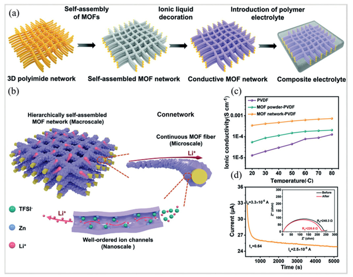
Du et al. [42] constructed a continuous lithium-ion transport pathway by growing MOF nanocrystals on a one-dimensional polyimide fiber (Figs. 7a and b). The composite electrolyte shows a high ionic conductivity of 4.08 × 10⁻⁴ S/cm at 30 ℃ and a high lithium-ion transference number of 0.64, as well as a good mechanical strength of 22.0 MPa (Figs. 7c and d). As a result, the Li||LiFePO4 cell shows a high capacity of 152.6 mAh/g at 0.5 C rate with a capacity retention of 96% after 500 cycles (Table 3).
Figure 7
Figure 7.
(a) Fabrication process of polymer solid-state electrolytes based on hierarchically self-assembled MOF networks. (b) Schematic diagram of hierarchically self-assembled MOF networks. (c) Temperature-dependent ionic conductivities of different solid electrolytes. (d) Lithium-ion transference number measurement for the MOF network-PVDF composite solid electrolyte. Reprinted with permission [42]. Copyright 2022, Wiley.
Similarly, Xu et al. [76] constructed a zirconium-based MOF-808 three-dimensional network by electrostatic spinning of MOF and polyacrylonitrile (PAN), which was used as filler for PEO-based solid polymer electrolyte to form a uniformly dispersed composite electrolyte (MOF808@PAN@PEO-LiTFSI). The 3D-structured ion transport network in this MOF electrolyte not only effectively promotes Li+ transport, but also inhibits the growth of lithium dendrites. As a result, this MOF electrolyte shows a lithium-ion transference number of 0.42 and an ionic conductivity of 2.83 × 10⁻⁵ S/cm. Moreover, the Li||LiFePO4 full cell using this MOF electrolyte shows a stable electrode-electrolyte interface, achieving a capacity retention rate of 77% and an average coulombic efficiency of 99.9% after 1000 cycles at 1 C.
The in-situ growth of MOFs on nanofibers mitigates the agglomeration of MOF particles and thus improves the ionic conductivity by forming a continuous ionic transport pathway.
4.3
Covalent cross-linking of MOFs with polymer electrolytes
To further reduce the agglomeration of MOF particles in composite electrolytes, a few studies report covalent cross-linking of MOFs with polymer chains [38,77–81].
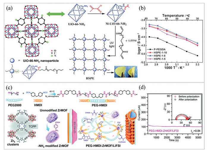
Covalent cross-linking was first applied to MOF/polymer composite electrolytes by Wang et al. [38]. In the work, vinyl-functionalized MOF (M-UIO-66-NH2) nanoparticles were covalently cross-linked with poly(ethylene glycol) diacrylate (PEGDA) by UV-initiated polymerization, leading to a flexible self-supported hybrid polymer electrolytes (Fig. 8a). Benefiting from the three-dimensional lithium-ion transport network, this cross-linked electrolyte shows an ionic conductivity of 4.31 × 10⁻⁵ S/cm at 30 ℃ (Fig. 8b), representing a 5-fold enhancement compared to MOF-free polymer electrolytes (Table 3).
Figure 8
Figure 8.
(a) Synthetic route of the covalently cross-linked MOF electrolyte (HSPEs). (b) The ionic conductivity of HSPEs and poly(ethylene glycol) diacrylate (PEGDA) electrolyte. Reprinted with permission [38]. Copyright 2018, Wiley. (c) Schematic for the preparation of multisite crosslinked poly(ether-urethane)-based polymer electrolytes (PEG-HMDI-ZrMOF/LiFSI). (d) Lithium-ion transference number measurement for the PEG-HMDI-ZrMOF/LiFSI electrolyte. Reprinted with permission [80]. Copyright 2024, Wiley.
Similarly, Wang et al. [78] fabricated a MOF-based cross-linked electrolytes and emphasized mechanistic-electrochemical synergistic optimization. In this work, vinyl-functionalized MOF (UIO-66-NH-MET) nanoparticles were covalently cross-linked with tetrakis(3-mercaptopropionic acid) pentaerythritol (PETMP) and PEGDA via C-S-C bonds (Fig. 8c). This cross-linked electrolyte shows an ionic conductivity of 2.26 × 10⁻⁴ S/cm at 30 ℃ (Fig. 8d). As a result, the Li||Li symmetric cell assembled with this electrolyte cycled stably for 1300 h, and the Li||LiFePO4 full cell cycled 500 times at 0.5 C with a capacity retention of 85.6% (Table 3).
Pei et al. [80] investigated the compatibility of MOF-based cross-linked electrolytes with high-voltage cathodes. As shown in Fig. 8c, amino-modified Zr-porphyrin MOF (Zr-MOF) nanoparticles were covalently cross-linked with 4,4′-methylenebis(cyclohexyl isocyanate) (HMDI) and poly(ethylene glycol) (PEG). The cross-linked MOF electrolyte shows a high Li+ conductivity of 5.7 × 10⁻⁴ S/cm and lithium-ion transference number of 0.84 at 30 ℃ (Fig. 8d). Benefiting from the electron-withdrawing groups of HMDI matrix and excellent stability of Zr-MOF, the cross-linked MOF electrolyte shows a high electrochemical oxidation stability of 5.1 V, enabling the compatibility with high-voltage cathodes.
MOFs and polymers are covalently bonded to form highly stable composite structures. This covalent cross-linking not only enhances interfacial adhesion between MOFs and polymers but also constructs ion transport pathways, demonstrating great potentials for composite polymer electrolytes.
5.
Other types of MOF-based solid electrolytes
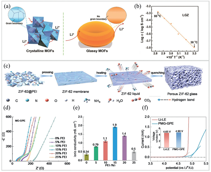
Recently, a new category of MOF-based solid-state electrolytes based on MOF glass have been emerged. In general, glassy MOF is formed by heating and melting, followed by rapid quenching. Such glassy MOFs feature the absence of grain boundaries, which minimizes hindrance to ion transport and thus achieving high ionic conductivity of electrolytes (see summarized details in Table 4) [82–87].
Table 4
Table 4.
A summary of representative other types of MOF-based solid electrolytes.
Jiang et al. [41] pioneered the use of glassy ZIF-4 for quasi-solid-state electrolytes (LGZ). Specifically, ZIF-4 crystals were heated from room temperature to 580 ℃ and then rapidly cooled under nitrogen atmosphere, leading to the glassy ZIF-4 (Fig. 9a). By overcoming ion transport limitations imposed by grain boundaries in crystalline MOFs, the glassy LGZ electrolytes achieves a high ionic conductivity of 1.61 × 10⁻⁴ S/cm at 30 ℃ (Fig. 9b). Moreover, the Li||LiFePO4 cell using LGZ electrolyte shows a high initial capacity of 101.2 mAh/g at 1 C with a high capacity retention rate of 100% after 500 cycles (Table 4).
Figure 9
Figure 9.
(a) Schematic illustration of lithium-ion conduction in crystalline and glassy MOFs, in which glassy MOF lacks grain boundaries that are inherent in crystalline MOF and often impede ion transport. (b) Temperature-dependent conductivity plot of a glassy MOF electrolyte (LGZ). Reprinted with permission [41]. Copyright 2021, Wiley. (c) Schematic illustration of the fabrication of free-standing porous glassy ZIF-62 membranes with 3D interconnected gradient pores for fast ion transport. (d) Electrochemical impedance and (e) ionic conductivity of different glassy MOF electrolytes. (f) Linear scan voltammetry curves and electrochemical oxidation stability of glassy MOF electrolytes. Reprinted with permission [83]. Copyright 2024, Wiley.
Concurrently, Xiang et al. [83] introduced a top-down strategy to fabricate porous MOF glass/gel polymer electrolytes (PMG-GPEs). In this study, a three-dimensional interconnected hierarchical porous network was precisely engineered via the polymer templating method (Fig. 9c). The macropores act as "bridges" to accelerate bulk ion transport, while the micropores and mesopores immobilize anions through the nano-confinement effect, achieving a high ionic conductivity of 1.9 mS/cm and a lithium-ion transference of 0.70 (Figs. 9d and e). In addition, the oxidation window of the electrolyte is significantly increased (Fig. 9f). The Li||LiFePO4 using PMG-GPE electrolyte still shows a capacity retention of 83% after 1400 cycles at 1 C.
6.
Conclusions and perspectives
In summary, we have discussed in this review the recent research progress of metal-organic framework-based solid-state electrolytes, presenting the structural compositions and related performance characteristics of three primary types of MOFs-based solid-state electrolytes. First, we discuss the ionic conduction mechanism of pristine MOFs as lithium-ion conductors, where MOFs with open metal sites and anionic MOFs have the potential for high Li-ion transference numbers. Second, the introduction of nonflammable ionic liquids improves the interfacial wettability of MOF-based solid electrolytes, while the unique properties of ionic liquids bring about a wider electrochemical and temperature operating window of solid electrolytes. Third, combining MOFs with polymers is one of the mainstream directions of current research. Here, the interaction between MOFs open metal sites and polymer chains enhances the mechanical strength of polymers, while the interaction between open metal sites and lithium salts promotes salt dissociation and thus the increase of ionic conductivity. Additionally, MOF glasses are discussed as other types of MOF-based solid-state electrolytes.
Although MOFs-based solid-state electrolytes exhibit many advantages, there are still some challenges that need to be addressed. In future, the following aspects need to be improved:
(1) Pristine MOF-based electrolytes usually have high ion transference numbers and decent ionic conductivity, but their weak mechanical strength makes it difficult to suppress the dendrite problem in lithium-metal batteries. The structural design of pristine MOF-based electrolytes is suggested to improve mechanical strength, such as the design of framework topology and the functionalization of organic ligands.
(2) The introduction of ionic liquids improves the performance of solid-state electrolytes, but both cation and anion of ionic liquids migrate, which leads to a low Li-ion transference number of the electrolyte and reduces the energy efficiency of the battery. Therefore, how to limit the anion migration has become the core of the research direction of this type of electrolyte.
(3) Combining MOFs with polymers can improve mechanical properties and ionic conductivity of MOF-based solid electrolytes. However, MOF fillers are often difficult to disperse homogeneously in polymer matrix, which prevents the formation of conductive percolation networks and thus leads to low ionic conductivity. In fact, there have been considerable research attempts to solve the problem of dispersion of MOF fillers, such as in situ growth and covalent cross-linking. There is still room for advancing the performance of such MOF/polymer composite electrolytes. Therefore, further exploration of how to uniformly disperse MOFs in polymer matrix remains a research priority for this type of electrolyte.
MOFs-based solid-state electrolytes have been shown to have great potential for development in the field of solid-state batteries. In future, we encourage the development of new types of MOFs-based solid-state electrolytes, such as glassy MOFs, two-dimensional MOFs, and high-entropy MOFs. Besides, experimental analysis in combination with computational techniques (e.g., firs-principles calculations and molecular dynamics simulation) helps us to fundamentally understand the ion transport mechanism of MOF electrolytes, which guides the rational design of MOF structures for solid-state electrolytes. In addition, the large-scale production of MOF-based solid-state electrolytes will become a future research hotspot, which will also bring up the critical issue of recycling spent solid-state batteries. Therefore, it is needed to study the recycling of MOF-based solid-state electrolytes in the near future, which not only mitigates the environmental impact of transition metals but also offers significant economic benefits.
CRediT authorship contribution statement
Xin Xia: Writing – original draft. Zhong-Qi Zhang: Writing – original draft. Qing Wen: Resources. Pei-Yao Li: Formal analysis. Ding-Hao Le: Methodology. Zhen-Yu Wang: Writing – original draft. Pan-Pan Dong: Data curation. Guo-Dong Ren: Formal analysis. Jun-Chao Zheng: Supervision.
Declaration of competing interest
The authors declare that they have no known competing financial interests or personal relationships that could have appeared to influence the work reported in this paper.
Acknowledgments
We gratefully acknowledge the financial support from National Natural Science Foundation of China (No. 52272261), the Science and Technology Innovation Program of Hunan Province (No. 2024RC1021), Department of Education of Hunan Province of China (No. 23B0020), Sichuan Science and Technology Program (No. 2025ZNSFSC1413) and the Science and Technology Program of ChangSha City (No. Kq2402211).
[1]
C. Yang, K. Fu, Y. Zhang, et al., Adv. Mater. 29 (2017) 1701169. doi: 10.1002/adma.201701169
Y. Xiang, N. Yu, J. Li, et al., Angew. Chem. Int. Ed. 64 (2025) e202424288. doi: 10.1002/anie.202424288
[84]
J. Ding, T. Du, L.R. Jensen, et al., Adv. Mater. 36 (2024) 2400652. doi: 10.1002/adma.202400652
[85]
J. Ding, T. Du, E.H. Thomsen, et al., Adv. Sci. 11 (2024) 2306698. doi: 10.1002/advs.202306698
[86]
O. Kong, G. Jiang, K. Wang, et al., Adv. Energy Mater. 15 (2025) 2405593. doi: 10.1002/aenm.202405593
[87]
R. Gaillac, P. Pullumbi, K.A. Beyer, et al., Nat. Mater. 16 (2017) 1149–1154. doi: 10.1038/nmat4998
Figure 1
A brief history of the development of MOF-based solid-state electrolytes. Reprinted with permission [35]. Copyright 2011, American Chemical Society. Reprinted with permission [36]. Copyright 2013, Elsevier. Reprinted with permission [37]. Copyright 2014, Wiley. Reprinted with permission [38]. Copyright 2018, Royal Society of Chemistry. Reprinted with permission [39]. Copyright 2018, Wiley. Reprinted with permission [40]. Copyright 2019, American Chemical Society. Reprinted with permission [41]. Copyright 2021, Wiley. Reprinted with permission [42]. Copyright 2022, Wiley.
Figure 2
(a) The crystal structure of Mg2(dobdc) and synthetic scheme of Mg2(dobdc)-based solid-state electrolytes. Lower right: schematic illustration of lithium salts arranged in the channels of Mg2(dobdc). (b) The Arrhenius plots of Mg2(dobdc)-based electrolytes with different uptake of liquid electrolytes, including Mg2(dobdc)·0.05LiBF4·xEC/DEC (black), Mg2(dobdc)·0.35LiOiPr·0.25LiBF4·EC·DEC (blue), and Mg2(dobdc)·0.06LiOiPr·xEC/DC (red). Reprinted with permission [35]. Copyright 2011, American Chemical Society. (c) Design routes of quasi-MOFs with metal sites and synthetic routes of quasi-ZIF (QZIF). (d) Arrhenius plots of ZIF- and QZIF-based electrolytes. Reprinted with permission [47]. Copyright 2025, Wiley.
Figure 3
(a) The crystal structure and structural characteristics of MOF-688, along with key performance of MOF-688 solid-state electrolytes, including ionic conductivity, lithium-ion transference number, and interfacial impedance. (b) The Arrhenius plots of MOF-688 solid-state electrolytes. Reprinted with permission [40]. Copyright 2019, American Chemical Society. (c) Schematic design of MIL-53-X (i.e., H-MIL-53-X) solid-state electrolytes (X = NH2, OH, NH(CH2)3SO3H). MIL-53-X is subjected to ion exchange with lithium salts, enabling the substitution of H+ on functional groups with Li+ to form Li+-conducting channels. (d) Arrhenius plots of different H-MIL-53-X based solid-state electrolyte. Reprinted with permission [51]. Copyright 2025, Wiley.
Figure 4
(a) Schematic illustration of the process of ionic liquid (EMI-TFSA) incorporated within the micropores of ZIF-8. Reprinted with permission [37]. Copyright 2014, Elsevier. (b) Arrhenius plots for ZIF-based solid state electrolytes with the volume occupancy ratio of EMI-TFSA to ZIF-8 pores. The EZ50 (blue), EZ75 (green), EZ100 (red), and EZ125 (purple) refer to the volume ratios of EMI-TFSA to the pore volume of ZIF-8 at 50%, 75%, 100%, and 125%, respectively. Reprinted with permission [57]. Copyright 2016, Elsevier. (c) Schematic diagram of ion transport in non-fluorous channel (left) and fluorous channel (right) with encapsulated ionic liquids. (d) Arrhenius plots of three Zn-based MOF electrolytes (DMOF-0F, DMOF-1F, DMOF-2F with different content of fluorous ligands) filled with ionic liquid at pore volume occupancy of 50% (left) and 100% (right). Reprinted with permission [62]. Copyright 2025, American Chemical Society.
Figure 5
(a) Schematic illustration of a solid-state battery using the ionic liquid-wetted MOF electrolyte (Li-IL@MOF-525), with an enlarged view of the MOF crystal structure and randomly distributed [EMIM]+ and [TFSI]− ions within the pores (pink spheres represent Li+ ions). (b) Arrhenius plots of Li-IL@MOF solid-state electrolytes with different loading of ionic liquid. Reprinted with permission [39]. Copyright 2018, Wiley. (c) Schematic illustration of ion transport in ionic liquid-wetted MOF electrolyte. (d) Arrhenius plots of ionic liquid-wetted MOF electrolytes using three different MOFs. (e) Comparison of lithium-ion transference number and activation energy of this work with other studies (sample A, B, and C refer to Li@Zn-MOF-74/Li-IL, Li@HKUST-1/Li-IL, and Li@MOF-5/Li-IL, respectively). Reprinted with permission [64]. Copyright 2023, Wiley.
Figure 6
(a) Schematic illustration of enhanced ionic conductivity of solid polymer electrolytes using MOF-5 as filler. Lewis acid sites on MOF-5 interact with PEO chains and lithium salts to promote lithium salt dissociation (upper part). MOF-5 provides additional conductive channels for ion transport (lower part). (b) Arrhenius plots for the ionic conductivity of different MOF content (0%, 10%) and different PEO: Li ratios (6:1, 10:1, 16:1, 25:1, 30:1). Reprinted with permission [36]. Copyright 2013, Elsevier. (c) Schematic illustration of lithium deposition in PEO-based solid-state electrolyte and anion-immobilized P@CMOF solid-state electrolyte (with grafted -NH2 groups for anion immobilization via electrostatic interactions). (d) Lithium-ion transference number of P@CMOF electrolyte. Reprinted with permission [68]. Copyright 2019, Elsevier. (e) Schematic illustration of weak-bonded lithium-ion transport networks within composite polymer electrolytes (CIL-MOF/PVDF). (f) Arrhenius plots for the ionic conductivity for three different solid polymer electrolytes. Reprinted with permission [73]. Copyright 2025, Wiley.
Figure 7
(a) Fabrication process of polymer solid-state electrolytes based on hierarchically self-assembled MOF networks. (b) Schematic diagram of hierarchically self-assembled MOF networks. (c) Temperature-dependent ionic conductivities of different solid electrolytes. (d) Lithium-ion transference number measurement for the MOF network-PVDF composite solid electrolyte. Reprinted with permission [42]. Copyright 2022, Wiley.
Figure 8
(a) Synthetic route of the covalently cross-linked MOF electrolyte (HSPEs). (b) The ionic conductivity of HSPEs and poly(ethylene glycol) diacrylate (PEGDA) electrolyte. Reprinted with permission [38]. Copyright 2018, Wiley. (c) Schematic for the preparation of multisite crosslinked poly(ether-urethane)-based polymer electrolytes (PEG-HMDI-ZrMOF/LiFSI). (d) Lithium-ion transference number measurement for the PEG-HMDI-ZrMOF/LiFSI electrolyte. Reprinted with permission [80]. Copyright 2024, Wiley.
Figure 9
(a) Schematic illustration of lithium-ion conduction in crystalline and glassy MOFs, in which glassy MOF lacks grain boundaries that are inherent in crystalline MOF and often impede ion transport. (b) Temperature-dependent conductivity plot of a glassy MOF electrolyte (LGZ). Reprinted with permission [41]. Copyright 2021, Wiley. (c) Schematic illustration of the fabrication of free-standing porous glassy ZIF-62 membranes with 3D interconnected gradient pores for fast ion transport. (d) Electrochemical impedance and (e) ionic conductivity of different glassy MOF electrolytes. (f) Linear scan voltammetry curves and electrochemical oxidation stability of glassy MOF electrolytes. Reprinted with permission [83]. Copyright 2024, Wiley.


 DownLoad:


 下载:
下载:


 下载:
下载:

