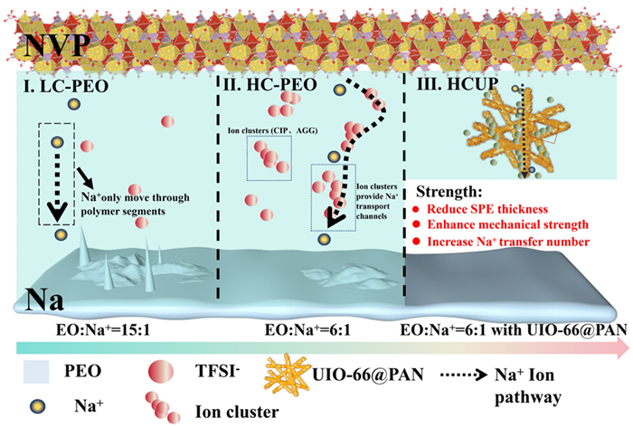
Scheme 1.
Schematic illustration of the Na+ conducting mechanism in the LC-PEO, HC-PEO as well as the HC-PEO/UIO-66@PAN (HCUP) electrolyte.

High-rate Na+ diffusion in solid polymer electrolytes enabled by high-concentration Na salt aggregates and size-selective anion immobilization
Yuxiang Guo , Peiwen Fan , Jiacheng Liu , Qinpeng Qiao , Ahu Shao , Lu Cheng , Jiawen Tang , Yaxin Zhang , Zhiqiao Wang , Yunsong Li , Helin Wang , Chunwei Li , Junyu Zhang , Yue Ma


All-solid-state sodium metal batteries (ASSMBs) have emerged as a transformative alternative to conventional lithium-ion technologies, owing to the natural abundance and low cost of sodium resources, high theoretical capacity of metallic Na anode (1166 mAh/g), as well as inherent operational safety from non-flammable solid-state components [1–6]. Central to the performance of ASSMB lies the solid ionic conductor, where solid polymer electrolytes (SPEs) afford distinct advantages over inorganic ceramics, including superior Na+ solvation capability and compatibility with scalable roll-to-roll manufacturing, a critical requirement for large-scale battery production [7–10]. However, SPEs face intrinsic limitations that hinder their practical deployment: (1) Low ionic conductivity at ambient temperatures (< 10–4 S/cm), arising from sluggish Na+ diffusion kinetics in semi-crystalline polymer matrices [11]; (2) Insufficient cationic transference numbers (tNa+ < 0.5), caused by excessive anion mobility that aggravates interfacial polarization [12]; (3) Inherent mechanical-thermal trade-offs that induce interfacial degradation, such as heterogeneous Na deposition and electrolyte-electrode delamination during galvanostatic operation [13–15].
The ionic conduction in SPEs primarily relies on localized relaxation and segmental motion within amorphous polymer domains [16–19]. However, the high crystallinity of most SPEs at ambient temperatures severely restricts Na+ mobility, resulting in unsatisfactory ionic conductivity (10–6–10–5 S/cm at 25 ℃) [20–22]. To address this limitation, several strategies have been proposed to suppress crystallinity and enhance ion transport. For instance, polymeric engineering techniques such as the cross-linking and copolymerization techniques could enhance chain segment mobility while reinforcing mechanical networks to inhibit dendrite formation [23–26]. However, excessive cross-linking density adversely restricts ion transport dynamics [27]. Moreover, incorporating ionic liquids (e.g., Pyr13TFSI [28], EMI-TFSI [29]) or molecular plasticizers (PC [30], DME [31], SN [32]) might disrupt intermolecular interactions, increasing amorphous phase content. While effective in enhancing conductivity, these additives often compromise mechanical integrity and react severely with the Na foil. Alternatively, CPEs that integrate a polymeric matrix with inorganic fillers (e.g., oxides, sulfides, or hydrides) [33–35], would reduce polymer crystallinity and create additional amorphous regions. However, the practical performance of CPEs is often limited by random dispersed fillers, the agglomeration of which leads to the fragmented ion transport pathways [36]. Recently, the polymer-in-salt solid electrolytes (PISSEs) with high sodium salt concentrations (> 50 wt%) leverage intensive polymer-salt coordination to disrupt crystalline ordering, enabling the synergistic Na+ conduction not only via the segmental motion, but also through the percolating TFSI−-coordinated ion clusters [37]. Despite the improved ionic conductivity, the plasticizing effect of excessive salts severely compromises mechanical integrity (tensile strength < 0.5 MPa), increasing risks of membrane penetration and Na dendrite propagation [38,39]. Despite these advancements, critical challenges persist in the SPE design, requiring simultaneous optimization of: (1) Continuous Na+ transport pathways for rapid ion conduction, (2) enhanced Na+ transference numbers (tNa+) to mitigate concentration polarization, and (3) sufficient mechanical strength to suppress dendrite growth [40], all of which are essential for developing high-performance, high-energy-density ASSMBs.
Beyond intrinsic cation diffusion kinetics, the volumetric and gravimetric energy densities of cell-level prototypes are critically governed by the thickness and areal mass loading of SPEs. Current ASSMB prototypes utilizing SPE membranes require the thickness control over 50 µm and mass loadings above 4 mg/cm2 to ensure mechanical processability, creating a critical dimensional disparity when compared to commercial polyolefin separators in liquid cells (PE: 12–20 µm, 0.6–1.2 mg/cm2) [10,41]. This structural mismatch substantially compromises the theoretical capacity advantages of metallic Na anodes (1166 mAh/g, 1130 Ah/L). Emerging modification strategies infiltrating nanostructured scaffolds within polymer matrix demonstrate effective thickness reduction below 30 µm [42,43]. However, ceramic-based scaffolds exhibit inherent brittleness and poor compatibility with roll-to-roll manufacturing [44,45]. Recent advances thus include innovative approaches of flexible scaffold design: Zhou et al. created a Janus-type PE separator with PMTFSINa electrolyte layers, enhancing interfacial stability via tailored covalent bonding [46]; Wan et al. developed a polyimide (PI)-based CPE featuring vertically aligned channels infused with PEO/LiTFSI, which enhanced ionic conductivity while ensuring intrinsic safety [47]. Hassan et al. pioneered biopolymer-based electrolyte systems using nanostructured electrospun scaffold of cellulose derivatives and chitosan synergistically [48]. While existing CPE technologies struggle to reconcile ultrathin, lightweight designs with sufficient mechanical strength for ASSMB prototyping, the more critical bottleneck lies in metastable anode interfaces. Spatial heterogeneity in Na+ flux distribution exacerbates the CPE/Na foil chemical incompatibility, driving the dendritic formation and Na+ source depletion. Accordingly, recent anion-regulation strategies employ two kinds of alleviation approaches: (1) Steric hindrance via large-anion sodium salts (e.g., BETI− [49], PSS− [4], SO2N(−)SO2CF3 [7]) to immobilize anions and mitigate concentration polarization [50]; and (2) selective anion trapping using nanoporous fillers (MOFs, COFs [51], charged nano clay) or ion-selective interlayers to enhance Na+ transference. These advances necessitate mechanically robust scaffolds that integrate dual functionality, namely the anion confinement and Na+ pathway optimization, while addressing interfacial stability, processability, and ion transport kinetics in sub-30 µm SPEs for ASSMB deployment.
In this study, we presented an ultrathin (25 µm), lightweight (1.76 mg/cm2) CPE membrane through a hetero-phase design strategy to enable the room-temperature cyclability of ASSMBs. The modular CPE design integrates: (1) A high-concentration NaTFSI/PEO matrix (EO: Na+ = 6:1) forms self-assembling Na+-TFSI− cluster networks, creating anion-regulated percolation-type pathways that enable high-rate Na+ transport; and (2) a 3D electrospun PAN scaffold uniformly encapsulating UIO-66 nanoparticles (UIO-66@PAN), where the sub-nanometer-precise UIO-66 architecture (7.5–8.1 Å pore) implements TFSI− sieving (7.9 Å diameter) through steric-electronic confinement. This synergistic interplay endows the CPE with an order-of-magnitude enhancement in mechanical strength (3.46 MPa), ionic conductivity (1.01 × 10⁻⁴ S/cm at 30 ℃), and Na+ transference number (tNa+ = 0.76). Upon the surface-wetting-agent-free, layered stacking assembly of the Na3V2(PO4)3 (NVP, 1 mAh/cm2), 25 µm CPE and Na foil, the as-constructed ASSMB prototype could realize the room-temperature cycling stability (91.3% capacity retention for 200 cycles) as well as reliable operation across a wide temperature range (25–80 ℃). This anion-regulation strategy establishes a new paradigm for CPE design, offering a viable solution toward practical ASSMB construction with wide-temperature-range adaptability.
The design concept of the HCUP membrane is schematically illustrated in Scheme 1. As compared to the low-concentration Na salt in PEO matrix (LC-PEO, part Ⅰ, EO: Na+ = 15:1), Na+ diffusion relies exclusively on the sluggish segmental motion of PEO chains, leading to intrinsically low ionic conductivity that triggers uneven ion flux and Na dendrite growth. As illustrated in Scheme 1 (part Ⅱ), the high-concentration NaTFSI salt in PEO matrix (HC-PEO, EO: Na+ = 6:1) forms anion-rich coordination structures. The excess TFSI- anions self-organize into the ion clusters, comprising contact ion pairs (CIPs, where TFSI− coordinates with single Na+ cations) and aggregated ion pairs (AGGs, involving TFSI− anions bridging multiple Na+ cations). These configurations establish supplementary ion-conduction pathways that enhance the ionic conductivity of both Na+ and TFSI−. In our CPE design, the HC PEO-based electrolyte generated ion clusters with the anion repelled via the UIO-66@PAN scaffold, meanwhile the continuous arrangement of UIO-66 nanoparticles can form additional Na+ diffusion channels to promote the transference number. The HCUP membrane maintains robust tensile and puncture strength during hot-pressing-induced thickness reduction, enabling simultaneous high-rate Na+ transport and stable interfacial compatibility with the Na foil.
The structural evolution and ion transport mechanisms in PEO-based electrolytes with varied NaTFSI concentrations were investigated. FTIR spectral analysis initially reveals progressive interaction of the salt with the polymer matrix as the NaTFSI concentration increases. The full-spectrum analysis (Fig. 1a) demonstrates a peak shift (2876.3–2873.5 cm-1) and intensity attenuation of the band assignable to symmetric C—H stretching vibration, indicating enhanced NaTFSI-PEO complexation and increased amorphous region of the polymer matrix. Detailed examination of specific spectral regions further elucidates structural reorganization (Figs. 1b and c). The peak shift of the C—H vibration from 1467.5 cm-1 to 1471.2 cm-1 confirms the strengthened Na+-EO coordination, while the merging of the crystalline-phase doublet (1360/1342 cm-1) into a single amorphous peak at 1352 cm-1 under high salt concentrations demonstrates the disrupted crystalline domains. The concurrent attenuation of CH2 twisting vibrations (1280/1241 cm-1) reflects reduced polymer chain regularity, indicating the serious disruption of PEO crystalline framework. Furthermore, emerging TFSI−-related spectral features corroborate ion coordination dynamics. The appearance of a distinct S-N-S stretching vibration at 1671.9 cm-1, coupled with a redshifted -CF3 signature (1186.4 cm-1) and intensified -SO2 signal (1333.4 cm-1), clearly confirms the substantial increase in sodium salt concentration. This coordination environment facilitates the formation of interconnected ion clusters, establishing continuous transport pathways that enhance Na+ mobility within the polymer matrix.
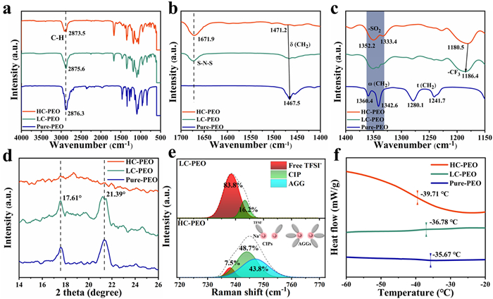
These structural transformations of the polymer are also corroborated by X-ray diffraction (XRD) analysis (Fig. 1d), showing complete suppression of the characteristic PEO crystalline peak at 21.39° in HC-PEO membranes accompanied by substantial attenuation of the 17.61° peak intensity. Raman spectroscopy (Fig. 1e) quantifies ionic association states through TFSI− vibrational modes: free anions (737 cm-1), contact ion pairs (CIPs, 744 cm-1), and aggregated clusters (AGGs, 749 cm-1). Quantitative analysis demonstrates a dramatic salt concentration effect: free TFSI− population suddenly drops from 81.8% in LC-PEO to 7.5% in HC-PEO, while CIPs and AGGs collectively rise to 91% (48% CIPs and 43% AGGs), establishing percolated ion-conduction network. Differential scanning calorimetry (DSC) reveals the segmental motion of the polymers (Fig. 1f), where HC-PEO exhibits a depression in glass transition temperature from −35.67 ℃ to −39.71 ℃, reflecting enhanced chain mobility through the disruption of crystalline phase. The results demonstrate that increasing NaTFSI concentration disrupts the semicrystalline order of SPEs while accelerating segmental mobility via salt-induced plasticizing effects. This structural optimization achieves molecular-level architectural control over ionic transport and polymer chain dynamics.
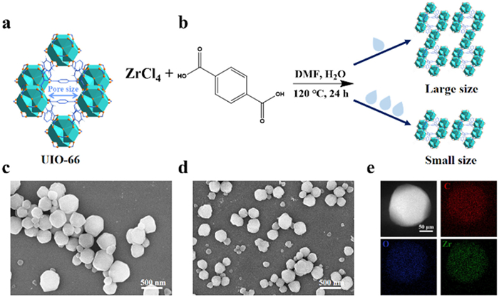
In MOF structures designed for TFSI−-trapping functionality, precise pore size engineering is critical to align with the target anion's dimensions while ensuring TFSI− sieving capabilities. UIO-66, a zirconium-based metal-organic framework with 1, 4-dicarboxybenzene ligands, exhibits a stable octahedral topology and hierarchical porosity. The archetypal UIO-66 framework exhibits a characteristic pore size of 0.75–0.81 nm [52], as validated by above structural modeling (Fig. 2a), enabling efficient migration of Na+ or solvated Na+ ions (1.02 Å). This pore dimension is strategically relevant to TFSI− anion interactions, where the framework's tailored porosity facilitates size-selective confinement. The rigid pore architecture of UIO-66 ensures chemical and thermal stability, while the 1, 4-dicarboxybenzene ligand further enhances anion affinity through electrostatic or coordination-based mechanisms. Such synergistic alignment of pore geometry and chemical compatibility underpins UIO-66′s efficiency in TFSI− sieving capabilities (0.79 nm) [53]. Unlike the random dispersion of MOF particles in polymer matrices, the rational design precisely encapsulates size-controlled UIO-66 nanoparticles within electrospun PAN nanofibers (Fig. 2b) delineates the solvothermal synthetic pathway of UIO-66, where modulation of particle size was achieved through controlled water addition in the DMF solvent system. SEM micrographs (Figs. 2c and d) directly compared a progressive crystallite refinement of UIO-66 through the solvent-mediated strategy. Subsequent optimization of the water dosage (0.9 wt% in DMF, Fig. S1 in Supporting information) enabled further refinement of the UIO-66 crystal grains from 600 nm-1 mm (Fig. 2c) to 200–400 nm (Fig. 2d) [54]. As compared to the incomplete large UIO-66 particle encapsulation in PAN fibers, the optimized particles of 200–250 nm were preferentially employed for electrospinning integration with PAN fibrous matrix. Structural validation through EDS elemental mapping (Fig. 2e) demonstrates homogeneous spatial distribution of characteristic C, Zr, and O signals. XRD analysis (Fig. S2 in Supporting information) reveals standard R-3c space group pattern of UIO-66. N2 adsorption-desorption isotherms of UIO-66 samples are exhibited in Fig. S3 (Supporting information), revealing a Brunauer-Emmett-Teller (BET) surface area of 730.1 m2/g and a well-defined pore size range of 7.5–8.1 Å. This structural alignment confirms the successful synthesis of phase-pure UIO-66 with the desired nanoporous framework.
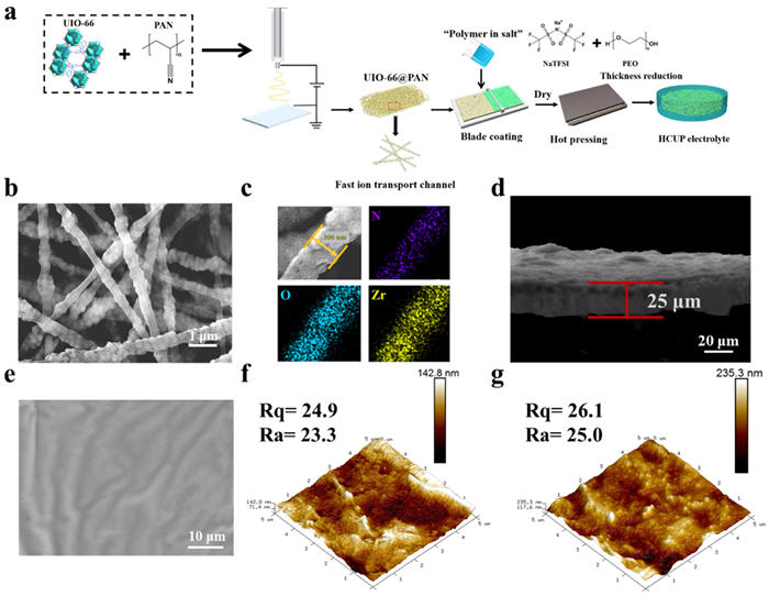
Furthermore, we engineered dimensionally optimized CPEs by developing a UIO-66@PAN electrospun framework through systematic process optimization. As schematically illustrated in (Fig. 3a), the fabrication process involved blade-casting HC-PEO slurry onto UIO-66@PAN scaffolds followed by thermal pressing (65 ℃) to create the thin-layer HCUP membranes. A control sample (HC-PEO@PAN, abbreviated as HCP electrolyte) was also prepared without UIO-66 encapsulation in the electrospun PAN fibers. Critical electrospinning parameters were regulated through voltage-dependent morphology. As evidenced in (Figs. S4a and b in Supporting information), excessive voltages (> 20 kV) induced PAN nanofiber diameter reduction below 200 nm, resulting in defective nanoparticle encapsulation. Through iterative testing, optimal processing at 15 kV produced 400 nm-diameter PAN nanofibers that effectively embedding 200–400 nm UIO-66 particles. SEM imaging and corresponding EDS mapping confirmed homogeneous Zr distribution along the fibers, verifying the complete, continuous UIO-66 integration within the nanofiber matrix (Figs. 3b and c). The UIO-66 nanoparticles exhibited uniform spatial distribution along nanofiber axis while the nanofibers still maintain the three-dimensional interconnectivity. This percolating architecture thus establishes continuous ion transport pathways, significantly enhancing Na+ mobility. Comparative analysis with pure-PAN scaffolds (Fig. S5 in Supporting information) further highlights the critical role of UIO-66 incorporation in constructing this hierarchical ion-transport network. UIO-66@PAN scaffolds showed 58% higher tensile strength than the control of pure-PAN scaffold (Fig. S6 in Supporting information). The phenomenon could be attributed to the nanoparticle-induced physical crosslinking effect that reinforces nanofiber interconnectivity. Thermal gravimetric analysis (TGA) demonstrated decomposition onset temperatures of 180 ℃ for the UIO-66@PAN and 150 ℃ for the pure-PAN scaffold, both exceeding the polyolefin PE/PP separators (Fig. S7 in Supporting information). This thermal-mechanical synergy promises the structural integrity of the CPE under realistic high-temperature operation conditions. SEM analysis in (Figs. 3d and e) demonstrates the HCUP membrane's compact 25 µm-thick architecture with homogeneous phase distribution, which significantly reduces Na+ diffusion pathways. Surface topography characterization through atomic force microscope (AFM) reveals comparable roughness parameters between HCUP and HCP membranes (Figs. 3f and g), critical for maintaining uniform electrode-electrolyte interfacial contact and subsequent dendrite mitigation. This integrated engineering approach systematically combines three key elements: dimension optimization (achieving sub-30 µm thickness), mechanical reinforcement design, and ion-transport pathway engineering, thereby resolving the inherent thickness-ionic conductance trade-off in solid-state electrolyte systems.
Mechanical and electrochemical characterization of the LC-PEO, HC-PEO, HCP, and HCUP electrolyte membranes revealed substantial performance improvements through UIO-66 integration. Tensile testing (Fig. 4a) demonstrated the HCUP membrane exceptional mechanical strength (3.46 MPa), surpassing the HCP (2.85 MPa), HC-PEO (0.47 MPa), and LC-PEO (0.96 MPa), confirming the UIO-66@PAN framework effectiveness in mechanical reinforcement and dendrite inhibition. Linear sweep voltammetry (LSV, Fig. 4b) showed expanded electrochemical stability windows for HCUP (4.72 V) compared to HCP (4.53 V), HC-PEO (4.37 V), and LC-PEO (4.02 V), attributed to synergistic effects from high salt concentration suppressing PEO decomposition; the PAN nanofibers contain a large number of C≡N functional groups with a strong electron-withdrawing effect, thereby enhancing the antioxidant performance of the electrolyte membrane; in addition, the UIO-66 particles themselves have excellent high-voltage tolerance, and these factors together promote the step-by-step increase in the electrochemical window to 4.72 V.
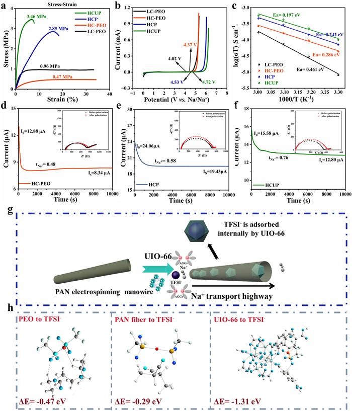
The addition of UIO-66 nanoparticles can significantly enhance the ionic conduction performance of PEO-based high-concentration salt electrolytes. As shown in (Fig. 4c) and Table S1 (Supporting information), the HCUP electrolyte exhibited higher ionic conductivity (1.01 × 10⁻⁴ S/cm) than the HCP electrolyte (7.16 × 10⁻⁵ S/cm), HC-PEO electrolyte (4.36 × 10⁻⁵ S/cm) and LC-PEO electrolyte (8.15 × 10⁻⁶ S/cm) at 30 ℃. In addition, according to the Arrhenius equation, the activation energy (Ea) of various electrolyte membranes was derived. The Ea of HCUP electrolyte was 0.197 eV, which was much lower than HCP (0.242 eV), HC-PEO (0.286 eV) and LC-PEO (0.461 eV), indicating that Na+ migration in HCUP CPE requires a low energy barrier. The significant increase in the ionic conductivity of HCUP electrolyte can be attributed to the synergistic construction of Na+ transport pathways by TFSI- anion clusters formed at high salt concentrations and highly interconnected UIO-66 particles, achieving rapid transfer of Na+. As shown in (Figs. 4d-f and Fig. S8 in Supporting information), the HCUP electrolyte achieves a notably higher Na+ transference number (tNa+) of 0.76, as opposed to 0.58 for HCP electrolyte, 0.48 for HC-PEO electrolyte and 0.17 for LC-PEO electrolyte. The significant enhancement in the transference number of the HCUP electrolyte can be primarily attributed to the synergistic effects of multiple factors. The high-concentration salt leads to the formation of TFSI− anion clusters, which significantly restrict the transport of TFSI- anions. Moreover, the pore size of UIO-66 (8.1 Å) is slightly larger than that of the TFSI− anion (7.9 Å), enabling the effective capture and immobilization of TFSI− anions through size exclusion. Additionally, the surface charge of UIO-66, characterized by strong cationic sites, exerts electrostatic interactions that further limit the migration of TFSI− anions. Furthermore, the highly interconnected UIO-66 nanoparticles between PAN nanofibers form continuous ion transport pathways, which facilitate and accelerate the transfer of Na+ ions (Fig. 4g). The adsorption properties of UIO-66 nanoparticles toward TFSI− anions were further substantiated by density functional theory (DFT) calculations. As depicted in (Fig. 4h), the adsorption energy between UIO-66 and TFSI− (−1.31 eV) was significantly higher than that between TFSI− and PEO (−0.47 eV) or PAN fibers (−0.29 eV), respectively. This indicates a stronger interaction between UIO-66 and TFSI−, which weakens the electrostatic bonding between TFSI− and Na+. The UIO-66 framework effectively traps TFSI− anions through steric-electronic confinement, suppressing their migration. Simultaneously, it enables selective Na+ transport via cation-specific channels within the UIO-66@PAN matrix, promoting unidirectional Na+ diffusion.
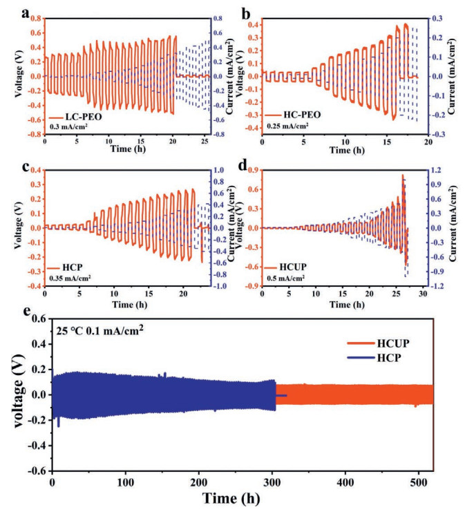
To systematically evaluate the interfacial stability and electrochemical polarization characteristics of the HCUP electrolyte, critical current density (CCD) measurements were conducted under progressive current ramping conditions. As demonstrated in (Figs. 5a-d), conventional LC-PEO and HC-PEO electrolytes exhibited premature short-circuiting at 0.3 and 0.25 mA/cm2 respectively, indicative of non-uniform sodium deposition and dendritic penetration at low current densities. The PAN-reinforced HCP electrolyte showed improved CCD performance (0.35 mA/cm2), attributable to enhanced mechanical resilience from the nanofiber scaffold. Remarkably, the HCUP electrolyte demonstrated superior dendrite resistance with a CCD value of 0.5 mA/cm2. Extended cycling evaluation of Na||Na symmetric cells at 0.1 mA/cm2 (Fig. 5e) revealed fundamental performance differences: HCP cells failed after 300 h with excessive polarization (> 120 mV), while HCUP cells maintained stable operation for 1100 h with minimal polarization (~30 mV). This performance enhancement arises from UIO-66 synergistic functionalities. The precisely sized pores selectively immobilize TFSI− anions through molecular sieving effects while the interconnected 3D UIO-66@PAN framework mechanically suppresses dendrite propagation, collectively promoting the uniform deposition of Na.
The HCUP CPE was systematically evaluated in the full-cell model, pairing with a high-capacity-loading NVP cathode (1 mAh/cm2) and Na foil. Benefiting from the facile interfacial kinetics toward the Na foil, the NVP||HCUP||Na model exhibited impressive high-current-density endurance (Figs. 6a and b), which delivering discharge capacities of 103.8 mAh/g at 0.1 C, 100.4 mAh/g at 0.2 C, 95.9 mAh/g at 0.5 C and 90.5 mAh/g at 1 C, respectively, markedly superior to the NVP||HCP||Na counterpart. Notably, the discharge capacity of the NVP||HCUP||Na could recover to 103.4 mAh/g as the cycling rate returned to 0.1 C, as compared to only 95.9 mAh/g for the NVP||HCP||Na cell. At room temperature, the full cell model with HCP exhibited rapid capacity degradation, retaining only 81.2% of initial capacity after 200 cycles. The NVP||HCUP||Na model further extended the cycle life of the full cell model, which well maintained a retrievable capacity of 105.1 mAh/g with 91.3% capacity retention for 200 cycles (Fig. 6c). As cycling rate increased to 0.3 C, the cell with HCUP still retained 90.9% capacity retention of its initial capacity after 100 cycles (Fig. 6d), far outperforming the models with HCP CPE (85.4% after 100 cycles). As shown in (Fig. 6e), the NVP||HCUP||Na model exhibited high-temperature tolerance, which maintained 95.8% capacity retention for 100 cycles at 80 ℃.
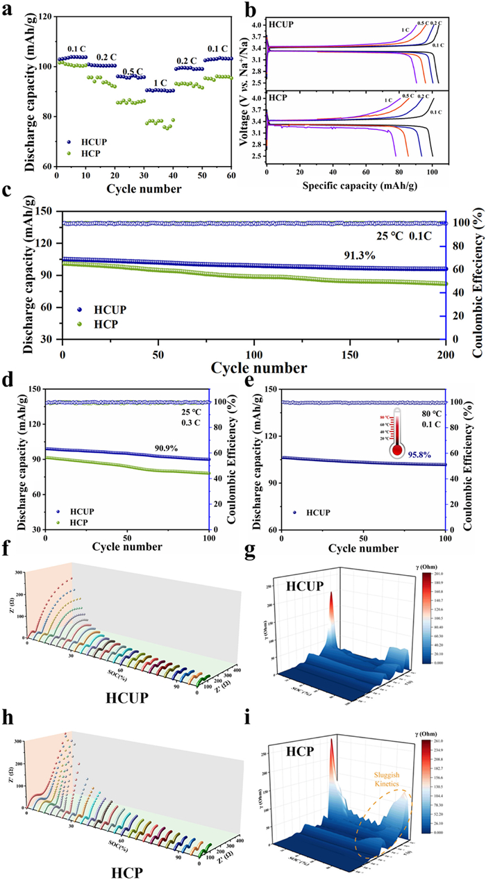
The combined application of in situ galvanostatic electrochemical impedance spectroscopy (GEIS) and distribution of relaxation times (DRT) analysis revealed critical insights into how Na salt aggregates and size-selective anion modulate Na+ diffusion kinetics at the cellular scale. Figs. 6f-i comparatively display the interfacial impedance evolution during the initial discharging process in NVP||HCUP||Na and NVP||HCP||Na pouch-type cells. With identical NVP cathodes and HCUP electrolytes implemented, the impedance difference predominantly originates from the electrode-electrolyte interface, which serves as the primary rate-limiting factor for overall reaction kinetics. As shown in Figs. 6f-h, during the discharging process, the impedance of the NVP||HCP||Na cell increases significantly from 54 Ω to 122 Ω, whereas the resistance of the NVP||HCUP||Na cell remains nearly constant under identical conditions. This phenomenon can be ascribed to the formation of a robust solid electrolyte interphase (SEI) layer by the HCUP during cycling, which facilitates uniform Na deposition.
The DRT analysis (Figs. 6g-i) reveals distinct kinetic domains through time-constant (τ) distribution: The peak at τ = 10–5–10–3 s represents irreversible phase transformations, attributable to ionic transport during solid electrolyte interphase (SEI) formation. Processes with τ = 10–3–10–2 s are associated with charge transfer resistance (Rct), while components in the τ = 10–1–100 s range correspond to Na+ diffusion resistance (Rd) at the anode interface. Notably, the HCUP electrolyte demonstrates significantly lower interfacial Rct and Rd values compared to conventional HCP, as evidenced by reduced peak intensities in both time-constant regions. This dual reduction in interfacial resistances facilitates more efficient Na+ transport and enhanced charge transfer kinetics during electrochemical cycling. The anion-regulation strategy of HCUP electrolyte enhances the electrolyte-anode interfacial compatibility, thereby establishing essential interfacial stability for high-rate operation in ASSMBs.
Additionally, as shown in Fig. S9 (Supporting information), a safety evaluation of the ASSMB pouch cell was conducted under extreme conditions. The single-layer NVP||HCUP||Na pouch cell successfully powered a miniature bulb while maintaining operational stability during mechanical stress tests, including bending and partial cutting scenarios.
In summary, we proposed a hierarchically engineered CPE design via the anion-regulation strategy, which integrated the high-concentration ion clusters with a mechanically reinforced, molecular-sieving UIO-66@PAN scaffold. The ultrathin (25 µm), lightweight (1.76 mg/cm2) HCUP membrane achieved an order-of-magnitude enhancement in mechanical strength (3.46 MPa) and ionic conductivity (1.01 mS/cm at 30 ℃) compared to pristine LC-PEO electrolytes, enabled by high-concentration TFSI− dissociation that activates mobile anion-Na+ clusters, thus the as-formed dynamic percolation networks mitigated the energy barrier of Na+ diffusion. Simultaneously, the UIO-66@PAN scaffold utilized sub-nanometer pore precision (7.5–8.1 Å vs. TFSI− for 7.9 Å) to impose steric-electronic anchoring effects, immobilizing TFSI− anions and yielding a high Na+ transference number (tNa+ = 0.76). When assembled into a solvent-free, layer-stacked ASSMB configuration with NVP cathode (1 mAh/cm2) and Na foil, the prototype demonstrated 91.3% capacity retention over 200 cycles at room temperature and operation reliability from 25 ℃ to 80 ℃. This synergistic combination of ion cluster engineering and molecular-sieving architectures establishes a strategic, feasible paradigm for practical ASSMBs construction with wide-temperature adaptability and sustainable recyclability.
Yuxiang Guo: Writing – original draft, Validation, Methodology, Investigation, Formal analysis, Data curation. Peiwen Fan: Visualization, Software, Methodology, Investigation, Formal analysis, Data curation. Jiacheng Liu: Software, Resources, Investigation, Formal analysis. Qinpeng Qiao: Visualization, Validation, Software, Methodology. Ahu Shao: Resources, Investigation, Formal analysis. Lu Cheng: Visualization, Validation, Software. Jiawen Tang: Software, Investigation, Formal analysis. Yaxin Zhang: Validation, Software, Investigation. Zhiqiao Wang: Software, Methodology, Formal analysis. Yunsong Li: Software, Methodology, Investigation. Helin Wang: Software, Formal analysis. Chunwei Li: Visualization, Software. Junyu Zhang: Software, Investigation. Yue Ma: Writing – review & editing, Funding acquisition, Conceptualization.
The authors declare that they have no known competing financial interests or personal relationships that could have appeared to influence the work reported in this paper.
The authors acknowledge the financial support of the National Natural Science Foundation of China (Nos. 52173229 and 52373229) and the Natural Science Foundation of Shaanxi (No. 2023-JC-JQ-15). Furthermore, the authors also would like to thank the Analytical & Testing Center of Northwestern Polytechnical University for providing several testing instruments.
Supplementary material associated with this article can be found, in the online version, at doi:
Y. Lu, L. Li, Q. Zhang, Z. Niu, J. Chen, Joule 2 (2018) 1747–1770. doi: 10.1016/j.joule.2018.07.028
Y. Su, F. Xu, X. Zhang, Y. Qiu, H. Wang, Nano-Micro Lett. 15 (2023) 023–01055-z.
Z. Bi, S. Mu, N. Zhao, et al., Energy Storage Mater. 35 (2021) 512–519. doi: 10.1016/j.ensm.2020.11.038
Z. Ye, S. Zhai, R. Liu, et al., Chem. Eng. J. 479 (2024) 147847. doi: 10.1016/j.cej.2023.147847
Z. Guo, G. Qian, C. Wang, et al., Prog. Nat. Sci. : Mater. Int. 33 (2023) 1–7.
Q. Yu, K. Jiang, C. Yu, et al., Chin. Chem. Lett. 32 (2021) 2659–2678. doi: 10.1016/j.cclet.2021.03.032
X. Shan, M. Morey, Z. Li, et al., ACS Energy Lett. 7 (2022) 4342–4351. doi: 10.1021/acsenergylett.2c02349
H. Liang, L. Wang, A. Wang, et al., Nano-Micro Lett. 15 (2023) 022–00996-00991.
W. Tang, R. Qi, J. Wu, et al., Electrochem. Energy Rev. 7 (2024) 024-00228-00227.
C. Zhao, L. Liu, X. Qi, et al., Adv. Energy Mater. 8 (2018) 1703012. doi: 10.1002/aenm.201703012
X. Huang, R. He, M. Li, et al., Mater. Today 41 (2020) 143–155. doi: 10.1016/j.mattod.2020.07.015
M. Zhang, H. Wang, A. Shao, et al., Adv. Energy Mater. 14 (2024) 2303932. doi: 10.1002/aenm.202303932
D. Kim, X. Hu, B. Yu, Y.I. Chen, Adv. Mater. 36 (2024) 2401625. doi: 10.1002/adma.202401625
H. Xu, S. Yang, B. Li, Adv. Energy Mater. 14 (2024) 2303539. doi: 10.1002/aenm.202303539
N. Ding, S.W. Chien, T.L.D. Tam, et al., Adv. Energy Mater. 14 (2024) 2402986. doi: 10.1002/aenm.202402986
C. Yang, Q. Wu, W. Xie, et al., Nature 598 (2021) 590–596. doi: 10.1038/s41586-021-03885-6
F. He, W. Tang, X. Zhang, L. Deng, J. Luo, Adv. Mater. 33 (2021) 2105329. doi: 10.1002/adma.202105329
R. Li, H. Hua, Y. Zeng, et al., J. Energy Chem. 64 (2022) 395–403. doi: 10.1016/j.jechem.2021.04.037
Y. Yu, W. Gao, Y. Peng, et al., Chin. Chem. Lett. 37 (2026) 111309. doi: 10.1016/j.cclet.2025.111309111309
Y. Wei, T.H. Liu, W. Zhou, et al., Adv. Energy Mater. 13 (2023) 2203547. doi: 10.1002/aenm.202203547
H. Cheng, Z. Ma, P. Kumar, ACS Energy Lett. 9 (2024) 1604–1616. doi: 10.1021/acsenergylett.3c02789
X. Wang, C. Zhang, M. Sawczyk, et al., Nat. Mater. 21 (2022) 1057–1065. doi: 10.1038/s41563-022-01296-0
S. Tang, Q. Lan, L. Xu, et al., Nano Energy 71 (2020) 104600. doi: 10.1016/j.nanoen.2020.104600
M.S.M. Misenan, A.S.A. Khiar, T. Eren, Polym. Int. 71 (2022) 751–769. doi: 10.1002/pi.6395
H. Kokubo, E. Nakazawa, M. Watanabe, Polym. Adv. Technol. 30 (2018) 736–742.
X. Zeng, X. Liu, H. Zhu, et al., Adv. Energy Mater. 14 (2024) 2402671. doi: 10.1002/aenm.202402671
Y.W. Song, S.J. Park, H. Lee, et al., J. Mater. Chem. A 12 (2024) 9594–9605. doi: 10.1039/d4ta00479e
X. Lin, C. Chu, Z. Li, et al., Nano Energy 89 (2021) 106351. doi: 10.1016/j.nanoen.2021.106351
J. Ou, G. Li, Z. Chen, J. Electrochem. Soc. 166 (2019) A1785–A1792. doi: 10.1149/2.0401910jes
E. Kim, H. Jamal, I. Jeon, et al., Adv. Energy Mater. 13 (2023) 2301674. doi: 10.1002/aenm.202301674
S. Yang, X. He, T. Hu, et al., Adv. Funct. Mater. 33 (2023) 2304727. doi: 10.1002/adfm.202304727
J. Park, H. Seong, C. Yuk, et al., Adv. Mater. 36 (2024) 2403191. doi: 10.1002/adma.202403191
Z. Zhang, Q. Zhang, J. Shi, et al., Adv. Energy Mater. 7 (2016) 1601196.
S. He, Y. Xu, Y. Chen, X. Ma, J. Mater. Chem. A 8 (2020) 12594–12602. doi: 10.1039/c9ta12213c
J. Naik, R.F. Bhajantri, V. Hebbar, S.G. Rathod, Adv. Compos. Hybrid Mater. 1 (2018) 518–529. doi: 10.1007/s42114-018-0030-9
P.N. Didwal, Y.N. Singhbabu, R. Verma, et al., Energy Storage Mater. 37 (2021) 476–490. doi: 10.1016/j.ensm.2021.02.034
X. Li, Y. Pan, Y. Liu, et al., Carbon Neutrality 2 (2023) 34. doi: 10.1007/s43979-023-00074-4
Y. Yusim, E. Trevisanello, R. Ruess, et al., Angew. Chem. Int. Ed. 62 (2023) e202218316. doi: 10.1002/anie.202218316
W. Liu, C. Yi, L. Li, et al., Angew. Chem. Int. Ed. 60 (2021) 12931–12940. doi: 10.1002/anie.202101537
M. Sun, Z. Zeng, W. Zhong, et al., J. Mater. Chem. A 10 (2022) 11732–11741. doi: 10.1039/d2ta00093h
J. Zhang, Y. Wang, Q. Xia, et al., Angew. Chem. Int. Ed. 63 (2024) 2318822.
P. Zhai, S. Qu, N. Ahmad, et al., Small 20 (2024) 2310547. doi: 10.1002/smll.202310547
Y.L. Ni'mah, M.Y. Cheng, J.H. Cheng, J. Rick, B.J. Hwang, J. Power Sources 278 (2015) 375–381. doi: 10.1016/j.jpowsour.2014.11.047
A.G. Nguyen, R. Verma, G.C. Song, J. Kim, C.J. Park, Adv. Sci. 10 (2023) 2207744. doi: 10.1002/advs.202207744
J. Lu, J. Zhou, R. Chen, et al., Energy Storage Mater. 32 (2020) 191–198. doi: 10.1016/j.ensm.2020.07.026
D. Zhou, X. Tang, X. Guo, et al., Angew. Chem. Int. Ed. 59 (2020) 16725–16734. doi: 10.1002/anie.202007008
J. Wan, J. Xie, X. Kong, et al., Nat. Nanotechnol. 14 (2019) 705–711. doi: 10.1038/s41565-019-0465-3
M.M. Hassan, X.Y. Wang, A.A. Bristi, et al., Nano Energy 128 (2024) 109971. doi: 10.1016/j.nanoen.2024.109971
J.H. Yim, B.K. Oh, J.S. Lim, J. Chem. Engin. Data 65 (2020) 4S378–44386. doi: 10.1021/acs.jced.0c00188
C. Luo, Q. Li, D. Shen, et al., Energy Storage Mater. 43 (2021) 463–470. doi: 10.1016/j.ensm.2021.09.031
H. Ye, C. Zhang, Y. Li, et al., Prog. Nat. Sci. Mater. Int. 33 (2023) 754–766. doi: 10.1016/j.pnsc.2023.12.018
J.H. Cavka, S. Jakobsen, U. Olsbye, et al., J. Am. Chem. Soc. 130 (2008) 13850–13851. doi: 10.1021/ja8057953
Z. Li, S. Wang, J. Shi, et al., Energy Storage Mater. 47 (2022) 262–270. doi: 10.1016/j.ensm.2022.02.014
G.E. Decker, Z. Stillman, L. Attia, C.A. Fromen, E.D. Bloch, Chem. Mater. 31 (2019) 4831–4839. doi: 10.1021/acs.chemmater.9b01383

Scheme 1 Schematic illustration of the Na+ conducting mechanism in the LC-PEO, HC-PEO as well as the HC-PEO/UIO-66@PAN (HCUP) electrolyte.

Figure 1 FTIR spectra for pure-PEO, LC-PEO and HC-PEO at (a) 4000–1500 cm-1, (b) 1700–1400 cm-1, and (c) 1400–1150 cm-1. (d) XRD patterns of pure-PEO, LC-PEO, and HC-PEO electrolytes. (e) Raman spectra for LC-PEO and HC-PEO electrolytes at 720–770 cm-1. (f) DSC curves of pure-PEO, LC-PEO, and HC-PEO electrolytes.

Figure 2 (a) The crystalline structure of UIO-66 with specific pore size range. (b) Schematic diagram of the synthesis route of UIO-66 particle with tunable size. SEM images of UIO-66 of (c) large-size particles and (d) small-size particles. (e) High-angle annular dark field (HAADF) image and the corresponding elemental mappings of representative UIO-66 particle with C, O and Zr signals.

Figure 3 (a) Schematic illustration of HC-PEO/UIO-66@PAN membrane. (b) SEM images of 3D UIO-66@PAN framework. (c) EDS mapping of 3D UIO-66@PAN framework with characteristic N, O, and Zr signals. (d) Cross-sectional SEM image of HCUP membrane. (e) The top-view SEM image of HCUP membrane. The AFM images of (f) HCP electrolyte membrane and (g) HCUP electrolyte membrane.

Figure 4 (a) Stress-strain curves of LC-PEO, HC-PEO, HCP, and HCUP electrolytes. (b) LSV curves of LC-PEO, HC-PEO, HCP, and HCUP electrolytes. (c) Ionic conductivities of LC-PEO, HC-PEO, HCP and HCUP electrolytes. The chronoamperometry curves of (d) HC-PEO, (e) HCP, and (f) HCUP CPEs. (g) Schematic illustration of the UIO-66 encapsulation in PAN fibers for enhanced cationic transference. (h) Adsorption energies between TFSI- with PEO, PAN fibers and UIO-66.

Figure 5 Galvanostatic Na plating/stripping profiles of (a) Na||LC-PEO||Na, (b) Na||HC-PEO||Na, (c) Na||HCP||Na and (d) Na||HCUP||Na at stepwise increased current densities at 60 ℃. (e) Comparison of the plating/stripping process of Na||HCP||Na and Na||HCUP||Na cells with a current density of 0.1 mA/cm2.

Figure 6 (a) The rate performance of NVP||HCUP||Na and NVP||HCP||Na models within 2.5–4.0 V. (b) Charge/discharge curves of the NVP||HCUP||Na and NVP||HCP||Na models. (c) The room-temperature cycling performance of NVP||HCUP||Na and NVP||HCP||Na models at 0.1 C. (d) The room-temperature cycling performance of NVP||Na models with HCUP, and HCP CPEs at 0.3 C. (e) Cycling performance of NVP||HCUP||Na model at 80 ℃. Interfacial impedance evolution of the (f) NVP||HCUP||Na and (h) NVP||HCP||Na during the initial charging process; and (g, i) corresponding DRT transformation of in situ GEIS.

 扫一扫看文章


扫一扫关注我们
 DownLoad:
 下载:
下载:
 下载:
下载: