Received Date:
09 April 2025 Accepted Date:
17 June 2025 Revised Date:
14 June 2025 Available Online:
15 September 2026
Abstract:
Composite bipolar plates (CBPs) composed of resin and conductive fillers have the potential to combine excellent conductivity with superior mechanical properties, as key components in proton exchange membrane fuel cells (PEMFCs). However, the industrial scalability is hindered by slow curing kinetics and trade-offs between conductivity and mechanical integrity. In this work, we propose a rapid compression molding strategy catalyzed by 2-methylimidazole (2MI), which utilizes the synergistic effect of tertiary amine catalysis and nucleophilic enhancement to reduce the energy barrier of epoxy ring opening, enabling the resin to achieve ultrafast curing. And with temperature and pressure regulation, CBPs achieve good contact between graphite particles and a dense structure, resulting in outstanding in-plane conductivity of 190 S/cm, flexural strength of 85 MPa, and hydrogen permeability below 1.5 × 10⁻¹⁰ cm3/(cm2 s). The work provides a paradigm for resin-curing synergy, bridging rapid processing with multifunctional performance, and advancing scalable PEMFC component manufacturing.
Proton exchange membrane fuel cells (PEMFCs) are widely regarded as important candidates for future energy substitution technologies due to their zero emissions, high energy efficiency, and low noise characteristics, demonstrating unique advantages and potential in various fields such as transportation, decentralized power stations, and aerospace [1–3]. As the main component of PEMFC, bipolar plates play an important role in supporting the membrane electrode assembly (MEA), conducting current, and separating gases, requiring sufficient mechanical strength, excellent conductivity, and gas impermeability [4–6]. Additionally, within the humid and acidic environment inside the cell, they need to exhibit good thermal conductivity and resistance to electrochemical corrosion [7]. Therefore, the application of brittle graphite plates and metal plates that are susceptible to surface corrosion and passivation is limited [7–11].
CBPs are manufactured through the blending and compression of carbon-based conductive fillers and polymer resins [12]. The conductive network created by filler interactions forms the foundational structure for achieving superior electrical conductivity [13]. The adhesion between fillers and polymers enhances overall mechanical strength, while both materials exhibit satisfactory resistance to corrosion [14]. Consequently, CBPs represent a promising type of bipolar plate that combines high electrical conductivity, robust mechanical properties, low gas permeability, and high corrosion resistance. Yao et al. prepared CBPs by hot pressing graphite oxide/epoxy resin composite materials using a flat vulcanizing machine for 90 min, with a flexural strength of up to 67.3 MPa [14]. Yan et al. utilized the hot-pressing method to fabricate graphite/epoxy resin CBPs doped with nano-copper, with the average conductivity of up to 168.12 S/cm for 89G+1Cu composite [15]. Chen et al. developed a resin network structure rich in flexible chain segments by copolymerizing phenolic resin with epoxy resin [16]. This resin matrix was mixed with graphite and hot-pressed for 2 h to fabricate CBPs, which exhibited higher flexural strength (86.97 MPa) and electrical conductivity (203.22 S/cm). Despite this, the slow curing reaction results in extended thermal molding times, significantly limiting the molding efficiency, which is not conducive to large-scale production [17].
So, how to improve this efficiency? One method is to adjust the resin formulation system to accelerate the reaction rate, thereby shortening the curing reaction time, and improve the molding efficiency of CBPs [17–19]. Liu et al. designed a novel structural flame retardant and promoter DOPO—CDI, in which the imidazole groups nucleophilically attack the epoxy bonds of DGEBA to generate alkoxide negative ions, and further react with the epoxy bonds and DDM, significantly shortening the gelation time and improving processing efficiency [20]. Yousefi et al. developed carbon fiber preforms using lower-cost solid epoxy resin formulations [18]. 1 wt% accelerator was incorporated to reduce the curing time of the resins from 8 h to 16 min. Wang et al. developed a series of phosphorus-containing imidazolium compounds as multifunctional latent hardeners for one-component epoxy resins [19]. EP/BADM-X demonstrated rapid gelation at 100 ℃, along with excellent low-temperature processability and tunable curing activity. In view of this, we used 2-methylimidazole (2MI) as a promoter for curing epoxy resin with 4,4′-diaminodiphenyl sulfone (4,4′-DDS) in this work. Its structure contains two nitrogen atoms, one of which forms a secondary amine and the other forms a tertiary amine, endowing it with both secondary amine and tertiary amine catalytic functions, exhibiting high catalytic and crosslinking efficiency [21].
In addition, the temperature and pressure during the molding process significantly influence the curing and rheological behavior of the material, which in turn determine the structure and properties of plates [22,23]. Xiao et al. investigated the effect of the flowability of the bulk-molding compound on the formability of CBPs [24]. Research demonstrated that a decrease in the flowability of the molding compound leads to the formation of defects in CBPs, potentially causing obvious cracks or even failed forming of CBPs. Witpathomwong et al. utilized polybenzoxazine as a substrate for CBPs due to its extremely low viscosity and excellent flowability at the forming temperature, which facilitates the composite processing [25]. However, the mechanism by which temperature and pressure influence the structure and properties of plates has not been further explored. Therefore, the resin system described above was mixed with graphite for efficient molding, and the effect of temperature and pressure on structure was investigated, ultimately resulting in CBPs with favorable conductivity, mechanical properties, and gas impermeability. This provides a theoretical foundation for the formulation screening and performance optimization of CBPs.
Epoxy resin, 4,4′-DDS and 2MI were purchased from Shanghai Macklin Biochemical Technology Co., Ltd. The value of epoxy groups in EP is 0.46–0.5 mol/100 g, and the viscosity is 1100–1600 MPa s at room temperature. Natural flake graphite (NFG, 99.95%) with a particle size of 320 mesh was supplied by Shenzhen Hanhui Graphite. Ethanol (AR, ≥ 99.7%) was procured from Sinpharm Chemical Reagent Co., Ltd.
Mix epoxy resin, 4,4′-DDS, and 2MI in a glass beaker at a mass ratio of 100:30:1, and then stir thoroughly at room temperature for about 30 min to obtain a homogeneous resin. Subsequently, combine graphite with the resin at a mass ratio of 8:2, then introduce ethanol into the mixture. Mechanically stir at 500 rpm at room temperature until a homogeneous mixture is achieved. Allow the mixture to air dry in an oven at 60 ℃ for 2 h to yield the graphite/epoxy composite material. Finally, mold the composite material rapidly at various temperatures and pressures for 5 min. The molding pressure strategy is showed in Fig. S1 (Supporting information).
Thermogravimetric analysis (TGA, Netzsch STA 449F3, Netzsch) was performed under nitrogen at a heating rate of 10 ℃/min to investigate thermal stability. Differential scanning calorimetry (DSC, TA DSC250, TA) was employed to study the curing kinetics in non-isothermal scans at heating rates of 2.5, 5, 10, 15 and 20 ℃/min over the temperature range of 30–250 ℃ under nitrogen. The structure of epoxy resin, 4,4′-DDS, and 2MI was detected by Fourier-transform infrared spectrometer (FTIR, Nicolet iS20, Thermo Fisher Scientific), and the curing reaction was monitored by in-situ FTIR (Nicolet iS50, Thermo Fisher Scientific) across the wavenumber range of 4000–400 cm-1 with a resolution of 4.0 cm-1. Rheological measurements were carried out in a modular compact rheometer (MCR 302e, Anton Paar) equipped with a parallel plate geometry (25 mm plate diameter) in dynamic oscillation mode at 10 Hz and a strain amplitude of 1%.
The microstructure and morphology of CBPs were characterized using optical microscope (OM, VHX-S90BE, Keyence) and scanning electron microscope (SEM, GeminiSEM 300, Carl Zeiss). The cross sections of CBPs were polished using a cross section polisher (CCP, IB-19520CCP, JEOL) before morphology observation. The pore structure was analyzed by computed tomography (CT, nanoVoxel-4000, Sanying Precision Instruments). In-plane conductivity and area specific resistance (ASR) of CBPs were investigated by a resistance tester (FT-541SJB-341, Rooko). The flexural strength was measured by three-point bending method on Universal Testing Machine (UTM, Instron Model 3365, Instron). The H2 permeability of CBPs were tested by helium mass spectrometer leak detector (A100, Armstech).
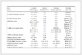
TGA was performed to determine the thermal stability of the resin, as shown in Fig. S2 (Supporting information). The resin begins thermal decomposition at approximately 250 ℃, with the maximum degradation being observed at 405.11 ℃. The conversion rate and released heat during the non-isothermal curing process of the resin were measured using dynamic DSC with a constant heating rate. The heat flow curves obtained at different heating rates were depicted in Fig. 1a. The spectrum manifests only a single peak, indicating that the reaction follows an autocatalytic polymerization mechanism, with mutual interaction between 2MI and 4,4′-DDS, rather than curing the epoxy resin separately. The characteristic temperature of the reaction increases with the increase of heating rate. At a heating rate of 2.5, 5, 10, 15, and 20 ℃/min, the peak exothermic temperature is 98.21, 109.29, 120.68, 128.39, and 134.79 ℃, respectively. The total enthalpy was calculated using trapezoidal numerical integration of the heat flow over the entire exothermic peak. The enthalpy value per gram changes very little at different heating rates, with an average reaction heat of 305.06 J/g. The specific parameters were summarized in Table 1. At the same heating rate, the resin without the addition of 2MI exhibits higher characteristic temperatures, along with a wider curing temperature range (Fig. 1b), which demonstrates that the addition of 2MI significantly accelerates the curing reaction.
Figure 1
Figure 1.
DSC curves at different heating rates for the resin (a) with 2MI and (b) without 2MI. Variation curves of curing degree relative to (c) temperature and (d) reaction rate relative to curing degree for the resin with 2MI. Fitting curves of Kissinger equation for the resin (e) with 2MI and (f) without 2MI.
β: Heating rate; Ti: Initial temperature; To: Extrapolated onset temperature; Tp: Peak temperature; Tf: Final temperature; ΔH: Reaction enthalpy.
The extent of chemical reaction is specified by curing degree, rather than relying on parameters such as molecular weight or crosslink density [26]. The variation of curing degree with temperature was depicted in Fig. 1c, where an S-shaped curve was observed. Initially, the curing degree increases slowly, as the high concentration of epoxy groups and fewer active sites resulted in a slower reaction rate [27]. Subsequently, the curing degree increases sharply, as generated nucleophilic groups catalyzed the reaction. Eventually, the depletion of active functional groups and the increasing viscosity of the resin caused the conversion rate to gradually slow down [27,28]. The relationship between curing reaction rate and curing degree was shown in Fig. 1d. The curing degree remains relatively constant at the point of maximum reaction rate, suggesting that the heating rate does not influence the underlying mechanism of the curing reaction. Based on Kissinger equation (Eq. 1):
ln(βTp2)=ln(AREa)−EaRTP
(1)
The apparent activation energy (Ea) was calculated for the resin systems with 2MI and without 2MI, yielding values of 66.061 kJ/mol and 81.585 kJ/mol, respectively (Figs. 1e and f). Here, A refers to the pre-exponential factor, β is the heating rate, Tp is the exothermic peak temperature, and R is the universal gas constant. This clear reduction in activation energy provides direct evidence that 2MI effectively catalyzes the reaction by lowering the energy barrier.
In order to explore the reaction mechanism of resin, the structure of epoxy resin, 4,4′-DDS and 2MI were primarily characterized as shown in Figs. 2a-c. The peaks at 913, 2965, and 3480 cm-1 in the FTIR spectrum of epoxy resin correspond to the stretching vibration of epoxy groups, C—H bonds, and alcohol hydroxyl groups, respectively. The peak at 1146 cm-1 in the FTIR spectrum of 4,4′-DDS corresponds to corresponds to the stretching vibration of sulfone groups, while the peaks at 1631 and 3365 cm-1 associate with the bending and stretching vibration of N—H bonds, respectively. Diphenyl sulfone groups with strong chemical bonds exhibit a highly resonance state, and thus 4,4′-DDS demonstrates exceptional heat resistance [29–33]. The peaks at 1596 and 1675 cm-1 in the FTIR spectrum of 2MI are attributed to the stretching vibrations of C=C and C=N bonds of heterocyclic rings, respectively. The peak at 3422 cm-1 corresponds to the stretching vibration of N—H bonds in secondary amine groups. The structural diagrams of three compounds mentioned above was depicted in Fig. 2d. After that, the dynamic changes in characteristic absorption bands of the resin were monitored by in-situ FTIR at a constant temperature of 180 ℃ for 40 min (Figs. 2e and f). Over time, the characteristic peak of epoxy groups gradually weakens, while the absorption band at 3571 cm-1, which belongs to the stretching vibration of O—H bonds in alcohol hydroxyl groups, gradually strengthens. This indicates that epoxy groups undergo ring opening to produce alcohol hydroxyl groups during the reaction process. Meanwhile, the enhancement of the C—N bonds characteristic peak is also attributed to the reaction between the epoxy group and the secondary amine active hydrogen on the imidazole ring (Fig. S3a in Supporting information). The resulting adduct then reacts with another epoxy group to produce a complex that contains positive and negative ions within the molecule [34,35]. The negative ions in this complex attack the hydrogen on the primary amine groups of 4,4′-DDS, turning it into a 4,4′-DDS anion and enhancing its nucleophilicity (Fig. S3b in Supporting information). This reduces the energy barrier for epoxy ring opening, promoting the reaction between 4,4′-DDS anion and epoxy groups (Figs. S3c and d in Supporting information). Fig. 2e shows that the characteristic peaks corresponding to N—H bonds at 3325, 3378, and 3478 cm-1 gradually weaken or disappear. Additionally, the bending vibration peak of N—H bonds at 1627 cm-1 gradually disappears, which could be attributed to the transition from primary amine to secondary amine, and ultimately to tertiary amine. No obvious ether bond absorption peak was observed in the in-situ FTIR spectrum, suggesting that the homopolymerization of unreacted epoxy groups can be ignored.
Figure 2
Figure 2.
FTIR spectra of (a) epoxy resin, (b) 4,4′-DDS and (c) 2MI. (d) The structural diagrams. In situ FTIR spectra of the resin at 180 ℃ for 40 min: (e) 4000–2000 cm-1 and (f) 2000–800 cm-1.
The relationship between viscoelasticity, temperature, and time is of great significance for optimizing CBPs manufacturing process [36–39]. Dynamic temperature sweeps were performed at a heating rate of 10 ℃/min (Figs. S4a and b in Supporting information). Within the temperature range of 30–180 ℃, the viscosity of resin without 2MI decreases with increasing temperature, which is attributed to the promotion of molecular and chain motion, increased intermolecular distance, reduced intermolecular entanglement [40]. In contrast, the viscosity of the resin with 2MI first decreases, and then experiences a significant increase at 101 ℃, due to the quick occurrence of the cross-linking reaction, which limits the mobility of molecular chains [26]. Dynamic moduli (storage modulus G′ and loss modulus G″) are important indicators of viscoelastic properties of materials in rheology [28,41]. From Fig. S4b, the curing reaction of the resin with 2MI begins with a predominantly viscoelastic liquid behavior, with G′ remaining lower than G″. As the curing reaction progresses, G″ equals G′ at approximately 106 ℃. Subsequently, the material undergoes elastic deformation and behaves as an elastic solid (G′ > G″). However, the resin without 2MI exhibits a viscous characteristic (G′ < G″) within the temperature range of 30–180 ℃. Additionally, several temperature points were selected to observe changes in viscoelasticity of the resin with 2MI under constant temperature. The viscosity increases in three stages over time, with an obvious initial stage at a curing temperature of 120 ℃, where the viscosity changes slightly before rapidly increasing and eventually plateauing (Fig. S4c in Supporting information). As the curing temperature rises, the curing reaction is activated, reducing the induction period and accelerating the rate of viscosity increase. The gelation time, marked by the intersection of G′ and G″, is observed in all time sweep curves (Figs. S4d-f in Supporting information) and is commonly regarded as the moment when the network structure forms, marking the transition from a viscous liquid to a cross-linked gelation [39,40]. At 120 ℃, G′ equals G″ after approximately 7 min. With increasing temperature, the gelation time decreases significantly, with the gelation taking only 2.5 min at 150 ℃ and 1.5 min at 180 ℃.
The formability of CBPs molded at various temperatures and pressures was evaluated as shown in Fig. S5 (Supporting information). At 120 ℃, the reaction is incomplete due to insufficient temperature or curing time, making it difficult to form CBPs. At 150 ℃ and 180 ℃, enhanced intermolecular interactions lead to the construction of a stable crosslinking network, resulting in good formability of CBPs. Moreover, the center and corner regions of the plates molded under low pressures exhibit two distinct surface morphologies: The central surfaces are smooth, while the corner surfaces are rough, which may be due to uneven pressure distribution. The surface morphology of CBPs molded at 180 ℃ were displayed in Fig. S6 (Supporting information). At 50 MPa, the good flowability of the composite material improves the wetting and filling between graphite particles, promoting the uniform arrangement and compaction, which results in lower surface roughness of CBPs. Additionally, the surface roughness in the corner is significantly higher than in the center. The height distribution provided height differences of 8.91, 6.74, and 6.74 µm in the center at 10, 30, and 50 MPa, and 12.39, 9.09, and 7.88 µm in the corner, respectively. This rough surface morphology could adversely influence the hydrophobicity of CBPs.
In order to observe the cross-section morphology of CBPs, argon ions were used to etch samples, followed by SEM and EDS characterization. Elemental distribution revealed that the dark grey area contains sulfur (Fig. S7 in Supporting information), a constituent element of 4.4′-DDS, and thus is identified as resin. Graphite and resin display a staggered distribution, with graphite layers interconnected to form a continuous conductive network, serving as the primary conductive structure of CBPs [42–44]. To intuitively observe the continuity of the conductive network formed by graphite particles in the plates, a MATLAB image recognition program was used to analyze the boxed area in Figs. S8a-c (Supporting information) [45]. The results demonstrated that under low pressures, a few graphite particles were coated with the resin, which result in weak connections or complete isolation with other particles (Figs. S8d and e in Supporting information). Under higher pressure, the improved fluidity allowed the graphite particles to form tighter contacts, thereby constructing a more favorable 3D conductive network structure. It is worth noting that insufficient pressure caused numerous pore defects in the corner (Figs. S8g and h in Supporting information), which not only interrupt the conduction network but, more critically, disrupt the continuity of the material, resulting in unsatisfactory mechanical properties.
Pore analysis was conducted on different regions of CBPs molded at 10 and 50 MPa (180 ℃), as illustrated in Fig. 3. The total porosity values were determined to be 0.07% (180 ℃-50 MPa-center), 0.56% (180 ℃-50 MPa-corner), 0.83% (180 ℃-10 MPa-center), and 15.89% (180 ℃-10 MPa-corner), with their 3D pore reconstructions (Figs. 3a1-d1). These results demonstrate that CBPs molded under high pressure exhibit an exceptionally dense microstructure, whereas those molded under low pressure display significantly higher porosity, particularly at corner regions. Furthermore, pores larger than 20 µm, defined as interconnected structures, accounted for 0%, 0.006%, 0.003%, and 13.82% of the total volume, respectively. Notably, no pores exceeding 20 µm were observed in the 180 ℃-50MPa-center region, and subsequent analysis of pores >10 µm in this area revealed a volume fraction of 0.006% (Fig. 3a2). The pore size distributions were summarized in Figs. 3a3-d3, indicating that most pores fall within the 1–5 µm range, with a minority spanning 5–25 µm. However, the 180 ℃-10 MPa-corner region exhibited larger pores (5–35 µm) and contained a nonnegligible interconnected pore approximately 560.7 µm in diameter, which may adversely impact the overall performance of CBPs.
The in-plane conductivity of CBPs were tested using a four-probe resistance tester. Fig. 4a shows that the in-plane conductivity increases with the increase of pressure and temperature. At low temperature and pressure, the conductivity in the corner fails to meet the DOE requirement of 100 S/cm, while at high temperature and pressure, the conductivity reaches up to 190 S/cm. As discussed earlier, the increase in pressure promotes good contact between graphite particles. The improvement in conductivity with temperature may be attributed to the π-π interaction between the substituted benzene ring structure in the resin and graphite, promoting charge transfer [46,47]. The mechanical properties of CBPs were evaluated (Fig. 4b). The flexural strength increases with an increase in temperature and pressure, with the plate molded at 180 ℃ and 50 MPa reaching about 85 MPa. This could be attributed to two aspects: on one hand, the increase in temperature enhances the crosslinking density of resin, forming a strong 3D cross-linking network; on the other hand, higher pressure reduces pores and stress concentration. Fig. S9 (Supporting information) shows that the contact resistance of different CBP is below 2.5 mΩ cm2, meeting DOE requirement. In addition, the plates molded under high pressure exhibit permeability coefficients below 1.5 × 10⁻¹⁰ cm3/(cm2 s) (Fig. 4c). In contrast, the high connective pores caused by low pressure result in a permeability coefficient exceeding 2 × 10⁻⁶ cm3/(cm2 s). Compared with the reported CBPs, its comprehensive performance is superior, as shown in Fig. 4d and Table S1 (Supporting information) [25,43,48–56].
Figure 4
Figure 4.
(a) In-plane conductivity, (b) flexural strength and (c) H2 permeation of CBPs. (d) Comparison of the in-plane conductivity and flexural strength between CBP (180 ℃, 50 MPa) and other reported CBPs.
In this study, a rapid compression molding strategy enabled by 2MI-catalyzed epoxy resin/graphite composites was developed to address the critical challenges of slow curing kinetics and performance trade-offs in CBPs for PEMFCs. The dual mechanism that activating tertiary amine groups and enhancing nucleophilic reactivity of 4,4′-DDS significantly reduced the epoxy ring-opening energy barrier. By synergistically optimizing temperature (180 ℃) and pressure (50 MPa), CBPs achieved good contact between graphite particles and a dense structure, exhibiting exceptional multifunctionality with 190 S/cm in-plane conductivity, 85 MPa flexural strength, and hydrogen permeability as low as 1.5 × 10⁻¹⁰ cm3/(cm2 s). This work establishes a resin-curing synergy framework that bridges rapid processing with high performance, offering a scalable pathway for industrial CBP manufacturing.
The authors declare that they have no known competing financial interests or personal relationships that could have appeared to influence the work reported in this paper.
Acknowledgment
This work was supported by the National Key Research and Development Program of China (No. 2022YFB2502502).
Supplementary materials
Supplementary material associated with this article can be found, in the online version, at doi:10.1016/j.cclet.2025.111480.
S. Witpathomwong, M. Okhawilai, C. Jubsilp, P. Karagiannidis, S. Rimdusit, Int. J. Hydrog. Energy 45 (2020) 30898–30910. doi: 10.1016/j.ijhydene.2020.08.006
Figure 1
DSC curves at different heating rates for the resin (a) with 2MI and (b) without 2MI. Variation curves of curing degree relative to (c) temperature and (d) reaction rate relative to curing degree for the resin with 2MI. Fitting curves of Kissinger equation for the resin (e) with 2MI and (f) without 2MI.
Figure 2
FTIR spectra of (a) epoxy resin, (b) 4,4′-DDS and (c) 2MI. (d) The structural diagrams. In situ FTIR spectra of the resin at 180 ℃ for 40 min: (e) 4000–2000 cm-1 and (f) 2000–800 cm-1.
Figure 4
(a) In-plane conductivity, (b) flexural strength and (c) H2 permeation of CBPs. (d) Comparison of the in-plane conductivity and flexural strength between CBP (180 ℃, 50 MPa) and other reported CBPs.


 DownLoad:


 下载:
下载:


 下载:
下载:

