Citation:
Liang Wang, Weitao Li, Lei Zheng, Mengmin Jia, Dai-Huo Liu, Dongmei Dai, Zhuangzhuang Zhang, Chunyu Ma, Bao Wang, Shengli Zhang, Li Su, Bao Li. Hemin with strong adsorption on zinc anode as a multi-functional interface layer for highly reversible Zn-ion batteries[J]. Chinese Chemical Letters,
2026, 37(1): 111458.
doi:
10.1016/j.cclet.2025.111458
Hemin with strong adsorption on zinc anode as a multi-functional interface layer for highly reversible Zn-ion batteries
English
Hemin with strong adsorption on zinc anode as a multi-functional interface layer for highly reversible Zn-ion batteries
Collaborative Innovation Center of Henan Province for Green Manufacturing of Fine Chemicals, Key Laboratory of Green Chemical Media and Reactions, Ministry of Education, School of Chemistry and Chemical Engineering, Henan Normal University, Xinxiang 453007, China
b.
State Key Laboratory of Biochemical Engineering, Institute of Process Engineering, Chinese Academy of Sciences, Beijing 100190, China
c.
Nanjing Univ Sci & Technol, Coll Mat Sci & Engn, MIIT Key Lab Adv Display Mat & Devices, Nanjing 210094, China
Received Date:
23 April 2025 Accepted Date:
13 June 2025 Revised Date:
11 June 2025 Available Online:
15 January 2026
Abstract:
Aqueous zinc-ion batteries (AZIBs) are regarded as one of the most promising energy conversion and storage devices. Nevertheless, side reactions and dendrite growth on the zinc metal anode hinder their widespread application. In this study, hemin was employed as a multi-functional artificial interface for the first time to inhibit the disordered growth of zinc dendrites and mitigate side reactions. Theoretical calculations indicate that hemin is preferentially adsorbed onto the zinc anode, thus blocking the interaction between the active zinc anode and electrolyte. Compared with zinc foil, the Hemin@Zn anode demonstrates enhanced corrosion resistance, a decrease in hydrogen evolution, and more orderly deposition of zinc. As expected, the symmetric cell with Hemin@Zn anode can sustain up to 4000 h at 0.2 mA/cm2, 0.2 mAh/cm2. Asymmetric Zn//Cu cells exhibit an average coulombic efficiency exceeding 99.72% during 500 cycles. Moreover, the full cell Hemin@Zn//NH4V4O10 delivers a superior capacity up to 367 mAh/g and the discharge capacity retention reaches 124 mAh/g after 1200 cycles even at a current density of 5 A/g. This work provides a simple and effective method for constructing a robust artificial interface to promote the application of long-life AZIBs.
The growing energy demand for personal and industrial applications, as long as the urgent development of discontinuous, uncontrollable, and unstable renewable energy sources like solar, wind, and tidal energy, require efficient and economically sustainable energy storage technology systems as a power output medium [1-3]. Among various candidate batteries, aqueous zinc ion batteries (AZIBs) with a slightly acidic electrolyte are regarded as a promising energy conversion and storage device due to their high safety, environmental friendliness, and ideal energy density [4-7]. However, the side reactions and dendrite growth of zinc anode hinder the widespread application of AZIBs [8,9]. Firstly, Zn/Zn2+standard electrode potential is lower than that of H2/H+, making side reactions (corrosion and hydrogen evolution reaction) likely to occur during the electrochemical process of zinc metal [10]. At the same time, the byproduct OH- generated by the side reaction leads to the formation of the inactive byproduct ZnSO4(OH)X, consuming the zinc anode and destabilizing the surface of zinc [11]. Furthermore, during the cycling process, the irregular local electric field caused by the unstable interface and the zinc dendrites generated by the "tip effect" can easily form dead zinc, leading to capacity fading with a low coulombic efficiency (CE) [12-15]. In severe cases, it may puncture the separator and cause battery failure [16-18].
In order to overcome the above bottlenecks, several effective strategies have been developed to guide zinc deposition and extend the service life of zinc anode. These strategies include interface modification [19-23], anode structure design [24,25], separator modification [26-29], and electrolyte optimization [30-32]. Among them, artificial interface modification, which avoids direct contact between zinc anode and aqueous electrolytes, is a feasible and promising effective method for suppressing side reactions and zinc dendrite growth [33]. To date, various interface layers (such as carbon materials [34,35], metals [36], metal oxides [5,37], polymer materials [38-40], and metal organic frameworks [12,41]) have been coated on the surface of Zn to stabilize Zn anode. However, the artificial interface layers are generally attached to the surface of the zinc anode by non-in-situ methods such as blade coating and spin coating. This results in a relatively poor binding firmness of the interface layers on the zinc anode. During the cyclic process of zinc plating and stripping, due to the inevitable volume expansion and contraction of the zinc electrodes. These artificial interface layers are extremely prone to cracking or peeling off from the surface of the zinc anode, and then lose their protective ability for the zinc anode. This consequently leads to the unrestrained growth of zinc dendrites, the intensification of the hydrogen evolution reaction, and the frequent occurrence of corrosion problems. In view of this, how to construct an artificial interface layer with strong binding force to ensure long-term and reliable performance of zinc-based energy storage system has become one of the key problems to be urgently overcome in this field.
Inspired by the aforementioned research, a hemin protective layer on the Zn-metal anode (Hemin@Zn) was designed via a simple drop-coating method. Hemin molecules exhibit a high affinity for zinc on the surface of the Zn anode. First-principles calculations show that hemin molecules interact strongly with zinc metal, effectively blocking the contact between water molecules and the zinc surface. Moreover, the Hemin@Zn anode with 1 mol/L ZnSO4 as the electrolyte shows significant inhibitory effects on hydrogen evolution reactions and possesses excellent anti-corrosion properties, thereby enhancing the reversibility of the zinc metal anode. As a result, symmetric batteries using Hemin@Zn electrodes exhibit remarkable rate and cycling performance at various current densities. Furthermore, the Hemin@Zn//NH4V4O10 cell shows superior capacity retention.
The main focus of this interface engineering approach is to control the zinc-electrolyte interface by utilizing the interaction between zinc metal and hemin molecules. The hemin artificial interface layer is applied to the zinc foil surface using a sample drop coating technique (Fig. 1a). First, hemin acetone dispersion onto the zinc foil for several minutes. As the acetone evaporates, a golden film forms on the zinc foil surface. In fact, the thickness of the hemin layer is closely associated with the volume of the hemin dispersion solution. Hemin@Zn anodes prepared by dropping 100, 200, and 300 µL of the hemin dispersion solution onto zinc foil. Based on Zn//Cu asymmetric battery, the CE of Zn anode with different hemin interface have been investigated. Overall, Hemin@Zn200 can cycle stably for > 500 cycles (Fig. S1 in Supporting information). Therefore, all Hemin@Zn mentioned below refer to Hemin@Zn200. It is clear to observe from the cross-sectional SEM image that the Zn surface is coated with a uniform hemin protection layer with a thickness of ~250 nm (Fig. 1b).
Figure 1
Figure 1.
(a) Fabrication schematic and optical pictures of Hemin@Zn. (b) Cross-sectional SEM image of the Hemin@Zn. (c) XRD patterns, (d, e) SEM images of bare Zn and Hemin@Zn anode. (f, g) High-resolution N 1s and Cl 2p spectra of bare Zn and Hemin@Zn. (h) EDS mapping images of Hemin@Zn.
To verify the successful preparation of the hemin artificial protective interface, X-ray diffraction (XRD) analysis was conducted. Surprisingly, the XRD patterns of Zn and Hemin@Zn exhibited no significant differences, suggesting a low hemin content on the surface of Zn (Fig. 1c). Although the optical images of Hemin@Zn displayed a distinct golden color, which was significantly different from the metallic silver color of pure zinc foil. SEM images of both Zn and Hemin@Zn revealed smooth surfaces with no significant differences (Figs. 1d and e). Compared with Zn foil, the signals of Cl and N elements was detected indicates the presence of hemin molecules on the surface of Hemin@Zn (Figs. 1f and g). The EDX results showed obvious O, Cl, N, and Fe signals, indicating that hemin molecules were uniformly distributed on the surface of the zinc foil (Fig. 1h). The ultra-low contents of chlorine (1.1% atom) and nitrogen (5.1% atomic) further confirmed the submicron-scale thickness of the hemin coating. These results demonstrated that hemin had successfully modified Zn foil.
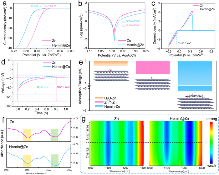
To investigate the protective effect of hemin molecules on the Zn anode, a linear sweep voltammetry (LSV) test was conducted. As illustrated in Fig. 2a, the Hemin@Zn anode shows a hydrogen evolution potential of ‒0.155 V relative to Zn/Zn2+, which is approximately 42 mV lower than that of bare Zn. Additionally, the corrosion resistance of the hemin coating was assessed using Tafel curves. The Hemin@Zn anode demonstrates a lower corrosion current of 2.0 mA/cm2 and a more positive corrosion potential of ‒0.97 V, in contrast to 4.3 mA/cm2 and ‒0.98 V for bare Zn (Fig. 2b). This suggests that hemin coating effectively decreases the corrosion rate and protects the Zn anode. The hydrogen evolution reaction influences the concentration of OH‒ around the anode, resulting in by-products that impact the reversibility of the Zn anode. Moreover, the zinc nucleation overpotential for the Hemin@Zn anode is 13 mV higher than that of the pure zinc anode (Fig. 2c), indicating a smaller nucleation radius for the Hemin@Zn electrode. The nucleation overpotentials for zinc deposition on bare zinc and Hemin@Zn were recorded at 102.2 mV and 80.6 mV, respectively (Fig. 2d). These results imply that hemin significantly contributes to reduce the nucleation barrier for zinc deposition and promote uniform zinc deposition.
Figure 2
Figure 2.
(a) LSV, (b) Tafel, (c) CV curves and (d) zinc deposition curves of the Hemin@Zn anode and the Zn anode. (e) Adsorption energy of the H2O molecule, Zn2+ and Hemin molecule on the Zn anode. (f, g) In-situ FTIR spectra of H3O+ and SO₄2- on the surface of Hemin@Zn anode and the Zn anode.
In order to gain a deeper understanding of the mechanism of hemin inhibiting the side reactions, DFT calculations were conducted to investigate the surface and interface behavior of the Hemin@Zn anode. As shown in Fig. 2e, the adsorption energies of water, zinc ions, and hemin on the zinc surface are −0.22, −0.59, and −5.52 eV respectively. Obviously, compared with free H2O molecules, hemin exhibits a much higher adsorption energy, indicating a stronger affinity for Zn. The adsorption energy between hemin and zinc is also higher than the values reported in the literature (Table S1 in Supporting information). It is believed that the preferential adsorption of hemin covering the active sites on the zinc surface to reduce the adsorption of H2O, which is beneficial for inhibiting hydrogen evolution and corrosion reactions. Moreover, the porphyrin ring and carboxyl groups of hemin can effectively separate Zn2+ from surrounding water molecules through strong chemical coordination, preventing the parallel reaction of water splitting and thus inhibiting dendrite formation [42-44].
In-situ Fourier transform infrared spectroscopy (in-situ FTIR) was utilized to continuously observe the changes in electrodes' interfacial substances. At a current density of 1 mA/cm2, a consistent current electrodeposition was observed in a zinc symmetric battery. As shown in Fig. 2f, before the deposition reaction, a distinct peak at 1267 cm−1 was identified, corresponding to the umbrella vibration of H3O+, indicating the presence of H3O+ species on the electrode surfaces. Additionally, a peak near 1100 cm−1 was associated with the S–O antisymmetric stretching vibration of SO42–. The absorbance intensity of Hemin@Zn was measured at −0.125, exceeding the bare Zn of −0.08, which suggests that Hemin@Zn has a greater affinity for the electrolyte. Similar findings were obtained from contact angle tests (Fig. S2 in Supporting information). The contact angle between Hemin@Zn and the ZnSO4 electrolyte was 44°, in contrast to 75° for the bare Zn anode, indicating that the bare Zn anode exhibits super-hydrophobicity. As the deposition time increased from 0 to 60 min, the absorbance of SO42− on the bare zinc electrode remained constant, while the SO42– signal at the Hemin@Zn electrode gradually increased, indicating that the concentration of SO₄2− on the zinc surface slowly increased over time (Fig. 2g). This indicates that the hemin interfacial layer helps to reduce the direct contact between the electrolyte and the zinc electrode during the deposition process, thus effectively reducing the occurrence of side reactions.
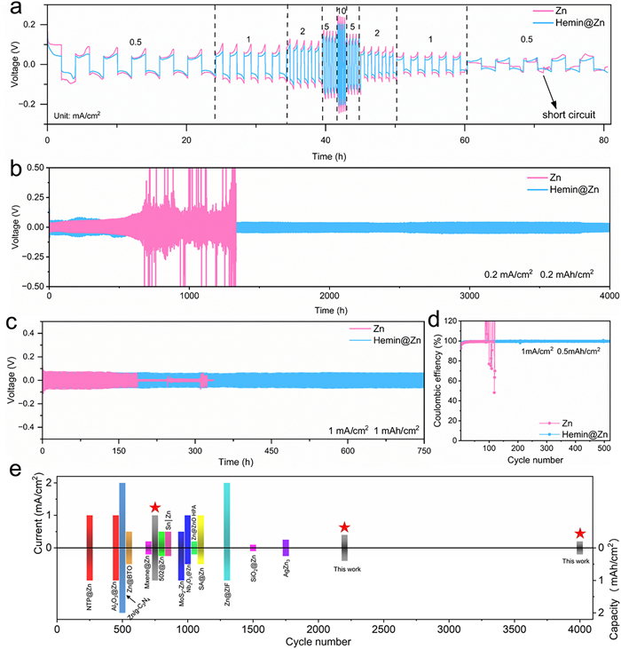
To evaluate the effect of the hemin interface on the Zn cycling stability behavior, the rate performance of the Zn and Hemin@Zn symmetric cells was investigated. As shown in Fig. 3a, as the current density increases, the polarization voltage of the Hemin@Zn symmetric cell increases and maintain stability during the cycling process (Fig. S3 in Supporting information). At lower current densities, it still shows good cycle stability. For the bare Zn anodes, there is a sharp decrease in voltage after 60 h of cycling, which is caused by short circuits resulting from the formation of zinc dendrites. Furthermore, the galvanostatic cycling performance of symmetric cells using bare Zn and Hemin@Zn (henceforth referred to as Zn//Zn and Hemin@Zn//Hemin@Zn, respectively) was determined at different current densities (Figs. 3b and c). Currently, the side reactions caused by solvent water are significantly amplified during cycling at low current density [45]. Therefore, we first checked the performance at 0.2 mA/cm2 with a capacity of 0.2 mAh/cm2. The bare Zn showed a significant increase in voltage after 500 h and a drastic fluctuation in voltage distribution at 700 h, and completely failed at 1110 h, attributed to the accumulation of "dead" zinc and harmful side reactions [46]. In contrast, Hemin@Zn shows a prolonged cycling life of up to 4000 h, which is nearly 5.7 times that of Zn without hemin decoration (Fig. 3b). When the symmetric cells were galvanostatic cycled at high current densities of 1 mA/cm2 with a capacity of 1 mAh/cm2, the bare Zn showed a short cycling life of 185 h. Correspondingly, Hemin@Zn showed a prolonged cycling life of 750 h, about 4 times that of the Zn symmetric batteries (Fig. 3c). In addition, at high current density of 0.4 mA/cm2 with a capacity of 0.4 mAh/cm2, Hemin@Zn symmetric battery exhibited exceptional cycle stability and a cycle life of > 2200 h (Fig. S4 in Supporting information). These results indicate the excellent cycling stability of the Hemin@Zn electrode across different current densities. Compared to previous interface modification strategies, the lifespan of Hemin@Zn is very competitive (Fig. 3e) [12,37,47-58]. Detailed information on the reported data is shown in Table S1. The CE can reflect the stability and reversibility of Zn striping/plating in the Zn//Cu cells. As revealed in Fig. 3d, the bare Zn//Cu cell only presents a short CE performance for 100 h, and then quickly show a sharp fluctuation to zero due to the unstable Zn plating/striping on Cu foil, which causes the failure of the cell. In comparison, the Hemin@Zn//Cu cell displays a gradually decreasing polarization voltage and a high average CE of 99.72% over 500 cycles (Figs. S5 and S6 in Supporting information), indicating an extraordinary steady electrochemical performance and side reaction inhibition capability of Hemin@Zn.
Figure 3
Figure 3.
(a) Rate performance of Zn||Zn and Hemin@Zn||Hemin@Zn symmetric cells. Plating/stripping cycle abilities of Zn symmetric cells at (b) 0.2 mA/cm2 with a capacity of 0.2 mAh/cm2, (c) 1 mA/cm2 with a capacity of 1 mAh/cm2. (d) CE of Zn//Cu asymmetric cells during long-term cycling. (e) Schematic illustration of cycling performance comparison in previous reports.
From the above electrochemical data and theoretical calculation results, it can be concluded that the hemin coating can improve the interfacial stability of zinc anode. In order to better understand the deposition during cycling, the surface morphologies of the Hemin@Zn and bare Zn electrodes were characterized by SEM after 150 cycles in symmetrical cells (1 mA/cm2, 1 mAh/cm2), and the results are shown in Figs. 4a-d. It can be seen that the bare Zn had an inhomogeneous and hilly surface (Fig. 4a). When observed at larger magnifications, vertical growth of zinc dendrite flakes about 10 µm in scale could be observed (Fig. 4b). These sharp, sheep-like and sharp dendrites with a large accessible surface can potentially promote parasitic reactions between Zn and the electrolyte [59]. In contrast, the Hemin@Zn surface showed a smooth and uniform morphology (Figs. 4c and d), indicating that the hemin interface layer contributed to a smaller nucleation radius and uniform nucleation and deposition. These results were confirmed by atomic force microscopy (AFM) detection. As shown in Fig. 4e, the surface of the Hemin@Zn anode was significantly smoother than that of the bare zinc anode.
Figure 4
Figure 4.
SEM images of (a, b) Zn foil and (c, d) Hemin@Zn anode after 150 cycles in asymmetric cells. (e) AFM images of cycled Zn electrodes and Hemin@Zn. (f) CA curves of Zn||Zn and Hemin@Zn||Hemin@Zn symmetric cells. (g) XRD patterns of symmetric cells after 150 cycles. (h) Schematic illustration of the mechanism of bare Zn anode and Hemin@Zn anode.
To investigate the different growth behaviors of zinc deposition on the zinc surface, chronoamperometry (CA) test was conducted, and the results are shown in Fig. 4f. When an overpotential of ‒150 mV is applied, the current intensity of bare Zn continues to increase within 300 s, indicating the irregular surface 2D diffusion and inhomogeneous Zn nucleation process on bare Zn. Consequently, Zn ions tend to adsorb along the surface of the tip or defect sites to minimize the surface energy of exposed zinc, which promotes the formation of dendrites. In contrast, the Hemin@Zn anode shows a stable and relatively low current within 50 s, indicating the 3D diffusion Zn nucleation process. With the help of hemin, due to its abundant nitrogen and oxygen functional groups, the aggregation and two-dimensional diffusion of Zn2+ are regulated during the deposition process, allowing for the uniform deposition of Zn2+ on the zinc anode. The 3D diffusion of Zn2+ ions dominate on the Hemin@Zn anode, resulting in uniform growth of Zn with suppressed dendrites. These results suggest that the hemin interface inhibits the 2D diffusion of Zn2+, promotes the uniform nucleation of Zn2+, and inhibits the formation of Zn dendrites.
The crystal structure of zinc after deposition was analyzed by XRD. As shown in Fig. 4g, the XRD pattern of bare Zn shows three new diffraction peaks at 8.3°, 16.3°, and 24.5° belonging to Zn4SO4(OH)6·5H2O (JCPDS No. 78–0246). The diffraction intensity of the by-products is nearly close to that of Zn, suggesting the occurrence of serious side reactions. Different from bare Zn, Hemin@Zn shows lower intensity of by-products than bare Zn, indicating that the side reactions are suppressed. These results are consistent with those of the in-situ FTIR results. The intensity of (002) diffraction peak of Hemin@Zn exhibits increases, indicating that the artificial interface layer promotes the growth of zinc crystal in the (002) direction. The processes of Zn deposition and cycling for bare Zn and Hemin@Zn electrodes are summarized as shown in Fig. 4h For the bare zinc anode, adverse reactions such as the hydrogen evolution reaction and metal corrosion occur at the zinc deposition interface. These reactions lead to the growth of zinc dendrites and the generation of by-products, ultimately causing the short circuit of the battery. In contrast, the Hemin@Zn electrode enables a flat deposition morphology and a stable interface, due to uniform zinc deposition and suppressed side reactions.
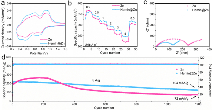
Since vanadium-based electrode materials are one of the promising candidates for aqueous zinc ions batteries, the NH4V4O10 cathode was selected to assemble a full cell for further confirming the feasibility and availability of the hemin artificial interface layer. The structure of NH4V4O10 was confirmed by XRD and SEM (Figs. S7 and S8 in Supporting information). As shown in Fig. 5a, the cell with the Hemin@Zn anode shows distinct redox peaks with a higher current in the CV curves compared to the cell with a bare Zn anode, indicating a higher electrochemical activity. Due to these advantages, the full cell with hemin@Zn anode delivers superior discharge capacities of 367, 342, 317, 296, 275, and 247 mAh/g at different current densities of 0.5–5 A/g (Fig. 5b), suggesting that the full cell with the Hemin@Zn anode has improved reversibility. Electrochemical impedance spectroscopy (EIS) analysis was performed on bare Zn//NH4V4O10 and Hemin@Zn//NH4V4O10 before and after cycling to understand the impact of the hemin coating on the resistance in the cell. The EIS spectrum in Fig. 5c shows that the impedance in the Hemin@Zn (127 Ω) battery is lower than that of the bare Zn foil (241 Ω), indicating a faster charge transfer rate. The Bode plots provide the details regarding the electrodes. As depicted in Fig. S9 (Supporting information), the |Z| value of Hemin@Zn is lower than that of pure zinc, indicating rapid ion diffusion on the electrode interface. Meanwhile the phase angle of Hemin@Zn is < 45°, indicating its cell interface is mainly charge-transfer controlled [60,61]. Moreover, the long-term cycling performance of the full cells was also investigated at a current density of 5 A/g in Fig. 5d. The capacity of full cell with Hemin@Zn electrode is at ~124 mAh/g with 53% capacity retention after 1200 cycles. In contrast, the capacity of the bare Zn//NH4V4O10 full cell drops to 72 mAh/g after 1200 cycles with capacity retention of 13%. The rapid capacity degradation is mainly attributed to the severe dendrite growth and side reactions during repeated cycling. These results indicate that hemin modification can not only enhance the durability of the zinc anode with electrolyte but also improve the stability of the full cell.
Figure 5
Figure 5.
(a) CV curves, (b) rate capability, (c) EIS and (d) long-term cycling performance of bare Zn//NH4V4O10 and Hemin@Zn//NH4V4O10 batteries.
In this study, Hemin was employed as an artificial interface layer with super strong adsorption energy to enhance the durability of zinc electrodes in zinc-ion batteries. The multi-functional hemin interface layer suppressed the side reactions between Zn and electrolyte as well as the hydrogen evolution reaction. Additionally, it guides uniform zinc deposition, which has been verified by electrochemical tests, XRD and SEM. As a result, symmetrical cells with Hemin@Zn delivered an impressive extended lifespan over 4000 h, paired with a remarkable average CE of 99.72% in Hemin@Zn//Cu asymmetrical cells. Moreover, the Hemin@Zn//NH4V4O10 full cell demonstrated enhanced capacities and improved cycling stability. This work indicates that the Hemin protection layer is a new choice for suppressing Zn dendrites, hydrogen evolution reaction, and side reactions.
Declaration of competing interest
The authors declare that they have no known competing financial interests or personal relationships that could have appeared to influence the work reported in this paper.
CRediT authorship contribution statement
Liang Wang: Writing – review & editing, Writing – original draft, Conceptualization. Weitao Li: Writing – original draft, Visualization, Investigation, Formal analysis, Data curation. Lei Zheng: Software, Methodology. Mengmin Jia: Resources, Funding acquisition. Dai-Huo Liu: . Dongmei Dai: Supervision, Resources, Project administration, Funding acquisition. Zhuangzhuang Zhang: Visualization, Validation, Resources. Chunyu Ma: Visualization, Investigation, Formal analysis, Data curation. Bao Wang: Supervision, Project administration, Funding acquisition, Data curation. Shengli Zhang: Visualization, Software, Methodology, Investigation, Formal analysis. Li Su: Writing – review & editing, Resources, Funding acquisition, Formal analysis. Bao Li: Supervision, Resources, Funding acquisition, Formal analysis, Data curation, Conceptualization.
Acknowledgments
This work was financially supported by the National Natural Science Foundation of China (No. 52372188), Natural Science Foundation of Henan (Nos. 242300421625, 252300421333), CAS Henan Industrial Technology Innovation & Incubation Center (No. 2024121), Key Scientific Research Project of Education Department of Henan Province (Nos. 22A150042, 23A150038, and 24A150019), 2023 Introduction of studying abroad talent program, the China Postdoctoral Science Foundation (No. 2019 M652546), Key Project of Science and Technology of Henan Province (No. 252102240007).
Supplementary materials
Supplementary material associated with this article can be found, in the online version, at doi:10.1016/j.cclet.2025.111458.
[1]
S.G. Chen, M.F. Zhang, P.M. Zou, et al., Energy Environ. Sci. 15 (2022) 1805–1839. doi: 10.1039/D2EE00004K
[2]
Y. Tao, Y. Cui, H. Wang, et al., Adv. Funct. Mater. 35 (2025) 2414805. doi: 10.1002/adfm.202414805
[3]
D. -H. Liu, M. Song, F. Xu, et al., Chem. Eur. J. 31 (2025) e202404600. doi: 10.1002/chem.202404600
Figure 1
(a) Fabrication schematic and optical pictures of Hemin@Zn. (b) Cross-sectional SEM image of the Hemin@Zn. (c) XRD patterns, (d, e) SEM images of bare Zn and Hemin@Zn anode. (f, g) High-resolution N 1s and Cl 2p spectra of bare Zn and Hemin@Zn. (h) EDS mapping images of Hemin@Zn.
Figure 2
(a) LSV, (b) Tafel, (c) CV curves and (d) zinc deposition curves of the Hemin@Zn anode and the Zn anode. (e) Adsorption energy of the H2O molecule, Zn2+ and Hemin molecule on the Zn anode. (f, g) In-situ FTIR spectra of H3O+ and SO₄2- on the surface of Hemin@Zn anode and the Zn anode.
Figure 3
(a) Rate performance of Zn||Zn and Hemin@Zn||Hemin@Zn symmetric cells. Plating/stripping cycle abilities of Zn symmetric cells at (b) 0.2 mA/cm2 with a capacity of 0.2 mAh/cm2, (c) 1 mA/cm2 with a capacity of 1 mAh/cm2. (d) CE of Zn//Cu asymmetric cells during long-term cycling. (e) Schematic illustration of cycling performance comparison in previous reports.
Figure 4
SEM images of (a, b) Zn foil and (c, d) Hemin@Zn anode after 150 cycles in asymmetric cells. (e) AFM images of cycled Zn electrodes and Hemin@Zn. (f) CA curves of Zn||Zn and Hemin@Zn||Hemin@Zn symmetric cells. (g) XRD patterns of symmetric cells after 150 cycles. (h) Schematic illustration of the mechanism of bare Zn anode and Hemin@Zn anode.


 DownLoad:


 下载:
下载:


 下载:
下载:
