Citation:
Qingkun Zhu, Yaodong Jin, Bao Zhang, Wei Liu, Haozhe Qin, Lei Ming, Xing Ou. Engineering a triplex ionic transport architecture for high ionic conductivity in solid-state lithium metal batteries[J]. Chinese Chemical Letters,
2026, 37(8): 111411.
doi:
10.1016/j.cclet.2025.111411
Engineering a triplex ionic transport architecture for high ionic conductivity in solid-state lithium metal batteries
English
Engineering a triplex ionic transport architecture for high ionic conductivity in solid-state lithium metal batteries
Engineering Research Center of the Ministry of Education for Advanced Battery Materials, School of Metallurgy and Environment, Central South University, Changsha 410083, China
b.
College of Physics Science and Technology, Yuzhong Campus, Lanzhou University, Lanzhou 730106, China
Received Date:
07 April 2025 Accepted Date:
06 June 2025 Revised Date:
28 May 2025 Available Online:
15 August 2026
Abstract:
A composite solid-state electrolyte with a triplex ionic transport architecture (TITA) was developed by integrating nanoscale fillers, short-chain crosslinkers and polymer matrix via solution casting and in situ photopolymerization. This structure creates efficient ion-conduction pathways, reduces ion aggregation, and enhances mechanical stability. As a result, the electrolyte achieves a high ionic conductivity of 7.36 × 10⁻⁴ S/cm and demonstrates excellent cycling performance when paired with an NCM622 cathode, showing great promise for solid-state lithium battery applications.
Liquid electrolytes in commercial lithium-ion batteries pose inherent risks of flammability and potential explosion [1–3]. In contrast, solid-state electrolytes (SSEs) provide a safer alternative, particularly when paired with lithium metal to achieve high energy densities [4–7]. SSEs are categorized into polymeric, inorganic, and composite types based on their composition. Among inorganic solid electrolytes, LLZTO [8,9] and LATP [10] oxides offer high stability but suffer from high interfacial resistance and complex fabrication. Sulfide-based electrolytes achieve high ionic conductivity but are chemically unstable, releasing toxic H2S in moisture, limiting practicality [11,12]. Unlike inorganic solid-state electrolytes, polymer solid-state electrolytes (PSEs) are characterized by low interfacial resistance, ease of manufacturing, and exceptional flexibility. Among various polymer matrices, polyethylene oxide (PEO) and polyacrylonitrile (PAN) have been extensively studied [13,14]. However, poly(vinylidene fluoride-co-hexafluoropropylene) (PVDF-HFP) stands out due to its high chemical and thermal stability, excellent mechanical strength, and the amorphous domains introduced by HFP units, which significantly enhance ionic conductivity [15–17]. Additionally, its high dielectric constant facilitates ion dissociation, promoting efficient lithium-ion transport. The unique combination of stability, processability, and electrochemical performance positions PVDF-HFP as a promising candidate for advanced composite electrolytes. Nonetheless, issues like inherently low ionic conductivity at room temperature and limited mechanical strength persist, requiring innovative strategies to overcome these limitations.
To address these challenges, incorporating fillers has proven effective in enhancing PSEs [18–21]. Common fillers include inert, non-conductive materials (e.g., Al2O3, SiO2) and fast ionic conductors (e.g., LLZTO, LATP). While fillers improve ionic conductivity and mechanical stability, issues remain, such as the non-conductivity of inert fillers, particle aggregation, reliance on polymer backbone motion for ion conduction, and side reactions or air instability of active fillers with lithium metal anodes [22]. In contrast, metal organic frameworks (MOFs) have gained recognition as a promising category of functional fillers, offering significant advantages for PSEs. They are formed through the self-assembly of metal clusters or ions with organic ligands, resulting in a highly ordered network structure that confers several key advantages. Firstly, their exceptionally high surface area enhances ion conduction by providing more active sites for ionic interaction. Additionally, the tunable porosity of MOFs enables selective ion transport, which not only promotes efficient ion diffusion but also contributes to improved electrolyte stability [22]. In addition, the strong adsorption capacity of MOFs enables them to capture impurities, thereby reducing side reactions that can otherwise degrade performance [23]. Consequently, this adsorption capability significantly enhances the long-term electrochemical stability of the system. Taken together, MOFs offer a versatile and effective solution for optimizing PSEs, addressing key performance limitations, and advancing the development of SSEs [24,25].
In this work, we propose a TITA-based electrolyte to overcome the inherent limitations of PVDF-HFP based electrolytes, especially low ionic conductivity at room temperature. To enhance ionic transport, zinc dimethylimidazole (ZIF8) nanoparticles were incorporated to form interconnected ion-conduction pathways and reduce ion aggregation, while a dual-network structure was established through poly(ethylene glycol) diacrylate (PEGDA) crosslinking. The synergy of ZIF8 and PEGDA within the TITA provides abundant active sites for efficient lithium-ion transport, while the enhanced mechanical stability ensures structural integrity during long cycling. As a result, the TITA-based electrolyte exhibits outstanding performance, including an ionic conductivity of 7.36 × 10⁻⁴ S/cm, an electrochemical stability window of 4.9 V (vs. Li+/Li), and remarkable cycling stability when combined with NCM622 cathode, a brief comparison with recently reported composite solid-state electrolytes is provided in Table S1 (Supporting information).
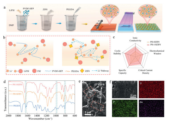
The composite electrolyte developed in this study was prepared by solution casting and in-situ photopolymerization, using a mixture of DMF, PVDF-HFP, LiFSI, ZIF8 and PEGDA, which was uniformly coated onto a glass substrate (Fig. 1a). The digital photographs and thickness of electrolyte membranes are shown in Figs. S1 and S2 (Supporting information). ZIF8, characterized by its porous structure and abundant functional groups, adsorbs anionic species to release more free lithium ions, while also providing additional ion transport pathways. Moreover, PEGDA undergoes crosslinking during photopolymerization, generating more ion transport pathways and binding sites (Fig. 1b). As a result, the constructed TITA composite electrolyte demonstrates outstanding performance, including high ionic conductivity, a wide electrochemical stability window, excellent cycling stability, superior discharge specific capacity, and enhanced compatibility with lithium metal (Fig. 1c).
Figure 1
Figure 1.
(a) Schematic representation of the fabrication process for the PH-10ZIF8 composite electrolyte. (b) Illustration of the modified ionic conduction mechanism. (c) Performance comparison between PH-0ZIF8 and PH-10ZIF8. (d) Fourier transform infrared (FTIR) spectra of PH-0ZIF8, PH-10ZIF8 and PEGDA. (e) The distribution of ZIF8 in PH-10ZIF8. (f) Elemental mapping of S, F and Zn.
As illustrated in Fig. 1d, the characteristic peaks at 1640, 984, and 808 cm−1 correspond to the stretching vibration, out-of-plane bending vibration, and deformation vibration absorption of (C=C) bonds in the PEGDA monomer, respectively [26,27]. After polymerization, these characteristic peaks of unsaturated alkenes nearly disappeared, confirming the polymerization of PEGDA and the formation of a dual-network structure with PVDF-HFP [28,29]. As shown in Fig. 1e, based on the SEM image of ZIF8 at the nanoscale (Fig. S3 in Supporting information), ZIF8 is uniformly dispersed on the membrane. Additionally, the distribution of Zn in Fig. 1f further illustrates the spatial distribution of ZIF8. Moreover, the addition of ZIF8 endows the TITA with enhanced mechanical properties, as evidenced by stress–strain curves in Fig. S4 (Supporting information).
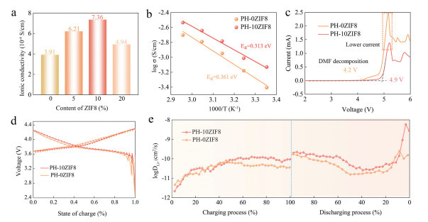
The inherently low ionic conductivity of polymer electrolytes remains their primary limitation [30]. To address this, varying amounts of ZIF8 (5%, 10%, and 20% by weight) were incorporated into PVDF-HFP, forming the TITA with PEGDA-based crosslinking. Impedance measurements across different temperatures revealed the ionic conductivities shown in Fig. 2a. Among these, the PH-10ZIF8 sample (10% ZIF8) exhibited the highest ionic conductivity of 7.36 × 10⁻⁴ S/cm. This enhancement stems from the porous structure and functional groups of ZIF8 in the TITA, which provide interconnected ionic conduction pathways. Meanwhile, the dual network constructed by PEGDA reduces the dependence of ion transportation on the movement of the polymer chain segments. However, excessive ZIF8 loading reduced conductivity, likely due to filler agglomeration causing transport blockage [31]. Based on these results, PH-0ZIF8 (0% ZIF8) and PH-10ZIF8 were selected for further comparative analysis. Fig. S5 (Supporting information) displays the EIS spectra of PH-0ZIF8 and PH-10ZIF8 across different temperatures, with their Arrhenius plots (Fig. 2b). The activation energies were calculated as 0.361 and 0.313 eV for PH-0ZIF8 and PH-10ZIF8, respectively, indicating improved lithium-ion transportation in PH-10ZIF8. Furthermore, the incorporation of ZIF8 facilitates Lewis acid–base interactions between its functional groups and FSI⁻ anions, which weakens the coordination between Li+ and FSI⁻ (Fig. S6 in Supporting information). This disruption of contact ion pairs enhances lithium-ion dissociation and leads to increased lithium-ion transference numbers of 0.25 and 0.43 for PH-0ZIF8 and PH-10ZIF8, respectively, as determined from the AC impedance spectra in Fig. S7 (Supporting information). LSV confirmed that the TITA effectively suppressed DMF decomposition and extended the electrochemical stability window from 4.7 V to 4.9 V (Fig. 2c) [31]. Notably, PH-10ZIF8 exhibits a lower oxidation current, suggesting mitigated decomposition reactions, which correlates with the improved high-voltage stability of the electrolyte. These results underscore the synergistic roles of ZIF8 and PEGDA in achieving superior ionic conductivity, reducing activation energy and enhancing high-voltage stability.
Figure 2
Figure 2.
(a) Ionic conductivities of electrolytes with varying ZIF8 contents. (b) Arrhenius plots of ionic conductivity. (c) Electrochemical stability windows. (d) GITT voltage profiles. (e) Lithium-ion diffusion coefficients for PH-0ZIF8 and PH-10ZIF8.
Fig. 2d illustrates the galvanostatic intermittent titration voltage (GITT) profiles of button cells utilizing PH-0ZIF8 and PH-10ZIF8 electrolytes with NCM622 cathode and lithium metal anode. PH-0ZIF8 exhibits significantly higher polarization compared to PH-10ZIF8. The calculated lithium-ion diffusion coefficients in the NCM622 cathode, as depicted in Fig. 2e, reveal a notable enhancement with the incorporation of ZIF8. This improvement highlights the kinetic advantages of PH-10ZIF8, indicating its superior capability to sustain excellent performance under high current density conditions.
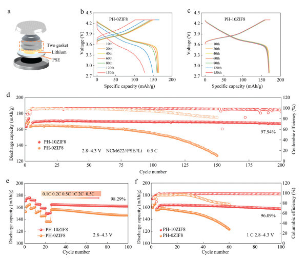
To evaluate the enhanced performance of ZIF8-incorporated electrolytes in lithium metal batteries, NCM622//PSE//Li coin cells were assembled. As shown in Fig. 3a, two gaskets were introduced to improve the interfacial contact between electrodes and PSE. Figs. 3b and c present the charge-discharge voltage profiles of PH-0ZIF8 and PH-10ZIF8 at 0.5 C rate over multiple cycles. In comparison, PH-10ZIF8 exhibits a highly stable voltage plateau throughout the charge-discharge process, accompanied by significantly reduced polarization, indicating superior charge-discharge kinetics. Additionally, the comparison of dQ/dV curves further verify the superior long-term stability and electrochemical reversibility of PH-10ZIF8 (Fig. S8 in Supporting information). These improvements are attributed to the synergistic effects of the TITA, where the porous ZIF8 provides interconnected ion-conduction pathways and mitigates ion aggregation, while the PEGDA contributes to mechanical stability and facilitates uniform ion distribution. This unique combination optimizes ion transport and enhances overall electrochemical performance, significantly boosting the cycling and rate capabilities of the battery. Regarding long-cycle performance at 0.5 C, as shown in Fig. 3d, the PH-10ZIF8 cell demonstrates excellent stability, retaining a discharge specific capacity of 167.2 mAh/g and a capacity retention of 97.74% after 200 cycles. In stark contrast, the cell without ZIF8 undergoes significant capacity decay, with its capacity drastically dropping after 150 cycles. This superior cycling performance is a direct result of the TITA, which mitigates interface degradation and supports efficient ion transport over extended cycling. Moreover, the PH-10ZIF8 cell achieves remarkable rate capability, as evidenced by the voltage-specific capacity profiles at different current densities (Fig. S9 in Supporting information). The smoother voltage plateau and reduced polarization observed in the PH-10ZIF8 cell clearly reflect improved ion transport kinetics, which contribute to enhanced electrochemical performance. As illustrated in Fig. 3e, the PH-10ZIF8 cell exhibits outstanding rate performance with discharge specific capacities of 175, 172, 165, 158, and 150 mAh/g at 0.1, 0.2, 0.5, 1.0 and 2.0 C, respectively. Furthermore, after 100 cycles, when rate returned to 0.5 C, the cell retained 98.29% of its capacity, demonstrating exceptional cycling stability. Similarly, the long cycling performance of both electrolytes at higher rate of 1 C was evaluated. As depicted in Fig. 3f, the PH-10ZIF8 cell shows significantly enhanced cycling stability, achieving a discharge specific capacity of 157.2 mAh/g with a capacity retention of 96.09% after 100 cycles. By contrast, the PH-0ZIF8 cell experiences substantial capacity degradation, with its discharge specific capacity dropping to 123.3 mAh/g after just 60 cycles. This enhanced performance under high-current conditions further highlights the advantages of the TITA, which provides stable ion-conduction pathways and suppresses interfacial degradation, enabling consistent operation even at elevated rates.
Figure 3
Figure 3.
Electrochemical performance of NCM622||PH-0/10ZIF8||Li coin cells at room temperature. (a) Schematic illustration of the coin cell assembly. Voltage-specific capacity profiles at 0.5 C for (b) PH-0ZIF8 and (c) PH-10ZIF8. (d) Cycling performance at 0.5 C. (e) Rate performance comparison. (f) Cycling performance at 1 C.
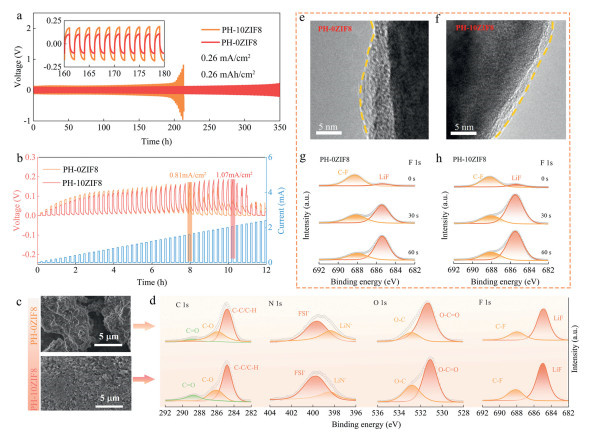
To verify the improvement of the stability between lithium anode and electrolyte by the addition of ZIF8, Li symmetric cells were fabricated. At a current density of 0.26 mA/cm2, Li||PH-10ZIF8||Li symmetric cell exhibits lower polarization voltage and longer cycle lifespan (Fig. 4a). This enhanced stability is attributed to the TITA, in which the ZIF8 mitigates dendrite growth by promoting uniform ion distribution, and the robust polymer network provides mechanical resistance to dendrite penetration. Additionally, critical current density (CCD), a key metric for assessing the ability of SSEs to suppress the growth of lithium dendrite, increased from 0.81 mA/cm2 for PH-0ZIF8 to 1.07 mA/cm2 for PH-10ZIF8 (Fig. 4b). This improvement underscores the effectiveness of the TITA in reducing dendrite formation, facilitated by the porous framework of ZIF8 and the mechanical reinforcement of dual-network. SEM images of the lithium metal anode after 50 cycles (Fig. 4c) further illustrate these effects. The lithium anode in the PH-0ZIF8 cell developed significant roughness and cracks, while the anode in the PH-10ZIF8 cell appeared much smoother. This improvement can be attributed to the TITA, which promotes uniform lithium-ion transport, reduces localized deposition and enhances interfacial stability with lithium metal. Moreover, the XPS spectra of the lithium metal anode after cycling are presented in Fig. 4d. In the C 1s XPS spectrum, peaks observed at 284.8, 286.3, and 288.5 eV correspond to C-C, C-O and C=O, respectively [32]. In the N 1s XPS spectra, an increase in the integral intensity of the FSI− of PH-10ZIF8 at 399.5 eV can be seen [24,32], suggesting more lithium salt dissociation. The O 1s XPS spectrum is divided into two peaks at 531.2 eV (O-C=O) and 533.0 eV (C-O) [33]. In the F 1s XPS spectrum, the peaks at 684.8 and 688.4 eV are ascribed to LiF and C-F, respectively [34]. LiF is an important SEI constituent that suppresses dendrite growth and side reactions at the electrode-electrolyte interface [35]. After the incorporation of ZIF8, the intensity of LiF peaks increased.
Figure 4
Figure 4.
(a) Voltage curves of Li symmetric cells assembled with PH-0ZIF8 and PH-10ZIF8 at a current density of 0.26 mA/cm2. (b) Critical current density (CCD) of Li||Li symmetric cells assembled with PH-0ZIF8 and PH-10ZIF8. (c) SEM images of the lithium metal anode surface after 50 cycles. (d) XPS spectra of C 1s, N 1s, O 1s, and F 1s for the lithium metal anode after cycling. CEI of the full cell after cycling with (e) PH-0ZIF8 and (f) PH-10ZIF8. Etched XPS of F 1s for cathode after 50 cycles: (g) PH-0ZIF8 and (h) PH-10ZIF8.
The cathode electrolyte interface (CEI) after 50 cycles of full cell operation is analyzed, with the CEI morphology observed using TEM shown in Figs. 4e and f. Compared to PH-0ZIF8, PH-10ZIF8 cell exhibits a thicker and more homogeneous CEI layer at the interface with the cathode, indicating fewer side reactions. The chemical compositions of the CEIs are further examined using ion-etched XPS. As shown in Figs. 4g and h, the intensity of LiF increases with prolonged etching time, and PH-10ZIF8 exhibits a higher LiF content. The increased LiF concentration is closely associated with the enhanced electrochemical performance of the solid-state battery utilizing PH-10ZIF8, as LiF demonstrates outstanding morphing mobility, self-healing capabilities, excellent antioxidant properties, and improves the stability of electrolyte at high potentials [33,36]. Furthermore, XPS results for C 1s at varying etching times, presented in Fig. S10 (Supporting information), reveal that the peak intensity for PH-10ZIF8 is lower after etching, further substantiating its thinner CEI layer and reduced side reactions.
In conclusion, the TITA-based composite solid-state electrolyte demonstrates outstanding ionic conductivity and a wide electrochemical stability window at room temperature. These remarkable properties stem from the synergistic effects of ZIF8 and PEGDA within the TITA. The porous structure and functional groups of ZIF8 provide interconnected ion-conduction pathways and mitigate ion aggregation, while its integration with PEGDA enhances mechanical stability. When coupled with an NCM622 cathode, the composite electrolyte achieves exceptional cycling stability, maintaining a capacity retention of 97.94% after 200 cycles at 0.5 C, and exhibits excellent interfacial stability with the lithium metal anode. This work highlights the TITA as a promising design for advanced SSEs.
Declaration of competing interest
The authors declare that they have no known competing financial interests or personal relationships that could have appeared to influence the work reported in this paper.
This work was financially supported by Guizhou Provincial Major Scientific and Technological Program (No. Qian Kehe Major Special Projects [2024]019), the Science and Technology Innovation Program of Hunan Province (No. 2023RC3041).
Supplementary materials
Supplementary material associated with this article can be found, in the online version, at doi:10.1016/j.cclet.2025.111411.
Figure 1
(a) Schematic representation of the fabrication process for the PH-10ZIF8 composite electrolyte. (b) Illustration of the modified ionic conduction mechanism. (c) Performance comparison between PH-0ZIF8 and PH-10ZIF8. (d) Fourier transform infrared (FTIR) spectra of PH-0ZIF8, PH-10ZIF8 and PEGDA. (e) The distribution of ZIF8 in PH-10ZIF8. (f) Elemental mapping of S, F and Zn.
Figure 2
(a) Ionic conductivities of electrolytes with varying ZIF8 contents. (b) Arrhenius plots of ionic conductivity. (c) Electrochemical stability windows. (d) GITT voltage profiles. (e) Lithium-ion diffusion coefficients for PH-0ZIF8 and PH-10ZIF8.
Figure 3
Electrochemical performance of NCM622||PH-0/10ZIF8||Li coin cells at room temperature. (a) Schematic illustration of the coin cell assembly. Voltage-specific capacity profiles at 0.5 C for (b) PH-0ZIF8 and (c) PH-10ZIF8. (d) Cycling performance at 0.5 C. (e) Rate performance comparison. (f) Cycling performance at 1 C.
Figure 4
(a) Voltage curves of Li symmetric cells assembled with PH-0ZIF8 and PH-10ZIF8 at a current density of 0.26 mA/cm2. (b) Critical current density (CCD) of Li||Li symmetric cells assembled with PH-0ZIF8 and PH-10ZIF8. (c) SEM images of the lithium metal anode surface after 50 cycles. (d) XPS spectra of C 1s, N 1s, O 1s, and F 1s for the lithium metal anode after cycling. CEI of the full cell after cycling with (e) PH-0ZIF8 and (f) PH-10ZIF8. Etched XPS of F 1s for cathode after 50 cycles: (g) PH-0ZIF8 and (h) PH-10ZIF8.


 DownLoad:

 下载:
下载:


 下载:
下载:

