Citation:
Peining Zhu, Xi Guo, Qinqin Yu, Zuyong Wang, Xiangxiao Lei, Zhiwei Zhu, Juan Du, Xiaojia Zhang, Yuan-Li Ding. Design strategies of Si-based anode for solid-state batteries[J]. Chinese Chemical Letters,
2025, 36(9): 111383.
doi:
10.1016/j.cclet.2025.111383
Design strategies of Si-based anode for solid-state batteries
English
Design strategies of Si-based anode for solid-state batteries
Received Date:
27 January 2025 Accepted Date:
28 May 2025 Revised Date:
21 May 2025 Available Online:
15 September 2025
Abstract:
Solid-state lithium-ion batteries (SSLIBs) offer significant advantages over traditional liquid-electrolyte-based batteries, including improved safety, higher energy density, and better thermal stability. Among various anode materials, silicon (Si)-based anodes have attracted significant attention due to their ultrahigh theoretical capacity (~4200 mAh/g) and abundant resources. However, widespread adoption of Si-based anodes in SSLIBs is still restricted by some critical challenges such as severe volume expansion, low electronic and ionic conductivity, high interfacial impedance, and low initial Coulombic efficiency (ICE). This review mainly focuses on the design strategies of Si-based anode for SSLIBs at the material, electrode and cell levels including nanostructuring, Si alloys, Si-carbon composites, conductive additives, advanced binder, external pressure, electrolyte infiltration, and prelithiation. The insights provided here aim to inspire future research and accelerate commercialization of high-performance Si-based anodes in next-generation SSLIBs.
The concept of solid-state lithium-ion batteries (SSLIBs) originated as an evolution of conventional liquid-electrolyte-based lithium-ion batteries (LIBs), with the aim of addressing the safety concerns, stability issues, and energy density limitations associated with liquid electrolytes [1–3]. SSLIBs offer several key advantages over traditional LIBs, particularly in terms of safety, energy density, and thermal stability [4–6]. The replacement of flammable liquid electrolytes with solid-state electrolytes (SSEs) significantly reduces the risk of battery fires and explosions, making SSLIBs a safer alternative for various applications, especially in electric vehicles (EVs) and portable electronics [7,8]. Meanwhile, SSEs enable the use of lithium (Li) metal anodes, which have a higher specific capacity (3860 mAh/g) than traditional graphite anodes (372 mAh/g). This leads to a significant improvement in energy density, enabling long-lasting batteries with higher power outputs [9]. Moreover, SSEs exhibit better thermal stability than liquid electrolytes, allowing SSLIBs to operate under a broader range of temperatures. Additionally, SSEs are less prone to chemical degradation, which enhances the overall longevity and cycle life of the battery [10–13].
However, despite these advantages, SSEs still face challenges related to side reactions and the formation of solid electrolyte interphase (SEI). These reactions occur at the interface between the SSE and the anode, particularly with materials like Si, which undergo large volume changes during cycling. The formation of an SEI is crucial for protecting the anode and facilitating ion transport, but in SSEs, the SEI is usually unstable and prone to cracking due to large mechanical stress. This instability leads to continuous consumption of Li, increased interfacial resistance, and degradation of the battery's performance over time. Thus, while SSEs hold significant promise, addressing these interfacial challenges remains a key area for improving the performance and longevity of solid-state batteries (SSBs).
The study of anodes in SSLIBs is of paramount importance due to its direct impact on battery performance, including energy density, cycling stability, and safety [14,15]. In SSLIBs, the choice of anode material is critical, as it must be compatible with SSEs, offer good ionic conductivity, and maintain stability over numerous charge-discharge cycles [16]. Graphite is a widely studied anode material due to its well-known lithium-intercalation mechanism and electrochemical stability. It exhibits low volume expansion during Li insertion and extraction, which contributes to excellent cycling stability. However, its relatively low capacity (~372 mAh/g) limits the energy density of full cells. Additionally, graphite's interface with SSEs usually suffers from high interfacial resistance, resulting in unsatisfactory overall performance [17–20].
Li metal has an extremely high theoretical capacity (3860 mAh/g) and low electrochemical potential, making it an attractive anode material for high-energy SSLIBs [21,22]. However, Li metal faces a critical challenge of dendrite formation during cycling, which can also pierce the SSE and cause short circuits or even thermal runaway [23,24]. In recent years, a large amount of research has focused on stabilizing the Li-SSE interface and preventing dendrite growth using protective coatings or alloying with other metals [25–28]. In addition, the use of Li metal anode suffers from a poor interface chemical stability issue for sulfide-based SSEs as well.
Compared to Li metal anode, alloy-based materials have attracted considerable interests as anode for SSLIBs owing to lower dendrite risks and higher specific capacities [29]. For example, tin (Sn) [30,31], aluminum (Al) [32,33], Ge, Sb, P, In, and lithium-tin (Li-Sn) alloys [34–39], are being explored for their ability to offer higher capacities than graphite while also reducing some of the risks associated with pure Li metal anodes. Tin, for instance, possesses a higher theoretical capacity (~994 mAh/g) than graphite, but it still suffers from large volume changes during cycling. Aluminum anodes have a relatively lower capacity than tin but are favored for cycling stability.
In contrast to the above alloying anodes, Si-based materials show attractive merits including high theoretical capacity (up to 4200 mAh/g), lower dendrite risk, earth-abundant resources, low cost and relatively environmental benign, endowing them with a promising anode candidate for SSLIBs [40–44].
However, Si anode still suffers from several critical challenges for practical applications in SSLIBs: (1) Volume expansion: Si usually undergoes a large volume expansion up to 300% during lithiation, leading to particle fracture, electrode degradation, and a loss of electrical contact within the electrode (Fig. 1a), and ultimately poor cycling stability [45,46]. (2) Low electronic and ionic conductivity: Si anodes have inherently low electronic conductivity and, when combined with SSEs, the ionic conductivity of the system is also limited. This hampers fast electron and ion transport, restricting the overall rate capability and efficiency of the battery [47,48]. (3) High interfacial impedance: the fundamental mechanism of high interfacial resistance in Si anodes in SSBs is primarily attributed to the poor contact and instability of the SEI layer during cycling. Si anodes undergo significant volume expansion during lithiation, causing mechanical stress at the Si-electrolyte interface. This stress leads to the formation of cracks and delamination of the SEI, disrupting its integrity, as illustrated in Fig. 1a. As a result, the SEI becomes less effective in protecting the anode surface and facilitating efficient ion transport, leading to an increase in interfacial resistance. Moreover, the mismatch in mechanical properties between Si and the solid-state electrolyte further exacerbates the poor interface stability, making it difficult for the SEI to withstand the volume changes of Si and maintain a low-resistance pathway for Li-ion conduction [49,50]. (4) Low ICE: The low ICE of Si anodes in SSBs is primarily caused by the irreversible Li consumption during the formation of the SEI layer. When Si anode is first cycled, a substantial amount of Li is irreversibly consumed to form the SEI, which accounts for the initial capacity loss. Due to the large volume changes of Si during lithiation, the SEI is prone to cracking and reformation, consuming additional Li and further reducing the ICE [51,52].
Figure 1
Figure 1.
(a) Schematic diagram illustrating the volume expansion of Si anode and the corresponding issues of particle fracture, degraded contact, and high interfacial impedance. (b) Schematic diagram illustrating the major issues faced by Si-based anodes in SSLIBs, along with the corresponding optimization strategies at the material, electrode and cell levels.
To address the above four key challenges of Si anodes in SSLIBs, a range of strategies have been proposed. (1) The significant issue of volume expansion during lithiation has driven research into nanostructuring Si materials [53,54], which helps to reduce internal stress and prevent mechanical failure. Additionally, silicon oxides (SiOx) and Si-metal alloys have been extensively studied as they provide more stable frameworks, reducing the impact of volume changes and improving mechanical resilience [55–58]. (2) To solve the problem of low electronic and ionic conductivity, researchers have turned to Si-carbon composites [59–61], which integrate conductive carbon materials to enhance electron transport, and conductive additives [62,63], which further boost both electronic and ionic conductivity by creating an efficient conductive network within the electrode. (3) The challenge of interfacial impedance is being tackled through the development of new binders [64–66], maintaining stable contact between Si anode and SSE with external pressure [67–69], and infiltration of electrolytes into the Si anode [70,71]. These approaches reduce interfacial resistance by improving solid-solid contact and facilitating ion transport [72]. (4) Lastly, to address low ICE, prelithiation has been widely explored. This technique introduces Li into the anode prior to cycling, thereby compensating for the initial irreversible Li loss and improving energy efficiency. Each of these strategies is crucial for addressing the inherent challenges of Si anodes and making them viable for next-generation SSLIBs [73,74].
Herein, we present a comprehensive review of strategies aimed at addressing the four critical challenges faced by Si anodes in SSLIBs, covering approaches at the material, electrode, and cell levels. As illustrated in Fig. 1b, this review systematically evaluates: (1) Material-level strategies, including solutions to mitigate volume expansion and enhance the electronic and ionic conductivity of Si-based materials; (2) Electrode-level strategies, such as prelithiation, electrolyte infiltration, advanced binders, and conductive additives, which improve structural integrity and electrochemical performance; (3) Cell-level strategies, such as external pressure applications, to effectively address interfacial impedance challenges. This review offers a holistic and systematic analysis of the optimization strategies currently being explored for Si-based anodes, providing a detailed discussion of their mechanisms, advantages, and limitations (strategies with typical examples are presented in Table 1). By covering most of the state-of-the-art strategies, this work serves as a valuable resource for researchers aiming to develop advanced Si-based anodes. We believe this review will offer critical insights and practical guidance for accelerating the development and commercialization of Si-based anodes for next-generation SSLIBs.
Table 1
Table 1.
Strategies aimed at addressing the key challenges of Si-based anodes in SSLIBs.
The volume expansion of Si-based anode occurs primarily during lithiation process [75,76]. As Si accommodates a large number of Li ions, the lattice usually expands upon alloying reaction, leading to a volume change up to 300%. This expansion is much larger than that observed in conventional graphite anodes. The root cause of this expansion is the alloying reaction between Si and Li, which forms various Li-Si phases (e.g., Li15Si4). When Li enters the Si structure, the crystalline structure of Si is disrupted, resulting in the formation of amorphous or crystalline Li-Si alloys. This leads to mechanical stress within the material, causing cracking, particle pulverization, and final loss of electrical contact between active particles and current collector [77]. These effects can lead to rapid capacity fade and poor cycling stability, which are key barriers to the widespread use of Si anodes in SSLIBs [78]. Various strategies such as nanostructuring and composite formation are actively being researched to accommodate the volume changes and maintain the structural integrity of the Si-based anodes throughout the battery's lifecycle.
2.1
Nanostructuring
Nanostructuring is an effective strategy for mitigating the severe volume expansion that occurs in Si-based anodes during lithiation in SSLIBs, and the key mechanism for this is the reduction in the size of the Si material [79]. When Si is engineered into nano-scale structures, such as nanoparticles, nanowires, or porous nanostructures, the smaller size allows for more uniform stress distribution during the volume expansion and contraction that happens with Li insertion and extraction. Because nanostructured Si has higher surface area to volume ratio and extra pore space between particles or in porous structure, it can better adapt to large volume changes without cracking, thus minimizing mechanical damage and maintaining electronic contact between active materials and current collectors, as well as enhancing its interaction with SSEs [80]. At the same time, nanostructured Si significantly improves Li-ion diffusion pathways, leading to better charge/discharge rates and enhanced cycling stability, further improving the overall battery performance [81,82].
2.1.1
Silicon nanoparticles
The particle size of Si materials has long been a focal point in research on liquid-electrolyte-based LIBs and continues to play a crucial role in SSLIBs [83,84]. In liquid-electrolyte systems, downsizing bulk Si to the nanoscale has proven to be effective in minimizing crack propagation by reducing the strain energy accumulated during electrochemical reactions. This approach significantly enhances the structural stability and prolongs the cycling life of the anodes [85,86]. Drawing from these insights, similar strategies are now being applied to Si materials in SSLIBs, with particle size optimization emerging as a key research direction. Researchers are exploring how nanoscale Si can better accommodate the inherent mechanical stresses in solid-state systems, thereby improving both battery performance and longevity in these next-generation energy storage technologies.
In 2010, Trevey et al. conducted a study comparing the electrochemical performance of nano-silicon (50–100 nm) and bulk Si (1–5 µm) as anodes in SSLIBs, using an SSE composed of 77.5Li2S-22.5P2S5 (mol%). The results demonstrated that Si nanoparticles significantly outperformed micron-sized Si particles, exhibiting much higher capacity and improved cycling stability. The enhanced performance was attributed to the smaller particle size of nano-silicon mitigating the mechanical degradation typically caused by volume expansion during cycling [63]. Dunlap et al. observed a similar trend in a coal-tar-pitch derived Si-C composite anode, where the composite anode containing 50 nm Si particles demonstrated superior performance compared to those constructed with micron-sized Si particles (1–3 µm). The nano-Si anodes showed better first cycle capacity, higher coulombic efficiency (CE), improved capacity retention, and more compact electrode structures with fewer cracks contributing to better electrochemical stability. In contrast, the electrodes with micro-sized Si exhibited noticeable voids and separated interfaces after cycling, which hindered electron and Li-ion transport through the electrode, leading to increased cell resistance and degraded performance [87]. Similarly, Kim's group demonstrated that nanoscale Si in graphite composite electrodes showed improved specific capacities and better performance at higher current densities (0.5 C rate), outperforming those with micro-sized Si [88]. The improvement was attributed to a more uniform distribution of nanoscale Si in the graphite compared to micro-sized particles, shortening the effective diffusion pathway in the electrode. In order to estimate the contact area as a function of Si particle size, virtual three-dimensional (3D) structures of graphite-silicon diffusion-dependent anodes with different Si particle sizes were constructed (Fig. 2a). These structures were designed with consistent parameters, including a loading level of 5.68 mg/cm2 and a thickness of 28.5 µm. Utilizing these digital twin models, the contact area was quantitatively assessed and summarized in Fig. 2b, the incorporation of Si nanoparticles significantly increased the contact area with graphite particles from 1.732 × 10⁻⁹ m2 to 5.255 × 10⁻⁹ m2, representing an approximate 200% enhancement. When converted to the ratio of the contact area relative to the total surface area of the graphite particles, it was found that Si nanoparticles covered 78.2% of the entire graphite surface, while microparticles only covered 25.8%.
Figure 2
Figure 2.
(a) Digital twin-driven 3D structures of graphite-silicon electrodes with Si microparticles (µ-Si, left) and Si nanoparticles (n-Si, right). (b) Changes in contact area between Si and graphite as a function of Si particle size, presented both in absolute values (m2) and as a relative ratio (%). (c, d) Li-ion concentrations within the graphite phase (left) and Si phase (middle), along with Li-ion diffusion fluxes in the Si phase(right) for (c) Gr/µ-Si and (d) Gr/n-Si electrodes, measured at 0.01 V (vs. Li/Li+) during charging at 0.5 C-rate and 60 ℃. Reproduced with permission [88]. Copyright 2021, Wiley. (e) A schematic representation of a 99.9 wt% microsilicon (µSi) electrode in an all-solid-state battery (ASSB) full cell. During lithiation, a passivating SEI forms between the µSi and the solid-state electrolyte (SSE), followed by the lithiation of µ-Si particles near the interface. The reactive Li-Si then interacts with surrounding Si particles, and the reaction propagates, forming a densified Li-Si layer across the electrode. Reproduced with permission [96]. Copyright 2021, The American Association for the Advancement of Science.
To theoretically evaluate the impact of this enhanced contact area on electrochemical performance, the 3D structures were utilized for electrochemical simulations, coupled with a Li metal electrode and a Li6PS5Cl (LPSCl) solid electrolyte layer. Figs. 2c and d depict the Li-ion concentrations in the graphite phase (left) and the Si phase (middle) for graphite-silicon electrodes using Si microparticles and nanoparticles, respectively, at the final moment at 0.01 V (versus Li/Li+) during discharge at a 0.5 C-rate. The simulations revealed a substantial increase in Li-ion concentration within both the graphite and Si phases when utilizing Si nanoparticles. This suggests that the expanded interfacial area facilitates interdiffusion, allowing for enhanced Li-ion transport and reduced diffusion tortuosity within the electrode. Consequently, active material particles, even those located near the current collector, can efficiently accept the abundant Li ions available through the broadened Li-ion pathways. Therefore, these simulation results indicate that controlling particle size to increase contact area significantly improves Li-ion transport throughout the electrode.
Most recently, Li et al. conducted a systematically study on the effect of Si particle size in SSBs by investigating Si particles ranging from 30 nm to 1000 nm [89]. The SSLIBs were assembled with Si anodes of varying particle sizes, and the 200 nm Si anode exhibited the highest ICE of 78.37% and superior cycling stability compared to the batteries using 30 nm and 1000 nm Si particles. The sub-micron Si particles (200 nm) provided a moderate tap density and controlled expansion, facilitating the densification of the electrode and improving ion conduction. This led to a more uniform de-lithiation process, minimizing the formation of cracks and large voids, and ensuring the structural stability of the electrode. This behavior contrasts with Si anodes in liquid batteries, where smaller particle sizes generally correlate with better electrochemical and long-cycle performance, as previously reported in earlier studies [90].
However, in the comparative study of Si nanoparticles and microparticles, Ken et al. observed a different result from the above studies. They fabricated SSE-infiltrated Si electrodes using solution-processable LPSCl for SSLIBs and systematically investigated the effects of Si particle size (micro- vs. nano-Si) on electrochemical performance. The micro-sized Si electrodes demonstrated a higher ICE of 88.7%, compared to 80.4% for the nanosized Si electrodes. The lower ICE of the nanosized Si electrodes was attributed to more severe irreversible Li consumption, underscoring the influence of Si particle size on the overall electrochemical characteristics of the electrodes [70].
While most current research indicates that nanoscale Si generally outperforms microscale Si in SSLIBs, microscale Si is regarded as more suitable for large-scale industrial production. Thus, microscale Si materials as anodes continue to attract significant attention and research interest. Despite the challenges associated with their larger particle size, recent studies have made breakthroughs in optimizing their performance and stability. Yamamoto et al. reported good cyclability for micro-size Si as the anode material [91]. A slurry-mixing method was developed to fabricate composite sheets with homogeneous dispersion of inexpensive, commercially available micrometer-sized Si powder. These Si composite sheets demonstrated high ICE of 95%, practical areal capacities ranging from 2.0 mAh/cm2 to 4.4 mAh/cm2 at the 47th cycle under 0.30 mA/cm2, and reversible specific capacities of 2300 mAh/g after 100 cycles. Furthermore, by applying a slurry overcoat, the thickness of the solid electrolyte layer in the sheet-type full cells (Si/SSE/NCM) was successfully reduced. This reduction resulted in a remarkable cell-based energy density exceeding 210 Wh/kg, a significant improvement compared to conventional pellet-type solid-state cells (graphite/SSE/LiCoO2), which typically achieve only 10–45 Wh/kg [92,93]. Additionally, when compared to a previous reported sheet-type cells (graphite/SSE/NCM, 115–155 Wh/kg) [94,95], the use of this high-capacity Si anode material further boosted the energy density. This result is comparable to the energy densities of conventional liquid electrolyte-based LIBs (~200 Wh/kg), making it a promising option for electric vehicle (EV) batteries that demand high energy densities and large cell capacities.
Similarly, Tan et al. demonstrated the advantages of micro-sized Si (µSi) in their solid-state battery (SSB) cells, shifting the focus towards more optimistic prospects for the development of µSi in SSLIBs [96]. The porous µSi electrode (99.9 wt% µSi anodes + 0.1 wt% polytetrafluoroethylene binder) limits the interface with the SSE to a 2D plane, ensuring that the lithiation process preserves the 2D planar structure despite volume expansion (Fig. 2e). With a bulk conductivity of 3 × 10⁻⁵ S/cm, µSi does not require additional carbon which can accelerate SSE degradation and compromise the stability of sulfide-based SSEs. The µSi particles in the SSE cells enable effective Li+ and electron exchange without the formation of SEI or the need for electrolyte involvement. By maintaining the integrity of the interface along the 2D plane, the cell achieved a capacity retention of 80% after 500 cycles and an average CE of over 99.9%.
Based on extensive research on the effect of particle size on Si anode performance, the advantages and disadvantages of nanosized versus microsized Si particles can be summarized in Fig. 3. Electrodes with nano-sized Si particles offer benefits such as reduced internal strain and volume expansion, enhanced ion accessibility, and high compatibility with other components. However, they also present drawbacks, including low mass loading and tap density, high surface area that promotes side reactions, and low volumetric capacity. Conversely, electrodes with micro-sized Si particles have the advantages of higher mass loading and tap density, increased volumetric capacity, and a lower specific surface area, which helps to minimize side reactions. Nonetheless, they also suffer from disadvantages such as greater internal strain leading to structural cracking, longer ion diffusion pathways, and lower compatibility with other electrode components. Optimizing or modulating the performance of Si anodes by addressing the specific strengths and weaknesses of nano-sized and micro-sized Si particles remains a key research focus. Strategies such as hybridizing nano- and micro-sized particles [97,98], surface modification [99,100], and structural reinforcement [101] could help to balance these trade-offs, leading to improved overall anode performance, as demonstrated in the liquid electrolyte system. Future research should continue to explore these avenues to achieve the ideal combination of high capacity, stability, and scalability for Si-based anodes in SSLIBs.
Figure 3
Figure 3.
Comparison between nanosized and microsized Si particles as anode materials.
One-dimensional (1D) nanostructured Si materials have emerged as promising candidates in LIBs, due to their ability to accommodate the significant volumetric changes that occur during lithiation [81,102]. The unique geometry of 1D Si nanowires (SiNWs) or nanotubes allows for more efficient strain relaxation, reducing the likelihood of material fracture compared to bulk or microparticle Si [103]. This structural resilience improves cycle stability, a critical issue in SSBs, where the solid-solid interfaces must remain intact during extensive cycling [104]. Additionally, the high surface area of 1D Si nanostructures enhances ion and electron transport, promoting faster kinetics and improved rate capabilities [105]. When combined with SSEs such as sulfides, these nanostructures help in maintaining robust interfacial contact, ensuring prolonged operational stability. These characteristics make 1D Si nanomaterials a viable choice for next-generation high-performance anodes in SSLIBs.
Trevey et al. present an approach to 3-D MEMS-fabricated Li rechargeable batteries that utilize structured Si rod arrays as anodes to enhance the effective electrode surface area (Fig. 4a) [106]. This study introduced a novel method for fabricating Si micro/nano rod arrays with precisely controlled diameters ranging from 300 nm to 8000 nm. These varied rod sizes were successfully integrated into a SSLIB architecture with 77.5Li2S-22.5P2S5 as the SSEs. The structured design of the Si electrodes not only increased the surface area but also improved cycle life and capacity when compared to traditional planar electrodes. The structured Si rod arrays demonstrated a first cycle CE exceeding 80%, more than twice that of conventional powder composite Si electrodes. Galvanostatic cycling tests revealed that these structured electrodes maintained a highly reversible capacity at high current densities. Additionally, it was observed that reducing the diameter of the Si rods resulted in higher capacity and more stable cycling performance.
Figure 4
Figure 4.
(a) SEM image of Si rods on a Si substrate, alongside a schematic diagram of the battery. Reproduced with permission [106]. Copyright 2011, Elsevier. (b) Reversible volume changes of the columnar Si anode system during lithiation and delithiation in a SSB configuration. The dendritic substrate provides excellent adhesion of the Si film to the current collector while enhancing electrical conductivity. The SSE, which is in 2D contact with Si electrode, maintains mechanical integrity of the SEI layer and accommodates the 1D growth of Si columns during cycling. Reproduced with permission [40]. Copyright 2021, Wiley. (c) Schematic illustrating the strategy for stable cycling performance achieved through a composite anode with a network structure of nanoporous Si fibers. This design facilitates electron and ion conduction via lithiated Si fibers, improving Si utilization and accommodating volume expansion through pore shrinkage. (d) SEM image of the as-synthesized porous Si nanofibers, showcasing their uniform porous structure. Reproduced with permission [108]. Copyright 2023, Springer Nature.
Similarly, a method for fabricating electrode from Si chips by utilizing a continuous and repeatable etch-infiltrate-peel cycle was introduced by Vlad [107]. This process involved the synthesis of vertically aligned Si nanowires etched from recycled Si wafers with a high aspect ratio (> 100). These nanowires were then embedded in a polymer matrix that served as both a gel-electrolyte and a physical separator. The resulting polymer-embedded Si nanowire composite could be peeled off from the substrate to form a mechanically robust freestanding membrane. Furthermore, an electroless growth technique was employed to coat the Si nanowires with a thin, porous copper layer, enhancing electrochemical performance through improved current collection efficiency and effective Si encapsulation. Then, a functional 3.4 V battery was constructed by laminating a LiCoO2 cathode layer on top of the Si nanowire-polymer composite. The fabricated full cell exhibited an ICE of 80%, with minimal capacity degradation during the first 30 cycles. This approach not only enables large-scale nanowire synthesis through Si waste recycling but also allows for precise tuning of the vertical nanowire morphology (including length and diameter) and the packing density of the nanowires.
In Cangaz's research, a columnar Si anode (col-Si) was developed using a scalable physical vapor deposition technique and integrated into SSLIBs employing an argyrodite-type electrolyte (LPSCl) and high-capacity Ni-rich layered oxide cathodes (LiNi0.9Co0.05Mn0.05O2) [40]. These SSLIBs achieved stable cycling performance for over 100 cycles with high CE of 99.7%–99.9% at practical areal loadings of 3.5 mAh/cm2. Impedance spectroscopy revealed a significant reduction in anode resistance after the first lithiation, allowing the cells to handle high charging currents of 0.9 mA/cm2 at room temperature without the formation of dendrites or short circuits. This excellent performance was attributed to the intimate contact between the SSE and the anode, without infiltration into the gaps between individual Si columns, thus limiting the surface area for side reactions. As a result, a stable 2D lateral solid electrolyte interface was formed, further mechanically stabilized by external pressure. While 2D interfaces typically suffer from high contact resistance, the lithiated Si displayed high Li-ion conductivity, enhancing overall performance. Additionally, copper dendrites in the substrate ensured strong electronic conductivity along the columns and firm adhesion to the current collector. Moreover, the 1D "breathing" behavior of the Si columns during cycling was managed by the inherent porosity of the columnar structure and external pressure and made the volume changes of columnar Si anode systems reversible, which stabilized the 2D SEI (Fig. 4b).
A composite anode featuring an interconnected network of porous Si nanofibers synthesized through electrospinning followed by post-treatment also showed promising results [108]. The electrospinning process resulted in a relatively low oxygen content, achieving 0.83 Si mole fraction, which minimized irreversible Li loss due to silicon oxide lithiation. Additionally, the presence of small amounts of lithium silicate and Li2O within the fibers enhanced mechanical properties and provided protection against reductive decomposition of the surrounding SSE. The as-synthesized porous Si nanofibers effectively accommodated volume expansion, ensuring stable cycling performance by maintaining close contact between Si, the SSE, and acetylene black (AB). The fibrous structure also facilitated the formation of a network that provided auxiliary conduction pathways for Li ions and electrons, compensating for partial interfacial disconnection, especially during initial cycling. The schematic of the network and the porous structure are shown in Figs. 4c and d. This led to improved Si utilization and ICE. The composite anode demonstrated a stable reversible capacity of 1474 mAh/g with a capacity retention of 85% after 40 cycles, and 1038 mAh/g with a retention of 60% after 200 cycles. After 40 cycles, the active material loading (0.9 mg/cm2) yielded an areal capacity of approximately 1.3 mAh/cm2, comparable to commercial LIBs.
Moreover, a comparative study on the performance of Si nanowires (SiNWs) and micron-size Si powder (µSi) as anode materials was conducted by Grandjean, with LPSCl serving as the SSE [109]. In their study, µSi was prepared from ground metallurgical Si with a typical particle size ranging from 2 µm to 10 µm, while SiNWs had a diameter of 10 nm and lengths extending to several micrometers, clustering into 1–10 µm sized agglomerates. Energy Dispersive X-ray Spectroscopy (EDX) mapping revealed that SiNWs exhibited better dispersion throughout the composite electrode, leading to improved contact between all constituent materials. The study demonstrated that SiNWs delivered a high initial specific delithiation capacity of 2600 mAh/g, with µSi slightly surpassing this with 2700 mAh/g. However, SiNWs outperformed µSi in terms of cycling stability, as they effectively limited electrode polarization and maintained a stable lithiation mechanism during galvanostatic cycling at a C/20 rate. In contrast, µSi showed a faster degradation of capacity. At a higher cycling rate of C/10, SiNWs-based cells exhibited better stability, continuing to cycle effectively after 100 cycles, whereas µSi cells deteriorated more rapidly. Additionally, electrochemical impedance spectroscopy (EIS) revealed that the solid-electrolyte interface was thicker in the µSi system, likely due to a higher surface current density and reactivity, which proved detrimental to capacity retention during cycling. The study also showed that µSi particles underwent pulverization during cycling, a phenomenon not observed in the SiNWs cells.
2D Si nanostructures, such as Si nanosheets and thin films, offer several key advantages as anode materials in SSLIBs [110]. Firstly, their large surface area-to-volume ratio significantly enhances the contact area between the anode and the SSE, which improves ion diffusion and reduces interface resistance. This contributes to faster charge/discharge rates and better overall electrochemical performance. Secondly, the 2D morphology allows for more effective accommodation of Si's volume expansion during lithiation and delithiation cycles, reducing the risk of mechanical stress and particle fracture that can degrade battery performance [111]. Additionally, 2D Si structures provide shorter Li-ion diffusion paths, which further accelerates the kinetics of electrochemical reactions, enhancing both capacity and cycling stability. These characteristics collectively make 2D Si nanostructures a promising anode material for boosting the efficiency and durability of SSLIBs [47].
Meanwhile, given that there are no strict substrate requirements, gas-phase deposited thin-film Si anodes exhibit excellent compatibility with different SSEs. This flexibility allows the direct deposition of thin-film Si on the surface of SSEs. This method provides more possibilities for the research and fabrication of SSLIBs compared to traditional liquid electrolyte cells. For example, by this method, Chen et al. investigated the compatibility and the stability of Si nanofilm anodes and Ta-doped Li7La3Zr2O12 (Li6.4La3Zr1.4Ta0.6O12, LLZTO) SSEs [110]. It was found that Si layer anodes thinner than 180 nm can maintain good contact with the LLZTO plate electrolytes, leading the Li/LLZTO/Si cells to exhibit excellent cycling performance with a capacity retention of over 85% after 100 cycles. As the Si layer thickness is increased to larger than 300 nm, the capacity retention of Li/LLZTO/Si cells becomes 77% after 100 cycles. When the thickness is close to 900 nm, the cells can cycle only for a limited number of times because of the destructive volume change at the interfaces (Fig. 5a). This phenomenon was observed in an in situ scanning electron microscopy (SEM) study of a 360 nm thick Si layer (Figs. 5b-e). Fig. 5b depicts the initial interface between the Si layer and the LLZTO solid electrolyte, showing no cracks at the Si/LLZTO interface. After 15 min of polarization, the Si layer thickness increased to 381 nm (Fig. 5c). With further polarization for 30 min, the thickness slightly increased, and a crack appeared at the interface between the Si layer and the LLZTO solid electrolyte at the bottom of the observation area (Fig. 5d). After 45 min of polarization, the crack expanded, resulting in the complete separation of the Si layer from the LLZTO solid electrolyte across the entire observation area Fig. 5e. This delamination explains the poor cycling performance observed for the 360 nm thick Si layer. Because of the sustainable Si/LLZTO interfaces with the Si layer anodes with a thickness of 180 nm, full cells with the LiFePO4 cathodes showed discharge capacities of 120 mAh/g for LiFePO4 and 2200 mAh/g for the Si anodes at room temperature. They cycled 100 times with a capacity retention of 72%.
Figure 5
Figure 5.
(a) A schematic showing the thickness effect on the volume change at the interfaces of silicon film and the sold electrolyte. In situ SEM investigation during the polarization of the Cu/Si/LLZTO/Li cells with the Si layer thickness of 360 nm. (b-e) SEM image of the pristine interface and interfacial morphologies after polarization for 15, 30, and 45 min, respectively. Reproduced with permission [110]. Copyright 2018, American Chemical Society. (f) Schematic of the flexible and rigid interfaces during 1st and 200th lithiation process. Reproduced with permission [111]. Copyright 2018, Elsevier.
Moreover, it is interesting to further find out that the flexible interfaces between the Si anodes and the solid polymer electrolytes (SPEs) fabricated by the as-mentioned sputtering method, can effectively alleviate the huge stress in the interfaces resulting from the volume change of Si anodes and remain a good contact between Si anodes and SPEs (Fig. 5f). Huo's group utilized DC magnetron sputtering at 25 ℃ to deposit a thin 150 nm film of Si anodes on SPEs consisting of PPC/garnet/LiTFSI [111]. The as fabricated Si/SPE/Li cells demonstrated impressive performance with capacities of 2520, 2260, 1902, and 1342 mAh/g at rates of 0.1, 0.2, 0.5, and 1 C, respectively. Furthermore, the cells maintained a specific capacity of 2296 mAh/g, retaining 82.6% of this capacity after 100 cycles at 0.1 C at room temperature. The SEM images revealed that Si layers remained firmly attached to the SPEs even after 200 charge-discharge cycles. The charge-transfer resistance measured at the 200th lithiation cycle was 1016 Ω/cm2, showing a slight increase compared to 875 Ω/cm2 at the 1st lithiation cycle. This suggests that SPEs effectively mitigate the concentrated stress at the interfaces caused by volume changes, maintaining good contact between the Si anodes and the electrolytes. In contrast, Si/LLZTO/Li cells exhibited a significantly lower capacity retention of 49.1% and a low CE of 85.0% after 200 cycles. The poor performance of the Si/LLZTO/Li cells is attributed to the rigid interfaces between LLZTO ceramic electrolytes and Si anodes, which are unable to accommodate the substantial stress from the approximately 300% volume expansion. SEM analysis confirmed that the condition of these rigid interfaces deteriorated after just one cycle. After 200 cycles, the Si layers bent and detached from the LLZTO substrates. Additionally, the charge-transfer resistance increased from 2.8 × 10³ Ω/cm2 to 2.4 × 10⁴ Ω/cm2 after the 200th lithiation, representing an increase of nearly an order of magnitude, primarily due to the deformed interfaces. This finding suggests that depositing nanoscale Si films on SPEs is a promising strategy for enhancing the performance of SSLIBs.
Meanwhile, Si nanofilms can also be deposited onto a copper (or stainless steel) current collector and then pressed together with SE and counter electrode, similar to conventional approaches. Miyazaki et al. utilized radio frequency magnetron sputtering to deposit amorphous Si (a-Si) films onto stainless-steel disk substrates. A 70Li2S·30P2S5 glass-ceramic was employed as SSE. The solid-state cells were assembled using an In-Li alloy as the counter electrode, which exhibits a potential plateau at 0.62 V versus Li+/Li. In this study, the fabricated pure a-Si films demonstrated good anode performance in solid-state electrochemical systems, maintaining a high capacity of 2400 mAh/g even under a high current discharge of 10 mA/cm2. Furthermore, the cycling performance at a current density of 0.1 mA/cm2 remained stable, with a near-unity CE [112]. By a different approach, Ohta reported the electrode performance of a Si film anode composed of nanoparticles prepared by spray deposition in a solid-state cell [46]. Upon lithiation, the Si nanoparticles undergo volume expansion, structural compaction, and appreciable coalescence in the confined space between the solid electrolyte layer and current collector in the solid-state cell to form a continuous film similar to that fabricated by the evaporation process. The particulate anode exhibited excellent performance delivered 2655 mAh/g even at a high discharge current density of 5.48 mA/cm2 (24 C).
2.1.3
Porous silicon nanostructures
Porous Si materials are increasingly gaining attention in the field of SSLIBs, due to their ability to reduce mechanical stress and maintain the structural integrity of the Si anode, thus effectively accommodating the large volume expansion of Si during lithiation and delithiation.
Okuno et al. explored the effect of introducing nanopores into Si nanoparticles on their electrochemical behavior. They fabricated nano-porous Si particles with an average pore size of 9.4 nm through air oxidation demagnesiation of Mg2Si, achieved via mechanical milling and subsequent annealing (Figs. 6a and b). Despite the relatively large size of the Si particles, which had an average diameter of 506 nm, the nanoporous Si composite anodes exhibited impressive cycling stability, retaining approximately 80% of their capacity after 150 cycles. In contrast, nonporous Si composite anodes, composed of Si particles averaging 466 nm in diameter, experienced significant capacity fading after just 10 cycles [113], as shown in Fig. 6c. Regarding cyclability, Liu previously demonstrated that Si particles with diameters below 150 nm neither cracked nor fractured upon lithiation [114]. The diameters of the nanoporous and nonporous Si particles in Okuno's study here were estimated to be 506 and 466 nm, respectively, using DLS measurements. Therefore, the excellent cycling properties of the nanoporous Si half-cells cannot be attributed to the size effect. The cross-sectional properties of nanoporous and non-porous Si composite anodes (at the 50th cycle) were systematically analyzed using EIS and FESEM with energy-dispersive X-ray spectroscopy (Figs. 6d and e). Microcracks were observed not at the Si-solid electrolyte interface, but within the SSE itself, as indicated by the dashed ellipses. These microstructural features align with the unchanged interfacial resistance observed in the EIS measurements. Due to the inherently high conductivity of the SSE, these microcracks have a negligible impact on the overall electrochemical performance. Consequently, nanoporous Si half-cells achieved a high capacity retention of 89%. In contrast, numerous large cracks were detected in the non-porous Si half-cells, specifically at the boundaries between the Si and SSE grains, as highlighted by the dashed ellipses in Figs. 6f and g. This observation is fully consistent with the significant increase in resistance (RI), which corresponds to a low capacity retention. The study concluded that the expansion and contraction of nanosized Si pores, combined with the elastic deformation of the Li3PS4 electrolyte, efficiently alleviate the structural stress caused by volume changes during the lithiation and delithiation of Si particles and aggregates, leading to enhanced cycle stability. Furthermore, Okuno compared the cycling performance of nanoporous Si with nonporous Si in half-cells, with acetylene black added as a conductive additive in the Si electrodes. It was found that the discharge capacity of the electrode with nanoporous Si and conductive additive half-cells declined gradually over cycles, while that of the electrode with nonporous Si and conductive additive decreased sharply. At the 50th cycle, the nanoporous Si with conductive additive half-cell achieved the highest discharge capacity (2071 mAh/g) and capacity retention (91%), significantly outperforming the nonporous Si with conductive additive half-cell, which had a discharge capacity of just 134 mAh/g and a capacity retention of 17% [62].
Figure 6
Figure 6.
(a) FE-SEM and (b) TEM images of nanoporous Si particles. (c) Discharge capacity and CE comparison between nanoporous and non-porous Si half-cells. (d, e) Cross-sectional SEM images, and (f, g) energy dispersive X-ray (EDX) mapping images of nanoporous and non-porous Si composite anodes, respectively. The dashed ellipses indicate the locations of cracks. In the EDX mapping images, Si, sulfur (S), and carbon (C) are represented by blue, yellow, and red colors, respectively. Reproduced with permission [113]. Copyright 2020, Electrochemical Society.
Similarly, Sakabe et al. also tackled the issue of capacity fading by integrating a porous Si film with an inorganic SSE. The amorphous Si films were deposited using radio-frequency magnetron sputtering. The porous nature of these films enhances the structural integrity of the electrodes by rapidly relieving stress and accommodating volume expansion within the pores, thereby significantly improving the cycling performance of SSEs without compromising their high specific capacity or rate capability. While traditional nanostructured Si anodes often suffer from large open spaces and insufficient active material loading, which reduce their volumetric and areal capacities to impractical levels [115]. The porous film in this study maintained a very low capacity fading rate of just 0.06% per cycle, even at a high areal mass loading of 0.7 mg/cm2. It delivered a practical areal capacity of 2.3 mAh/cm2. Additionally, its gravimetric capacity of 3128 mAh/g translated to an impressive volumetric capacity of 1900 mAh/cm3.
Over the last decades, researchers have developed various porous Si-based anode structures to improve its interaction with the electrolyte and enhance battery performance in liquid electrolytes LIBs. For example, An et al. developed a scalable top-down technique to produce ant-nest-like porous Si from magnesium-silicon alloy. This structure, with three-dimensional interconnected porous Si network, prevents pulverization and accommodates volume expansion during cycling, resulting in minimal particle-level outward expansion [116]. Ge's team introduced a cost-efficient method to produce nanoporous Si particles from metallurgical Si using ball-milling and inexpensive stain-etching, achieving a reversible capacity of 2900 mAh/g at 400 mA/g and maintaining a stable capacity above 1100 mAh/g over 600 cycles at 2000 mA/g [117]. Jia et al. designed and synthesized hierarchical porous carbon-nanotube@silicon@carbon microspheres, which exhibited both high porosity, extraordinary mechanical strength (> 200 MPa), and a low particle expansion of approximately 40% upon full lithiation [118]. Research on porous Si anodes in SSLIBs is still limited compared to the extensive research on porous Si anodes in liquid LIBs, but porosity offers a promising direction for future improvements in the performance of Si anodes in SSLIBs.
Although extensive research indicates that porosity plays a beneficial role in enhancing the performance of Si anodes, there is still no systematic or definitive conclusion regarding the optimal porosity value. Meanwhile, the application of porous Si as an anode material in Li-ion batteries presents several challenges, particularly in terms of preparation cost, etching mechanisms, and the regulation of the porous structure. Firstly, the cost of preparing porous Si is relatively high due to the complexity of the fabrication process, which often involves techniques such as chemical etching, anodization, or template-assisted methods. These processes require specialized equipment and high-purity materials, making large-scale production economically unfeasible without significant cost reductions. Secondly, the etching mechanism used to create the porous structure is another critical challenge. Achieving a uniform and controlled porosity throughout the Si material is difficult, as variations in the etching process can result in inconsistent pore sizes and distributions, which can negatively impact the electrochemical performance and stability of the anode. Furthermore, the etching conditions, such as etchant concentration, temperature, and duration, must be carefully optimized to achieve the desired pore structure, adding to the complexity and cost. Lastly, regulating the porous structure of Si is another issue. The pore size, distribution, and volume must be precisely controlled to balance the benefits of increased surface area for Li-ion storage with the need to accommodate the large volume expansion of Si during cycling. Achieving this delicate balance is challenging, as excessive porosity can lead to poor mechanical stability, while insufficient porosity may not provide enough surface area for efficient Li-ion insertion. Thus, overcoming these challenges requires further advancements in preparation techniques and process optimization to make porous Si a commercially viable option for high-performance anodes in Li-ion batteries.
In summary, nanostructuring Si into various forms, such as nanoparticles, 1D Si nanomaterials (e.g., Si nanowires and nanopillars), 2D Si nanomaterials (e.g., Si nanofilms), and porous nanostructures, has led to significant performance enhancements in SSLIBs. Si nanoparticles reduce the stress associated with Si's large volume expansion during lithiation and delithiation cycles, and their smaller particle size reduces absolute expansion and mitigates cracking, maintaining the structural integrity of the anode. Nanoparticles also provide a high surface area that facilitates faster Li-ion diffusion, thereby enhancing the rate capability of the anode. However, this high surface area can also increase the formation of the solid electrolyte interface, which needs careful management to avoid excessive side reactions. One dimensional Si nanomaterials such as nanowires and nanopillars offer a continuous pathway for electron and ion transport, which enhances the electrical conductivity and ionic diffusion within the anode. Their elongated structure can accommodate volume changes more effectively by expanding along the wire axis rather than radially, which reduces mechanical stress, mitigates fracture, helps maintain contact with the SSE, and improves cycling stability. Additionally, these 1D structures provide a robust framework that can sustain repeated lithiation cycles without significant degradation. 2D Si Nanomaterials such as Si nanofilms present a thin, uniform interface with the SSE. This helps in forming a stable solid electrolyte interface, minimizes the impedance growth typically seen in thicker bulk materials, and facilitates efficient ion transport, leading to better electrochemical performance. However, maintaining film uniformity and preventing delamination during cycling remain challenges that require further optimization in the fabrication process. Porous Si nanostructures incorporate void spaces, and this structural design allows the Si to expand into these pores during lithiation, thereby buffering volume changes, reducing internal stress and preventing particle fracture, improving mechanical stability and prolonging the life of the electrode. The interconnected pore network facilitates rapid ion transport and improves the accessibility of active sites, contributing to enhanced rate performance and capacity retention. Additionally, porous structures can provide a scaffold for composite materials, such as carbon coatings or polymer matrices, further improving conductivity and mechanical resilience.
While nanostructuring Si anodes has addressed many of the challenges associated with their use in SSLIBs, several issues remain unresolved, highlighting areas for future research and development. One major challenge is the high surface area of nanostructured Si, which, while beneficial for ion transport and reactivity, also increases the risk of side reactions and the formation of a thick SEI. Another persistent issue is the complexity and cost of fabricating nanostructured Si materials on a commercial scale. Nanostructuring Si anode often involves advanced synthesis methods such as chemical vapor deposition (CVD), atomic layer deposition (ALD), or template-assisted methods, all of which can be resource-intensive and expensive. These techniques require specialized equipment, controlled environments, and high-purity materials, contributing to significant costs during both research and commercial-scale production. Furthermore, maintaining uniformity and precision in the nanostructure across large-scale batches can be challenging, which may lead to inconsistencies in material performance and further complicate production processes. The scalability of these fabrication methods to industrial levels is another key concern, as it demands large-scale facilities capable of handling these intricate and often energy-intensive processes. These factors, coupled with the need for quality control and the potential for high material waste, contribute to the higher overall production costs of nanostructured Si anodes. Balancing the performance benefits with manufacturing feasibility remains a critical challenge, and further advancements in scalable, cost-effective fabrication techniques are required. Additionally, the mechanical integrity of nanostructured Si, particularly under high-rate cycling and over extended periods, still poses challenges. For instance, while porous and 1D structures offer improved stress management, they can still experience gradual degradation due to repeated mechanical strain. Research into more resilient composite structures or hybrid materials that can endure these conditions without significant performance loss is ongoing.
2.2
Silicon oxide
Silicon oxide (SiOx) has emerged as a promising anode material in traditional liquid electrolyte-based LIBs due to its relatively high theoretical capacity, superior energy density, and better cycling stability compared to pure Si [119,120]. The inclusion of oxygen in amorphous SiOx forms chemical bonds with Si to create a new compound, improving cycling performance as the x-value increases. However, the ICE of SiOx is relatively low due to the formation of lithium oxide (Li2O), which significantly reduces the number of Li-ions that can be extracted. On the positive side, the uniformly dispersed Li2O serves as electrochemically inactive scaffolds that help limit the volume expansion of Si, resulting in reduced mechanical stress and enhanced cycling stability [121,122]. The unique properties of SiOx that make it advantageous in traditional LIBs also translate well to its potential in SSLIBs. In SSLIBs, SiOx anodes can maintain good interfacial contact with SSEs, reduce side reactions, and limit the continuous formation and degradation of the SEI. Moreover, the inherent stability and reduced reactivity of SiOx with the SSE materials help to enhance the overall cycling stability and performance of SSLIBs. The ability of SiOx to manage the volumetric changes during battery operation is especially beneficial in solid-state configurations. Thus, SiOx is considered a highly promising candidate for next-generation SSLIBs, offering a balance of high capacity, stability, and compatibility with SSEs.
Miyazaki et al. demonstrated that the cycling performance of Si anodes can be significantly enhanced by incorporating a small amount of oxygen into Si-rich amorphous silicon suboxide (a-SiOx) films [57]. In their study, a 300-nm-thick amorphous SiOx film was fabricated using radio frequency magnetron sputtering and applied to the surface of a 70Li2S-30P2S5 glass-ceramic SSE. Li metal was used as the counter electrode in the assembly. The slight oxygen inclusion in the film improved cycling stability without compromising capacity and power density.
Fig. 7 presents a comparison of the cycling performances of a 300-nm-thick pure amorphous silicon (a-SiO0.0) film and Si-rich amorphous silicon oxide films (a-SiOx) at a current density of 0.1 mA/cm2. The pure a-Si film demonstrates an initial discharge capacity of 3386 mAh/g and maintains relatively stable performance during the initial cycles, retaining over 97% of its initial capacity after 20 cycles with an average capacity loss of 3.7 mAh/g (0.11%) per cycle (represented by black open circles in Fig. 7a). However, after the 20th cycle, the capacity degradation accelerates, with the pure a-Si film retaining only 85% of its initial capacity after 100 cycles, corresponding to an increased average capacity loss of 5.0 mAh/g per cycle. In contrast, the a-SiO0.4 and a-SiO0.8 films exhibit significantly better cycling stability, as shown by the red and blue circles in Fig. 7a. The a-SiO0.4 film delivers an initial discharge capacity of 2835 mAh/g and retains 2657 mAh/g after 100 cycles, corresponding to an approximately 94% retention of its original capacity. The average capacity loss of the a-SiO0.4 film over 100 cycles is 1.8 mAh/g (0.06%) per cycle, which is considerably smaller compared to the pure a-Si film. Furthermore, the a-SiO0.8 film shows an unusual trend where its discharge capacity increases gradually during the first 30 cycles, unlike the pure a-Si and a-SiO0.4 films, which display a slight, continuous decline from the outset. Although the capacity of the a-SiO0.8 film begins to decrease after the 30th cycle, its average capacity loss after this point is only 0.6 mAh/g per cycle. By the end of 100 cycles, the a-SiO0.8 film retains over 97% of its maximum capacity, showing comparable results to those observed in liquid electrolyte batteries [123]. Furthermore, the introduction of oxygen increases the coulombic efficiencies (CEs) (after the 2nd cycles) to >99.5% in a-SiO0.4 and a-SiO0.8 films (Fig. 7b). The enhanced performance is attributed to the in-situ formation of lithium oxide and lithium silicates during the initial lithiation process, which encapsulate the Li-Si phase. This encapsulation helps to cushion the stress and maintain the structural integrity of the anode. Similarly, Huang et al. utilized SiOx anode to form a quasi-SSB. The gel polymer electrolyte coating was introduced to alleviate electrode volume change. The as reported SiO|LiNi0.5Co0.2Mn0.3O2 cell shows 70.0% capacity retention in 350 cycles with a commercial-level reversible capacity of 3.0 mAh/cm2 and an average CE of 99.9% [124].
Figure 7
Figure 7.
The cycling performance of 300-nm-thick a-SiO0.0, a-SiO0.4 (red), and a-SiO0.8 (blue) films at a current density of 0.1 mA/cm2. (a) The charging and discharging capacities as a function of cycle number, where filled circles represent charging capacities and open circles represent discharging capacities. (b) The corresponding coulombic efficiencies (CEs) over the cycling period. The colored references in the figure (black, red, and blue) correspond to the respective films. Reproduced with permission [57]. Copyright 2016, Elsevier.
Even through SiOx is considered a valuable anode material for commercial use due to its excellent cycling performance and low expansion characteristics, several challenges need to be addressed [125,126]. For instance, increasing the oxygen content in SiOx decreases the proportion of active Si, leading to lower specific capacity. Therefore, balancing material capacity and cycling performance by regulating the oxygen content is crucial, especially when pairing SiOx with different cathodes and electrolytes. Additionally, SiOx suffers from poor electrical conductivity and low ICE, which limits its application in LIBs. For the application in conventional liquid LIBs, various strategies have been explored to mitigate these issues, such as applying a uniform carbon coating on SiOx, incorporating carbon nanotubes and graphite, or employing pre-lithiation or pre-magnesation techniques [126,127]. However, similar optimization studies for SiOx in SSLIBs are relatively scarce, indicating a need for further research in this area.
2.3
Si-metal composites
Si metal composites are gaining attention as promising anode materials for LIBs. Introducing other metal elements, such as vanadium (V) and germanium (Ge), into Si serves several key purposes. Firstly, it increases the lattice spacing of Si, creating more defects that act as sites for Li-ion insertion, which helps to alleviate volume expansion and enhance the mechanical stability of the anode during cycling. Additionally, these alloying elements lower the energy barrier for Li diffusion, thereby improving the electrochemical kinetics of the anode [128,129]. Consequently, Si-metal composites attracted significant interest and research in the application of SSLIBs.
Early in 2003, Lee et al. designed a solid-state thin-film cell incorporating a 15-nm-thick Si0.7V0.3 film, which demonstrated remarkable cycling stability. The cell exhibits a slight decrease in capacity during the initial hundred cycles, but thereafter shows almost no further decline. Even after 1500 cycles, the cell retains ≈85% of its original capacity [130]. In 2013, Yersak et al. developed a silicon-titanium-nickel (STN) matrix designed to enhance the reversibility of Si anodes by limiting the extent of Si's lithiation. The STN matrix featured a microstructure where nano-Si particle domains were embedded within an electrochemically active Ti4Ni4Si7 matrix. During the initial lithiation of the STN alloy, the matrix irreversibly incorporated some Li ions, resulting in a mixed conductor with an approximate composition of Li3.2Ti4Ni4Si7 and an ionic conductivity of 2.0 × 10⁻² mS/cm. This composition, coupled with the STN matrix's excellent ionic and electronic conductivity and enhanced mechanical stability, enabled the fabricated SSLIB to achieve a stable specific capacity of 405 mAh/g based on the total mass of the composite electrode-more than double the baseline-under a favorable external pressure of 3 MPa [131]. In 2016, Si-Sn alloy as the anode materials was investigated by Lee. The highly reversible Si-Sn hybrid anode, which was prepared by simple powder mixing, could maintain 700 mAh/g electrode specific capacity for 50 cycles, and the utilization of both Sn and Si was confirmed through electrochemical analysis and XRD. The ductile nature of Sn was pointed out as one of the important factors as it can adapt well to the elevated pressure originating from volume expansion of the active materials during lithiation and thus act conformally on Si leading to greater reversibility. Especially, the fact that Sn is lithiated prior to Si, indicates that Sn will expand first, preventing extensive expansion [132]. Following this study, Lee presented a more advanced sputtering Sn and Si, resulting in a more homogeneous mixture of the two active materials during cycling. This homogeneous distribution allowed Sn to more effectively stabilize the electrochemical performance of Si [133].
Han proposed a novel design of a high-performance anode for SSLIBs featuring highly dense Ag nanoparticles decorating porous microsized Si, coated with a thin carbon layer (PS-Ag-C). This architecture helps alleviate mechanical stress at the interface caused by Si's large volume changes during cycling, thanks to the highly porous structure. The introduction of Ag nanoparticles, the thin carbon layer, and the formation of Ag-Li alloys facilitate continuous charge transfer within the Si, enhancing high-rate capability and cycling stability. Furthermore, when combined with a poly (vinylidene fluoride-co-hexafluoropropylene) (PVDF-HFP)/Li1.3Al0.3Ti1.7(PO4)3 (LATP) solid-state electrolyte with low mobility, a LiF-rich SEI is formed, providing desirable interfacial and mechanical stability. As a result, the PS-Ag-C anode delivers high reversible capacities of 3030.3 mAh/g at 0.2 A/g with an ICE of 90%, and 1600 mAh/g over 500 cycles at 1 A/g. Notably, the highest areal capacity observed was 4.0 mAh/cm2 over 100 cycles at 0.5 A/g in Si-based SSBs with organic-inorganic composite SSEs. Additionally, a solid-state full cell assembled with the PS-Ag-C anode and LiNi0.8Co0.1Mn0.1O2 cathode demonstrated high capacity and excellent cycling stability, highlighting the potential of this approach for high-performance SSLIBs [134].
Recently, Zhang et al. developed a fully electrochemically active Si/Li21Si5 composite anode with a well-designed architecture and an optimized ratio of Li21Si5 to pure Si. The Li21Si5 alloy was first synthesized independently through a rapid and spontaneous Li-Si alloying reaction, leveraging defects in the oxide layer of micron-sized Si (Fig. 8). This alloy was then mixed with Si particles using a cold-pressing method. In the resulting composite anode, Li21Si5 grains are uniformly distributed among the Si particles, acting as a soft buffer to accommodate Si expansion. Due to minimal self-discharge between Li21Si5 grains and Si particles, the Li21Si5 alloy remains Li-saturated, effectively serving as a Li reservoir. Simultaneously, it forms a conductive network within the anode, facilitating Li ion transport and encouraging their storage within the Si particles, thereby preventing dendrite formation. As a result, the Si/Li21Si5-SSLIB achieves a remarkably high ICE of 97.8% at 25 ℃ and maintains a low expansion rate of 18.9% even at a significant areal capacity of 17.9 mAh/cm2 [58]. Similarly, dual-function Li4.4Si modified nano Si (nSi) anode sheets are developed by Liu's group, where Li4.4Si plays a dual role [135]. It not only provides additional Li+ for enhanced capacity but also helps stabilize the anode structure due to its low Young's modulus, which mitigates mechanical stress during cycling. In their study, sheet-type SSLIBs utilizing the Li4.4Si-modified nSi anode, a thin LPSC electrolyte membrane, and a LiNi0.83Co0.11Mn0.06O2 cathode demonstrated excellent cycling stability. The batteries retained 96.16% of their initial capacity at 0.5 C (1.18 mA/cm2) after 100 cycles and maintained stability for up to 400 cycles. Moreover, the cell exhibited an impressive energy density of 303.9 Wh/kg at a high areal loading of 5.22 mAh/cm2, representing a leading performance level for sulfide-based SSBs with electrolyte membranes operating at room temperature.
Figure 8
Figure 8.
Schematic representation of the spontaneous reaction leading to the formation of the Li21Si5 alloy and its impact on the enhanced performance of Si/Li21Si5 compared to pure Si as the anode in SSBs. Reproduced with permission [58]. Copyright 2024, Royal Society of Chemistry.
A rational all-electrochemically active Mg2Si electrode has recently been designed for SSBs [136]. This Mg2Si electrode exhibited high electronic conductivity (8.9 × 10⁻² S/cm), ionic conductivity (9.7 × 10⁻⁵ S/cm), and Li-ion diffusion coefficients (0.14–9.18 × 10⁻¹¹ cm2/s). It delivered a capacity of 1190.7 mAh/g with an ICE of 83.5% at a current density of 300 mA/g. X-ray diffraction (XRD) and X-ray photoelectron spectroscopy (XPS) results indicated that intermediate products, such as LixMg2Si, Li-Si alloy, and Li-Mg alloy, formed during the discharge process. Notably, partial Mg2Si did not react with Li even when the electrode discharges to 0.01 V. Furthermore, the intermediate products, including Li2Mgn and LixSi, did not completely alloy with Li to form fully lithiated phases (e.g., Li3Mg and Li4.4Si). This was the primary reason the capacity of the Mg2Si electrode (~1200 mAh/g) is significantly lower than its theoretical capacity. However, the reversible crystal phase reconstruction of Mg2Si ensured the maintenance of the electrode's hybrid conductive network throughout its lifespan, enabling rapid reaction kinetics.
Hence, Si-metal composites have shown significant potential in enhancing the performance of Si anodes in SSLIBs, and these composites combine the high capacity of Si with the improved mechanical and electrochemical properties of metals, leading to several specific optimizations. First, the incorporation of metals into Si anodes helps to alleviate the mechanical stress caused by Si's large volume changes during lithiation and delithiation. Metals act as a buffer, absorbing some of the stress and thus reducing particle pulverization and maintaining the structural integrity of the anode over many cycles. Also, metals within the composite anode improve the overall electrical conductivity and the improved electron pathways reduce polarization and contribute to higher rate capabilities. Furthermore, Si-metal composites can form beneficial alloy phases during cycling, which enhance the overall electrochemical performance by providing a more stable cycling framework. These alloys can improve the Li diffusion kinetics within the anode material, thus enhancing the charge and discharge rates of the battery.
While Si-metal composites offer substantial improvements for Si anodes in SSLIBs, several limitations and unresolved issues remain. One major challenge is the precise control over the formation and distribution of metal phases within the Si matrix. Uneven distribution or excessive metal content can lead to poor mechanical property, such as increased brittleness, which counteracts the intended benefits of reduced volume expansion and improved conductivity [137]. Additionally, the overall stability of the metal-Si interface can be compromised during extended cycling, leading to detachment or the formation of resistive layers that impede ion and electron transport. Scalability and cost are also significant concerns. The synthesis of Si-metal composites often involves complex processes such as alloying or high-temperature treatments, which are not always feasible for large-scale production. The introduction of metals can also add to the cost and complexity of manufacturing, making it challenging to achieve cost-effective, high-performance SSLIBs suitable for commercial applications [138]. Future research must focus on addressing these issues by optimizing composite structures, exploring alternative metal additives that offer better compatibility, and developing scalable and cost-effective fabrication methods. Solving these challenges will be crucial for the successful commercialization of Si-metal anodes in solid-state batterie.
3.
Strategies for improving the electronic & ionic conductivity
Si-based anodes face the critical issue of low electronic and ionic conductivity in the application of SSLIBs. Si, although offering a high theoretical capacity, has inherently poor electrical conductivity, which limits its ability to effectively transport electrons during charge and discharge processes. Additionally, in the SSB configuration, the SE often exhibits lower ionic conductivity compared to liquid electrolytes, further exacerbating the challenge of efficient Li-ion transport within the electrode [139]. The low electronic and ionic conductivity of Si-based anodes results in several negative consequences. Firstly, it leads to sluggish reaction kinetics, reducing the rate capability of the battery and causing poor performance at higher charging or discharging rates. Secondly, the poor conductivity increases internal resistance, which can result in localized overpotential and uneven lithiation. This, in turn, can accelerate the degradation of the anode, as regions of the material may experience greater stress and mechanical failure due to uneven Li-ion distribution. Finally, the combined effects of low conductivity and high resistance contribute to rapid capacity fade and poor cycling stability, as the Si anode struggles to maintain effective contact between the active material, the SSE, and the current collector over extended use.
Addressing these issues requires the incorporation of strategies such as Si-carbon composites and conductive additives, which aim to enhance both the electronic and ionic transport pathways within the Si anode. By improving the overall conductivity, these strategies help to mitigate the negative impacts of low conductivity and enhance the long-term performance of Si-based anodes in SSLIBs.
3.1
Silicon-carbon composites
Silicon-carbon composites are a widely researched solution to mitigate the low electronic and ionic conductivity issues in Si-based anodes [140]. The carbon component in these composites, typically in the form of graphene, carbon nanotubes, or amorphous carbon, serves multiple critical roles. Firstly, carbon is highly conductive, which significantly enhances the overall electronic conductivity of the composite [141,142]. By creating a conductive network throughout the electrode, carbon helps facilitate the transport of electrons during charge and discharge, thus addressing the inherent low conductivity of Si. This ensures more efficient electron flow, especially at higher current densities, improving the rate capability of the battery [143,144]. Secondly, the carbon matrix can improve ionic conductivity by providing pathways that allow for easier diffusion of Li ions within the anode structure. The interconnected carbon network facilitates more uniform Li-ion transport, mitigating the problem of localized overpotential and uneven lithiation, which are common issues in pure Si anodes. In addition, the flexible carbon matrix acts as a buffer that accommodates the significant volume expansion of Si during lithiation, helping to maintain the structural integrity of the anode. By reducing mechanical stress and preventing the disintegration of Si particles, the carbon matrix helps maintain consistent contact between the active material, the SSE, and the current collector. This ultimately leads to improved cycling stability, reduced capacity fade, and enhanced overall battery performance [145]. Due to these beneficial properties, silicon-carbon composites have garnered significant attention and have been extensively studied as an anode material in SSLIBs. Researchers are exploring various silicon-carbon configurations, including core-shell structures, yolk-shell designs, and porous composites, aiming to optimize the balance between capacity, stability, and conductivity, thereby advancing the practical application of Si anodes in SSLIB technologies.
Lee et al. systematically investigated the effect of carbon content on Si-C nanocomposites as anodes [59]. Amorphous Si/C composite thin films were synthesized using radio frequency magnetron co-sputtering, which facilitated the uniform dispersion of nanocomposites, prevented Si particle agglomeration, and provided better resistance to volume expansion compared to traditional methods. Various amorphous Si1-xCx thin films with different carbon contents were prepared by this technique. Among them, the Si37C63 thin film exhibited a remarkable specific capacity of approximately 3470 mAh/cm3 (about 1510 mAh/g) even at the 200th cycle, which was four times higher than the theoretical capacity of graphite. Electrochemical evaluation showed that the Si37C63 specimen delivered a high first-cycle capacity (~6180 mAh/cm3) and maintained a capacity retention of around 96% from the 100th to the 200th cycle.
In a similar study, Poetke evaluated Si-C composites with varying Si contents (28%−37%) in SSLIBs. These Si-C composites were synthesized using Si nanoparticles (SiNPs), polyvinylbutyral (PVB) as a void template, and sucrose as a carbon precursor. The process involved melt-coating PVB onto SiNPs, followed by wet-chemical polymerization of sucrose around the particles. During pyrolysis, PVB decomposed thermally, creating voids within the structure. The resulting carbon matrix significantly enhanced the performance and lifespan of the Si-C composites compared to bare Si nanoparticles, even at high loadings of up to 7.4 mAh/cm2. The Si@C||LiPSCl||Li half-cells with varying Si content in the composite anode showed differing specific capacities. Among them, the Si37@C composite anode achieved the highest lithiation capacity, exceeding 2570 mAh/g after 50 cycles, due to its optimal volume ratio between the silicon core and carbon shell. In full cells paired with nickel-rich NCM (LiNi0.9Co0.05Mn0.05O2) cathodes, kinetic limitations in the anode caused a lowered voltage plateau compared to NCM half-cells. The SSE (LPSCl) did not penetrate the Si-C void structure, leading to fewer side reactions and a higher ICE (72.7%) compared to liquid electrolytes (31.0%). The void structure of the composites enabled stable lithiation and cycling of the Si material due to close contact between the carbon shell and Si nanoparticles, effectively compensating for the volume changes of Si. This approach allowed for higher charging rates at room temperature without short circuits, unlike Li metal anodes. The solid-solid interface reduced the active contact area for side reactions and prevented continuous SEI formation, which was further mechanically stabilized by external pressure. As a result, the Si-C composites demonstrated higher capacity retention and improved ICE compared to traditional liquid electrolyte systems [60]. A more straightforward method for synthesizing Si-C composite particles for use in sulfide-based solid-state lithium batteries (SSLBs) was developed by Dunlap. The composite was produced through a pyrolysis process using industrial waste product coal tar pitch as the carbon source. The resulting nano-Si composite electrode demonstrated impressive performance, achieving a specific capacity of 653.5 mAh/g based on the mass of the electrode and 1089.2 mAh/g based on the mass of the Si-C composite after 100 cycles, with an ICE exceeding 99% [87].
Carbon nanotubes (CNTs) and carbon nanofibers are one-dimensional graphitic materials known for their flexible mechanical properties, high electrical conductivity, and large specific surface area. Their unique structural characteristics facilitate the formation of an electron conduction network, which not only provides ample space to accommodate the significant volume expansion of Si but also creates efficient pathways for rapid ion transport during cycling. This dual capability enhances the overall performance, improving both cycling stability and rate capability [146,147].
A high-energy-density and stable anode material for SSLIBs was fabricated by embedding Si nanoparticles in carbon nanofibers (CNF). The Si/CNF composite was synthesized by electrospinning method, while the LPSCl solid electrolyte was conformally coated on the Si/CNF via a simple liquid phase process. Embedding Si in the CNF provided more efficient strain release and robust electronic pathways, and the conformal coating of the SSE enhanced interfacial stability between the active material and the SSE, preventing contact loss and improving electrochemical performance. The Si/CNF@LPSCl composite electrode demonstrated a reversible capacity of 1172 mAh/g at 0.1 C and maintained stable cyclability with 84.3% retention at 0.5 C after 50 cycles [148]. Trevey et al. investigated the performance of a Si/SSE/MWCNT composite electrode for SSLIBs. The composite was prepared by mixing Si nanoparticles (50–100 nm), a solid sulfide electrolyte (77.5Li2S-22.5P2S5 mol%), and multi-walled carbon nanotubes (MWCNTs) in a 1:5:1 wt ratio. The batteries utilizing this composite exhibited nearly double the long-term specific capacity compared to those using acetylene black as a conducting additive. Remarkably, the Si/SSE/MWCNT electrodes achieved reversible capacities exceeding 900 mAh/g over > 100 cycles. This study demonstrated that MWCNTs increased the conductivity of Si anode in SSLIBs, significantly enhancing performance and stability [63]. Similar positive result was also observed with single-walled carbon nanotube (SWCNT) introduced in a Si-Sn electrode [149].
An integrated anode composed of Si, carbon nanotubes, and carbon (Si/CNTs/C) for the stable operation of sulfide-based SSBs was developed by Hu. The composite was synthesized in situ by reacting Mg2Si with CaCO3 in the presence of a ferrocene catalyst to promote CNT growth, resulting in a structure akin to "reinforced concrete" (Fig. 9a). In this configuration, CNTs serve as "reinforcing bars" that anchor the Si particles, providing mechanical stability and ensuring tight interfacial contact between Si particles and LPSCl components. This design not only mitigates the volume expansion of Si but also preserves the integrity of the Li-ion channels inside the Si electrode. When used as the anode for SSLIBs, the Si/CNTs/C composite exhibited a reversible capacity of 1226 mAh/g after 50 cycles at 50 mA/g, which was approximately five times higher than the capacity achieved by the Si/C@ LPSCl electrode [150].
Figure 9
Figure 9.
(a) Schematic representation of the "reinforced concrete" structure of composite Si/CNTs/C anode in SSLIB and its superior performance than the Si/C anode. Reproduced with permission [150]. Copyright 2022, American Chemical Society. (b) Schematic of the growth of Si@VG, (c) lithiation/delithiation process of Si and (d) lithiation/delithiation process of Si@VG. (e) TEM image of Si@VG. (f) Cycling performance of Si@VG and Si. Reproduced with permission [154]. Copyright 2024, American Chemical Society.
Graphite and Graphene, with their 2D structure, exhibit exceptional mechanical flexibility and high electronic conductivity, making them ideal candidates for synthesizing silicon-graphene (Si/G) anodes [151,152]. These Si/G anodes enhance the electrochemical performance of Si anode materials by significantly boosting their conductivity, providing a robust solution to improve the overall efficiency and stability of Si-based batteries [153]. Kim's group proposed a straightforward electrode configuration primarily composed of blended graphite and Si active materials, to address the need for both high power and high energy density in SSLIBs. This design leveraged interdiffusion between the active material particles to facilitate efficient charge and discharge cycles. The mechanically flexible graphite accommodated the volume changes of Si and continuously supplied electrons, thereby supporting stable electrochemical reactions. The incorporation of nanometer-scale Si ensured a uniform distribution throughout the electrode, enhancing the interdiffusion contact area between graphite and Si while minimizing diffusion issues associated with agglomerated Si, which had relatively low diffusivity. This morphology-induced enhancement led to significantly higher achievable capacities at increased current densities, demonstrated by a capacity retention of 93.8% (2.76 mAh/cm2) at a 0.5 C-rate (1.77 mA/cm2) [88].
Recently, Zhang et al. reported the growth of vertical graphene sheets on Si nanoparticles (Si@VG) via thermal chemical vapor deposition, which was used for polymer-based SSBs [154]. The flexible vertical graphene sheets created a 3D conductive network, improving the overall electrical connectivity of the electrode while enhancing contact with the solid polymer electrolyte, thereby reducing interfacial impedance. Figs. 9b-d illustrate the schematics of the growth process of Si@VG and the lithiation/delithiation mechanisms of Si and Si@VG. Vertical graphene sheets are grown on Si nanoparticles via the decomposition of CH4 and etching by H2 at 1100 ℃ (Fig. 9b). In the absence of liquid electrolytes, Si undergoes significant swelling during lithiation/delithiation, which not only results in the formation of amorphous Si but also disrupts the interface between the anode and the solid polymer electrolyte (SPE), leading to considerable capacity degradation (Fig. 9c). Conversely, in the Si@VG structure, the flexible vertical graphene sheets (Fig. 9e) are able to maintain interfacial contact between the anode and SPE throughout the volume changes, effectively mitigating capacity loss. Additionally, the multipoint flexible contact between the vertical graphene sheets and the SPE reduces the impedance at the interface between the active material and the SSE, further enhancing electrochemical performance (Fig. 9d). As an anode for SSLIBs, Si@VG demonstrates a reversible capacity of 444.9 mAh/g after 200 cycles at 0.5 A/g, showing significant improvement over pure Si (Fig. 9f).
In addition to mixing carbon materials with Si through various methods, the designed Si-C core-shell structure has also garnered significant attention and research interest. The carbon shell effectively minimizes direct contact between the active Si material and the electrolyte, which helps to prevent the continuous formation and disruption of the SEI film [43]. Pan et al. synthesized Micro-Si@Li3PO4@C as an anode material. In this composite structure, each Si nanoparticle, sized between 2–8 µm, was encapsulated by a Li3PO4 layer and further coated with a carbon shell, forming the Micro-Si@Li3PO4@C material. The carbon content in this structure was approximately 34.3%. The ICE of Micro-Si@Li3PO4@C in a half-cell configuration was significantly enhanced, reaching 83.3%, compared to 74.2% for Micro-Si@Li3PO4 and 78.3% for Micro-Si@C. This high ICE was attributed to the synergistic effect of the Li3PO4 layer, which served as a fast ion conductor that replenishes Li, while the carbon coating also contributes to the overall performance. The ICE was also higher than that of nano-Si, highlighting the importance of this structural design. The as-synthesized Micro-Si@Li3PO4@C further demonstrated stable cycling performance and excellent rate capability. When used as an anode in combination with NCM111 and 3D-PPLLP-CPEs, Micro-Si@Li3PO4@C maintained outstanding electrochemical performance even without prelithiation at 25 ℃. The NCM111//3D-PPLLP-CPEs//Micro Si@Li3PO4@C cell demonstrated a capacity of 129.1 mAh/g at a current density of 0.2 C after 100 cycles, retaining 98.5% of its capacity at 25 ℃. Even at a higher current density of 2.0 A/g, the cell maintained a capacity of 92.5 mAh/g at 25 ℃. Furthermore, ex-situ SEM images revealed that the Si electrode experienced minimal volume expansion and remained free of cracks after 100 cycles [155].
Similarly, Gu's team developed a novel anode structure where micron-sized Si (µSi) was coated with a SiO2@Li3PO4@carbon shell, denoted as Si@SiO2@LPO@C. This designed structure has demonstrated the ability to relieve stress and maintain mechanical integrity while ensuring a stable SEI. The in-situ formed SiO2 interlayer played a crucial role in reducing the energy barrier for Li+ transport from the Li3PO4 shell to the Si core, as confirmed through theoretical simulations. The Si@SiO2@LPO@C anode exhibited remarkable cycling stability and high capacity in both liquid and SSLIBs. Specifically, this anode maintained a specific capacity of 1012.4 mAh/g over 200 cycles and achieved 1441.0 mAh/g after 80 cycles in half and full SSLIBs, respectively. This innovative design supports a robust mechanical structure, an efficient Li+ transport pathway, and stable interfacial chemistry, leading to enhanced capacity and cycling performance [46].
While the inclusion of carbon materials significantly enhances the performance of Si anodes in SSLIBs, it also introduces potential challenges. Meng's study in 2021 highlighted the decomposition effects of carbon at the anode [96]. The SEI products formed from sulfide SSE decomposition in the presence and absence of carbon black were analyzed and quantified. Their findings indicated that a cell without carbon black exhibited an initial voltage plateau of about 3.5 V, typical for a micro-Si||NCM811 cell. However, a cell with 20 wt% carbon additive displayed a lower initial plateau at 2.5 V, suggesting significant sulfide electrochemical breakdown at the Si composite anode before reaching the lithiation potential above 3.5 V. This effect was attributed to the formation of SEI products that consumed Li ions, thereby limiting the lithiation of the micro-Si anode. To mitigate this side reaction, a 99.9 wt% micro-Si anode without any carbon additives was developed, effectively eliminating unwanted decomposition. The first-cycle CE was approximately 76% across all cells, quickly rising to over 99% from the second cycle onwards. The total SEI formation accounted for 11.7% of the cell's capacity after the first cycle, increasing slightly to 12.4% in the second cycle. Accumulated SEI and active Li ions remained stable in subsequent cycles, indicating effective interface passivation that inhibited undesirable ongoing interactions between Li-Si and the sulfide. As a result, the micro-Si||LPSCl||NCM811 full cell achieved 80% capacity retention after 500 cycles with an average CE of 99.95%. Similarly, Cao et al. demonstrated the side effects of carbonaceous materials in Si-SSLIBs using operando X-ray absorption near-edge structure (XANES) spectroscopy, even though they also found that the presence of carbon can enhance the structural stability of the anode [49]. Therefore, future research on Si-carbon composite anode materials in SSLIBs should focus on precise control to optimize the benefits of carbon, such as improved conductivity and volume expansion mitigation, while minimizing the potential for side reactions like electrolyte decomposition.
3.2
Conductive additives in Si anode
Adding conductive additives to Si anodes in SSLIBs has proven to be an effective strategy for improving both electronic and ionic conductivity. These conductive additives, including traditional materials like carbon black, carbon nanotubes, and more recently, SSEs, form conductive networks that enhance overall performance. Incorporating SSEs as conductive additives within Si anodes is a growing area of research. These SSEs not only provide ionic conductivity but also aid in maintaining good interfacial contact between the Si particles and the surrounding electrolyte. This dual functionality improves Li-ion transport across the electrode and electrolyte interface. By integrating SSEs with other conductive additives, such as carbon-based materials, the carbon forms a continuous electronic pathway, while the SSEs enhance Li-ion mobility within the electrode, allowing for improved electron and ion transport in the battery. This combined approach ensures more uniform lithiation and delithiation, reducing localized stress and mechanical degradation caused by Si's large volume changes. This was demonstrated by a recent study from Okuno's group. They developed composite anodes comprising nanoporous Si particles, Li3PS4 solid electrolyte, and a conductive additive (acetylene black) in weight ratios of 4:6:x (x = 1, 2, 3, and 4). It is found that the electrical conductivities increased from 4.1 × 10⁻⁴ S/cm at x = 1 to 6.8 × 10⁻⁴ S/cm at x = 4. Additionally, the charge capacity rosed proportionally with conductive additive (CA) content, from 2700 mAh/g to 3015 mAh/g. These findings suggested that the incorporation of a conductive additive effectively established new conduction pathways within the nanoporous Si composite anodes, enhancing their overall performance [62]. Similarly, the incorporating SSE particles as additives into Si anodes as an effective strategy to enhance battery performance was also proven by Cao's group. In Cao's study, a sheet-type Si composite anode consisting of nano-Si, carbon, and SSE was developed by a scalable ball-milling process [156]. Specifically, Si nanoparticles (50–100 nm), argyrodite-type LPSCl (with high ionic conductivity of approximately 2 mS/cm), and carbon black (CB) were mixed in a weight ratio of 6:3:1 through ball milling at 400 rpm for 2 h. The SSE and CB facilitated the establishment of robust ion and electron conduction pathways throughout the electrode (Fig. 10a). This large contact area between Si, SSE, and CB effectively enhances the critical current density of the anode. The half-cell constructed with this composite anode delivers a high capacity of 2773 mAh/g (equivalent to 2.64 mAh/cm2) with an ICE of 85.6% at a current density of 0.1 mA/cm2. Additionally, the cell demonstrated a high capacity of 2067 mAh/g and maintained stability over 200 cycles at 0.5 mA/cm2.
Figure 10
Figure 10.
(a) Schematics of the preparation process for the S-SE-CB composite and the configuration of the Si composite anode in SSLIBs. Reproduced with permission [156]. Copyright 2022, Wiley. (b) Cycling performance of Si-FeS films, showing cycling properties for films with thicknesses of 30 nm and 400 nm in both the 1 mol/L LiPF6/EC-DEC liquid electrolyte and the 70Li2S-30P2S5 glass-ceramic electrolyte Reproduced with permission [138]. Copyright 2014, Royal Society of Chemistry. (c, d) Cross-sectional images of Si and Si@LiAlO2 electrodes before cycling. (e, f) Cross-sectional images of Si and Si@LiAlO2 electrodes after 51 cycles. (g) EIS results for Si and Si@LiAlO2 after cycling for 3 and 33 cycles in solid-state half-cells. The inset images display the corresponding equivalent circuits used for fitting the EIS data. Reproduced with permission [158]. Copyright 2023, Wiley.
Also, other conductive additives, such as FeS, were incorporated as electronic conductors into a Si-based film anode [138]. Si-based anodes containing 10 wt% of FeS, combined with the 70Li2S-30P2S5 glass ceramic SSE, exhibited excellent performance even in a bulk state. Specifically, a Si-FeS thin film electrode with a thickness of 30 nm achieved a high capacity of 4000 mAh/g at a low discharge rate of 0.1 C, which was nearly equal to the theoretical capacity of Si anodes, considering experimental errors such as compositional deviations commonly observed in thin film deposition (Fig. 10b). Furthermore, this high capacity was maintained even with increased film thickness and discharge rates: A 1 µm-thick film anode delivered a capacity of 2500 mAh/g at a high discharge rate of 10 C. A similar enhancement was also observed with FeS added as conductive additive in a Li2SiS3 anode based SSLIB [157].
Recently, Xu et al. developed a Li+-conducting LiAlO2 coating layer on Si particles to enhance their performance as anode materials. The LiAlO2 coating exhibits high ionic conductivity and robust mechanical strength, which facilitates Li+ diffusion among Si particles and effectively mitigates the uncontrolled volume expansion of Si during cycling [158]. A sheet-type Si anode was fabricated using a conventional slurry coating process with PVDF as the binder and NMP as the solvent, achieving a high Si mass ratio of 90%. The introduction of the LiAlO2 layer significantly improved both cycle stability and rate performance of the anode. The effect of the LiAlO2 coating layer in mitigating the expansion of Si was evaluated by examining the cross-sectional and surface images of Si electrodes before and after cycling (51 cycles). Figs. 10c and d present the cross-sectional SEM images of the Si and Si@LiAlO2 electrodes (pressed at 300 MPa) prior to cycling, showing thicknesses of 10.0 µm and 8.3 µm, respectively. After 51 cycles, the thicknesses of these electrodes increased to 13.9 µm and 9.5 µm, corresponding to increases of 39.0% and 14.5% compared to the initial thicknesses (Figs. 10e and f). The smaller change in thickness for the Si@LiAlO2 electrode suggests that the LiAlO2 coating layer, owing to its high mechanical strength, effectively suppresses the free volume expansion of Si during cycling. Detailed investigations using EIS demonstrate that the Si@LiAlO2 electrode exhibits higher Li-ion diffusivity (DLi+) during both discharge and charge processes (ranging from 10–11 cm2/s to 10–12 cm2/s) compared to the pristine Si electrode (Fig. 10g). The improved DLi+ values confirm that the Li+-conducting LiAlO2 coating enhances Li+ diffusion within the electrode, a crucial factor given that the ion conduction in these electrodes primarily depends on the diffusivity within Si particles due to the absence of sulfide electrolytes. As a result, solid-state half-cells using the Si@LiAlO2 sheet-type anode achieved a high ICE of over 80% and a specific capacity of 1205 mAh/g after 150 cycles at 0.33 C and room temperature.
While adding conductive additives to Si anodes significantly enhances both electronic and ionic conductivity, it can also introduce several drawbacks that impact the overall performance of the battery. One of the primary concerns is the increase in the amount of inactive material in the anode due to the fact that conductive additives such as carbon black or carbon nanotubes, as well as SSEs, do not directly increase the storage capacity of the battery. As a result, a higher proportion of these additives reduces the active Si material in the electrode, leading to a lower overall energy density. Another potential downside is that the introduction of different conductive additives can complicate the electrode structure and the interface between the Si anode and the SSE. In some cases, this can lead to increased interfacial resistance, particularly if the conductive additives do not integrate seamlessly with the other components or if they cause uneven distribution of Li ions during cycling. This could counteract the intended benefits of improving ionic and electronic conductivity by increasing impedance at the solid-solid interfaces. Meanwhile, similar as discussion above, the use of carbon-based conductive additives can sometimes promote the formation of undesirable side reactions at the interface, especially at elevated temperatures [87]. Hence, while conductive additives are crucial for enhancing the conductivity of Si anodes in SSLIBs, careful consideration is needed to balance their content and avoid these potential negative effects, which include reduced energy density, increased interfacial resistance, and potential side reactions.
4.
Strategies for lowering the interfacial impedance
In SSLIBs, Si-based anodes face significant challenges related to interfacial impedance. This issue primarily arises due to the poor solid-solid contact between the Si anode and the SSE. Unlike conventional liquid electrolytes, which can easily wet the electrode surface and create intimate contact, SSEs often struggle to form seamless interfaces with Si due to surface roughness, material mismatch, and limited deformability [45]. As Si undergoes large volume changes during lithiation and delithiation, the interface between the Si anode and the SSE can become disrupted, leading to intermittent or poor contact, which further leads to an increased interfacial resistance and hinders Li-ion transport and electron conduction. Furthermore, the continuous expansion and contraction of Si can cause cracks or voids at the interface, further degrading ionic pathways and leading to non-uniform lithiation across the anode surface [159]. Repeated formation and degradation of the SEI is also one of the major issues resulting from Si's large volume expansion. Each time the SEI layer breaks due to the volume changes, it must reform, consuming Li and other active materials in the process. This repetitive breakdown and regeneration of the SEI increases interfacial resistance, which leads to poor Li-ion transport and uneven lithiation of the anode surface. The newly formed SEI layers tend to consist of resistive by-products, further impeding both ionic and electronic conductivity [50].
Addressing these challenges requires advanced interface engineering strategies, such as developing good binders to maintain the intimate contact between the Si particles and the SSE, applying external pressure or infiltration of electrolytes into the Si anode to maintain better contact between the Si anode and the SSE throughout the battery's operation.
4.1
New binder development
Developing new binders for Si-based anodes has been proven to be an effective approach to mitigating the challenges of interfacial impedance and SEI degradation [160]. Traditional binders, such as polyvinylidene fluoride (PVDF), often lack the mechanical flexibility and adhesive property required to maintain strong contact between the Si particles and the SSE during cycling, especially in the presence of significant volume changes [161]. Newly developed binders are designed to offer enhanced elasticity and flexibility, allowing them to better accommodate the large volume expansion of Si without losing interfacial contact [162,163]. These binders can absorb mechanical stress and prevent the cracking and detachment of Si particles, which are common in traditional systems. By maintaining better contact between the active material and the SSE, these binders help to reduce interfacial impedance and improve Li-ion transport across the solid-solid interface. Additionally, these advanced binders often have functional groups that can interact with the Si surface and the SSE, forming a more robust and chemically stable interface. This chemical bonding helps prevent the continuous formation and breakdown of the SEI, which in turn reduces capacity loss and improves cycling stability [164,165]. Moreover, the introduction of function-specific binders for specific challenges in Li and post-Li chemistry, such as enhancing cationic conductivity, could greatly improve the performance of future batteries [65]. Over the past decade, a wide variety of polymer binders have been developed, featuring different structures, properties, functionalities, conductivities, and flexibilities, and derived from various chemical reactions and sources (both natural and synthetic polymers) [166,167]. Recently, similar research efforts have been directed towards developing binders specifically for Si anodes in solid-state batteries, with the goal of enhancing the performance or reducing costs to facilitate their commercialization.
In 2015, polyacrylonitrile (PAN) was explored as a binder for Si anodes in liquid electrolyte LIBs [168]. During the stabilization process, PAN undergoes dehydrogenation and cyclization, forming delocalized sp² π bonding that provides intrinsic electronic conductivity while maintaining polymeric flexibility by avoiding complete carbonization. Beyond serving as a mixed conductor, the PAN matrix acts as a robust binder, adhering to both the internal pores and the external bulk of micro-Si particles, effectively suppressing pulverization. Dunlap recently developed a slurry-coated, sheet-style Si-based anode for SSLIBs, utilizing PAN as both the binder and conductive additive. This design enables Si-rich electrodes (70 wt%) to achieve high reversible capacities of approximately 1500 mAh/g (Si) at 1 C rates (> 3 mA/cm2). Cross-sectional analysis of a discharged all-solid-state Li-ion battery half-cell shows that the Si-PAN anode attains a high volumetric specific capacity (> 1500 mAh/cm3) for a Li-ion electrode. Ex situ Raman spectroscopy studies indicate that the anode's reversibility is due to the preservation of small, tetrahedrally coordinated clusters within the Si nanoparticles upon discharge [169].
Recently, Yamamoto developed a slurry-mixing approach to fabricate homogeneously dispersed composite sheets containing micrometer-sized Si particles using poly(propylene carbonate) (PPC) as a volatile binder. The removal of this volatile binder from stacked-sheet cells effectively reduces internal resistance [91]. The Si composite sheets demonstrate high ICE of 95%, achieving practical areal capacities between 2.0 mAh/cm2 and 4.4 mAh/cm2 by the 47th cycle at a current density of 0.30 mA/cm2. They also showed a long-term cycling stability, with a reversible specific capacity of 1700 mAh/g after 375 cycles.
With the advancement of new battery technologies, binders have been expected to offer functionalities beyond traditional roles like adhesion, binding strength, and electrolyte uptake. In addition to this, modern binders should also provide electronic and ionic conductivity, stabilize solid electrolyte interfaces and cathode electrolyte interfaces (CEI), and facilitate self-healing in electrodes experiencing volume expansion. Recently, Wang's group reported an innovative ionic-electronic dual conductive binder designed for robust Si anode fabrication under ambient air conditions without relying on expensive and air-sensitive sulfide SSEs for SSLIBs. This binder features in situ reduced silver nanoparticles (AgNPs) embedded in a high-strength polymer rich in ether bonds, forming a robust 3D continuous conductive network (Fig. 11a). As depicted in Figs. 11b-d, Ag nanoparticles (AgNPs) were uniformly dispersed and embedded within the PAP polymer matrix, significantly enhancing the electronic conductivity of the electrodes. The Ag@PAP demonstrated remarkable mechanical properties, achieving over 750% strain before fracture, in stark contrast to the brittle nature of the PAA, which exhibited a low strain at break of only 5.5%. This improved mechanical flexibility of the Ag@PAP binder provides better structural support for the anode. To showcase the scalability of the Ag@PAP binder, a Si-Ag@PAP anode was fabricated through film casting in ambient air using the existing manufacturing lines for current LIBs, indicating the potential for large-scale production of Si-Ag@PAP anodes (Fig. 11e). The Ag@PAP binder exhibited an ionic conductivity of 2.9 × 10⁻⁴ S/cm, which is five times higher than that of PAA (5.8 × 10⁻⁵ S/cm) (Fig. 11f). Furthermore, its electronic conductivity reached 63 S/cm, a significant improvement over PAA's 4.2 × 10⁻⁵ S/cm. As shown in Fig. 11g, the Si-Ag@PAP anode demonstrated a notably higher Li-ion diffusion coefficient and electronic conductivity compared to the pure Si and Si-PAA anodes. Additionally, the fitted interface resistance of the pristine Si-Ag@PAP anode was the lowest, at 40.7 Ω, compared to 80.6 Ω for the pure Si anode and 156.7 Ω for the Si-PAA anode, indicating better interfacial properties and overall performance (Fig. 11h). Hence, the Si-Ag@PAP anode exhibited a remarkable capacity of 1906.9 mAh/g and demonstrated stable cycling over 500 cycles at a current density of 2 C (4.4 mA/cm2) under a low stack pressure of 5 MPa. Moreover, the full cell paired with Ni0.9Co0.075Mn0.025O2 showcased exceptional cycling stability, enduring 2000 cycles at 5 C (8 mA/cm2) [65].
Figure 11
Figure 11.
(a) Preparation process of the Ag@PAP binder. (b) TEM image of the Ag@PAP binder. (c) High-resolution transmission electron microscopy (HRTEM) image of the Ag@PAP binder. (d) High-angle annular dark field (HAADF) image of the Ag@PAP binder. (e) Si-Ag@PAP anode fabricated through an industrial manufacturing line. (f) Comparison of Li-ion and electronic conductivity between PAA and Ag@PAP binders. (g) Li-ion diffusion coefficient and electronic conductivity of Si-Ag@PAP, pure Si, and Si-PAA anodes. (h) Fitted resistance values for Si-Ag@PAP, pure Si, and Si-PAA anodes at pristine, 5th cycle, and 50th cycle conditions. Reproduced with permission [65]. Copyright 2024, Wiley.
In the study of binders for Si anodes, developing binders suitable for industrial-scale production is also a key area of focus for researchers. An et al. reported the successful production of carbon-free, high-content micro-Si (µSi) electrodes using slurry casting with polyacrylic acid (PAA) and polyvinylidene fluoride (PVDF) as model binders. They explored the effects of aqueous and nonaqueous processing conditions on the performance of Si|LPSCl|In/InLi SSB cells. Compared to PAA, PVDF-containing electrodes exhibited accelerated capacity degradation as binder content increased. Further detailed studies on tape-cast µSi electrodes with 0.5 wt% PAA or PVDF binders showed comparable performance, achieving reversible specific capacities of 850 mAh/g at a 0.2 C rate and 45 ℃ within a potential window of 0.51–0.11 V versus In/InLi. Despite the relatively large irreversible volume change during battery operation, these electrodes displayed favorable mechanical behavior, with minimal cracking on the micrometer scale. The research suggests that PVDF can be effectively substituted with a functional, aqueous binder like PAA, promoting the development of sustainable and environmentally friendly Si anodes for SSLIB applications [66].
However, compared to the extensive studies on binders for Si anodes in liquid electrolyte batteries, research on binders for Si anodes in SSLIBs is still relatively limited, marking it as an important direction for future investigations.
4.2
Applying external pressure
Applying external pressure to Si-based anodes in SSLIBs is an effective strategy to mitigate interfacial impedance by improving contact between the SSE and the Si anode. One of the primary issues in SSLIBs is the poor solid-solid contact at the interface, which increases resistance and reduces ionic and electronic transport across the interface [158]. By maintaining continuous contact through external pressure, the ionic pathways between the Si anode and the SSE are preserved, leading to more efficient Li-ion transport and reducing the risk of non-uniform lithiation. This uniform stress distribution helps prevent localized overpotentials which can lead to cracking or fracture of the anode and further increases in interfacial impedance [67,68]. Moreover, external pressure inhibits the formation of voids or cracks caused by the expansion and contraction of Si during lithiation and delithiation, helping to stabilize the SEI layer and preventing its continuous breakdown and reformation [170]. The application of pressure, therefore, contributes to enhanced cycling stability and overall performance by maintaining the structural integrity of the interface and reducing interfacial impedance.
The effect of externally applied compressive stress on the electrochemical performance of Si anodes was first systematically studied by Lee's group in 2012 [171]. Their findings revealed that specific capacity decreases as applied pressure increases. Specifically, at a relatively low pressure of 3 MPa, the cell achieved a near-theoretical capacity of 3579 mAh/g, corresponding to the formation of Li15Si4 at room temperature. However, when the pressure was increased to 150 MPa, the capacity dropped to approximately 2800 mAh/g, and at 230 MPa, the capacity was reduced to about half of that observed at 3 MPa. Despite this decrease in capacity, the higher compressive stress significantly enhanced the cycling stability of the cells. The cell cycled at 3 MPa exhibited rapid capacity fade, with only 76.1% retention after 8 cycles, whereas the cells at 150 MPa and 230 MPa retained 87.3% and 99% of their capacity, respectively, by the 21st cycle. Thus, while increased pressure reduced capacity, it also conferred improved cycling stability, which is a desirable attribute for battery materials. The observed capacity limitation, despite improvements in bulk and interfacial conductivities under stress, was attributed to a large over-potential. This over-potential was linked to the volumetric confinement of Si, where significant electric energy is consumed to counteract the stresses induced by the expansion of Si during lithiation, thereby impeding the lithiation process [172]. Meanwhile, excessive pressure can limit the expansion of Si particles during lithiation, which reduces the amount of Li that can be inserted into the anode, leading to a decrease in the specific capacity of the Si anode, especially during initial cycling [173,174]. This suggests that the trade-off between capacity and cycling stability is a critical consideration in the design of Si-based anodes under compressive stress. Based on this finding, it is inferred that there exists an optimal external pressure for enhancing the performance of Si anodes in SSBs. On the one hand, when the applied compressive stress is below a certain critical threshold, increasing the pressure can improve the electrical contact in the electrode, thereby enhancing the capacity utilization of Si. On the other hand, exceeding this optimum pressure may constrain the volume expansion of Si, resulting in a rapid decrease in capacity, and potentially exacerbating the pulverization of Si particles due to excessive mechanical stress.
In addition, it is interesting to note that certain alloys formed during lithiation, such as LixSi, undergo plastic deformation under pressure and further improve the solid-solid interface contact, enhancing overall battery performance. Takahashi's group demonstrated that applying higher pressures in the range of 15–75 MPa can enhance both the capacity and rate performance of SSLIBs by maintaining effective ionic and electronic conductive pathways through particle interactions. Microstructural analysis revealed that increased pressure promotes the plastic deformation of LixSi, leading to an ameba-like morphology that facilitates closer contact between particles, thereby improving charge-transfer kinetics. In this study, Si particles are embedded within a sulfide SSE matrix, which contains gaps and voids as depicted in Fig. 12a. This arrangement results in Si particles experiencing non-uniform pressures, with LixSi expanding towards gaps and voids during lithiation. During subsequent delithiation, the LixSi contracts under the compressive forces exerted by the SSE. The repeated expansion and contraction cycles, especially under high external pressure, induce plastic deformation in both LixSi and the SSE, resulting in the distinctive ameba-like structure observed in their study [69].
Figure 12
Figure 12.
(a) Schematic diagram illustrating the plastic deformation process of LixSi and the SSE during repeated lithiation and delithiation cycles. Reproduced with permission [69]. Copyright 2020, Elsevier. (b) Electrochemical performance and CEs of Si anodes under varying pressure conditions. Reproduced with permission [173]. Copyright 2024, IOP Publishing. Schematic illustrations of the structural changes in an elastic gel polymer electrolyte (GPE)-incorporated SiO anode compared to a conventional SiO anode during lithiation and delithiation: (c) The conventional SiO electrode experiences severe structural collapse due to the large volume expansion of SiO particles, leading to cracking at both the particle and electrode levels. The blue lines represent the electrode binder. (d) The elastic GPE-incorporated SiO anode exhibits an integrated structure throughout cycling, as the supremely elastic GPE acts as an intra-electrode cushion (orange), reducing thickness increase and cracking during lithiation, and helping to restore the electrode structure during delithiation. (e) In situ measurements of the thickness evolution of a control SiO electrode and a GPE-incorporated SiO electrode during the first three lithiation/delithiation cycles at a current density of 0.3 mA/cm2 between 0.01 V and 1.5 V. The mass loading of the SiO electrodes is 3.7 mg/cm2, with a copolymer amount of 0.4 mg/cm2. Reproduced with permission [124]. Copyright 2019, Springer Nature. (f) Stress distribution and evolution in the m-Si electrode: (I) Using the LPSCl solid-state electrolyte, and (II) Using an elastic electrolyte, simulated through the Finite Element Method (FEM). Reproduced with permission [170]. Copyright 2024, Springer Nature.
Recently, He's group conducted a comprehensive investigation into the effects of applied pressures on the electrochemical performance, micro-morphology, surface elemental valence, and cell impedance of nano-silica-based anode SSLBs. This finding further confirms that applying external pressure can improve the cycling stability of Si-based anodes. A pressure of 300 MPa resulted in a high CE of 92.67% (Fig. 12b), significantly higher than the 88.11% observed under 100 MPa. The increased pressure also notably improved the cycling performance of the Si-based anode, with a capacity of 2268 mAh/g after 100 cycles at 0.3 C under 300 MPa, and a capacity retention rate of 80.21%. SEM images and XPS analysis demonstrated that higher pressures effectively suppressed Si expansion and inhibited crack formation in the Si-based anode. In contrast, lower pressures led to significant decomposition of LPSCl in the electrode after prolonged cycling, resulting in increased SEI formation. EIS results indicated that the impedance of SSLIBs was lower under 300 MPa, suggesting an improved electrode/electrolyte interface at higher pressures, which enhances overall battery performance [173].
Thus, based on the current research progress, the advantages and disadvantages of introducing external pressure in SSLIBs with Si-based anodes can be summarized in Table 2.
Table 2
Table 2.
The advantages and disadvantages of introducing external pressure in SSLIBs with Si-based anodes.
1. Improved interfacial contact: External pressure improves the contact between the Si anode and electrolyte, reducing voids and enhancing ion and electron transport [170]; 2. Reduced electrode polarization: Higher pressure reduces polarization, making Li-ion transport easier and improving cycling efficiency [173]; 3. Enhanced mechanical stability: Pressure limits Si anode expansion, preventing cracks and maintaining structural integrity [174]; 4. Higher Coulombic efficiency: Pressure boosts Li extraction, reducing loss and enhancing cycle stability [173].
1. Capacity Limitation: Excessive pressure limits Si expansion, reducing Li insertion and lowering the anode's capacity, especially in early cycles [173,174]; 2. Large over-potential: Pressure increases stress on Si, requiring more energy to manage expansion, which slows lithiation [172]; 3. Potential for short circuiting: Extremely high pressure can compress components, leading to short circuits or mechanical failure [170]; 4. Pressure-dependent performance: Si-based SSB need optimal pressure—too little reduces contact and conductivity, too much limits ion diffusion and capacity [173].
While numerous studies indicate that applying external pressure can enhance the performance of Si anodes in LIBs, it is important to recognize the commercial implications of this approach. Any external pressure requires additional cell components and production steps, thereby increasing manufacturing complexity and costs [170]. Even relatively low stack pressures, such as 2 MPa, can still pose a logistical and financial burden in commercial settings [175]. Therefore, significant research efforts are being directed towards developing advanced binders or composite matrices that can provide the necessary mechanical confinement, thus minimizing or eliminating the need for external pressure. These novel materials aim to maintain the structural integrity and electrochemical performance of Si anodes under reduced or no external pressure, offering a more cost-effective and scalable solution for the commercialization of SSLIBs. Huang et al. developed a highly elastic gel polymer electrolyte, serving as an intra-electrode cushion to reduce the electrode expansion during lithiation, to enhance the long-term cycling stability of silicon monoxide anodes (Figs. 12c and d). This gel polymer electrolyte's high elasticity is due to a unique copolymer structure comprising a soft ether domain and a hard cyclic ring domain. This composition effectively mitigates the displacement of silicon monoxide particles and reduces the volume expansion of the electrode, thereby alleviating damage from electrode cracking. This was confirmed by the study of the thickness change of the electrodes during repeated lithiation and delithiation processes (Fig. 12e). The much lower thickness changes of the elastic gel polymer electrolyte indicate a reliable electrode structure without severe cracking and damage. As a result, a SiO|LiNi0.5Co0.2Mn0.3O2 cell demonstrated a capacity retention of 70.0% over 350 cycles, achieving a commercial-level reversible capacity of 3.0 mAh/cm2 and an average CE of 99.9% [124].
Similarly, a mechanical optimization strategy utilizing an elastic electrolyte has been proposed for SSLIBs that operate without external pressurization, relying instead on the inherent pressure within the cells. Pan et al. developed an elastic SSE by combining a soft-rigid dual monomer copolymer with a deep eutectic mixture, resulting in a material that demonstrated remarkable stretchability, deformation recovery, and high room-temperature Li-ion conductivity (2 × 10⁻³ S/cm), along with nonflammability. When paired with a micron-sized Si (m-Si) anode without additional stacking pressure, the elastic electrolyte provided exceptional stability, retaining 90.8% of its capacity after 300 cycles. Moreover, the micron-sized Si/elastic electrolyte/LiFePO4 full cell demonstrated stable operation for 100 cycles without any additional external pressure, maintaining an impressive capacity retention rate of 98.3%. The excellent cycling stability of the m-Si anode with the elastic electrolyte can be attributed to the electrolyte's superior elasticity and energy dissipation properties, which help maintain tight interfacial contact during cycling and prevent the disintegration of the m-Si electrode [170]. This hypothesis was confirmed by finite element simulations (FES) of the stress evolution within the m-Si anode. As shown in Fig. 12f(Ⅰ), rigid SSEs struggle to dissipate the stress generated by the expansion of Si, resulting in significant stress concentration during lithiation. In contrast, the elastic electrolyte dissipates energy effectively through the breaking of noncovalent bonds, leading to lower and more evenly distributed stress within the m-Si anode (Fig. 12f(Ⅱ)). This approach effectively addresses the challenges associated with volume changes and the need for scalable anode materials, making it a viable solution for high-performance SSLIBs.
4.3
Infiltration of electrolyte into silicon anode
The use of liquefied SSEs infiltrated into porous Si electrodes can significantly reduce interfacial impedance in solid-state-ion batteries. By infiltrating a liquefied form of the SSE into the porous structure of the anode, the electrolyte is able to penetrate deeply into the porous network, establishing intimate contact between the active material and the electrolyte. This enhanced contact mitigates the poor solid-solid interface issues typically seen in SSLIBs, where gaps or voids between the electrode and SSE increase resistance and impede ion transport [176]. Meanwhile, the liquefied electrolyte facilitates uniform ionic transport pathways, allowing for better ion mobility within the electrode and reducing localized overpotential that often leads to uneven lithiation and mechanical stress [177]. This approach also helps in the formation of a more stable SEI, which reduces the continuous growth of resistive phases and maintains lower interfacial impedance during cycling [178,179].
Kim et al. developed sheet-type Si composite electrodes for SSLIB by infiltrating the electrodes with solution-processable SSEs (LPSCl) [70]. The infiltration of LPSCl into conventional Si electrodes was performed by immersing the electrodes in an LPSCl solution (Fig. 13a). This was followed by solvent evaporation in an argon-filled glove box and subsequent heat treatment at 180 ℃ under vacuum. After infiltration, the weight fraction of LPSCl reached approximately 50 wt%. Finally, the LPSCl-infiltrated Si electrodes were densified through cold pressing at a pressure of 770 MPa. The liquefied LPSCl solution demonstrated good compatibility with Si, solidifying on Si surfaces to create intimate ionic contact and favorable ionic pathways within the composite electrodes. As a result, the LPSCl-infiltrated Si electrodes achieved significantly higher reversible capacities of over 3000 mAh/g at 30 ℃ compared to conventional dry-mixed electrodes, primarily due to the enhanced ionic connectivity within the Si electrode and the interface provided by the liquefied SSEs. The cross-sectional field emission scanning electron microscopy (FESEM) image of the cold-pressed LPSCl-infiltrated m-Si electrode, along with the corresponding energy-dispersive X-ray spectroscopy (EDXS) elemental maps for Si and sulfur, is presented in Fig. 13b. The results indicate that the pores of the Si electrode are effectively filled with LPSCl. This filling is primarily attributed to the excellent wettability of the LPSCl solution on the electrode surface, as well as the high deformability of the sulfide SSEs. Furthermore, negligible porosity is observed, which confirms the close contact between the micro-Si (m-Si) and LPSCl, suggesting an optimal interface for ionic conduction in the electrode.
Figure 13
Figure 13.
(a) Schematic diagram illustrating the process of infiltrating conventional Si composite electrodes with solution-processable SSEs. The photographs depict the m-Si electrodes before and after infiltration with LPSCl, along with an image of the LPSCl-dissolved ethanol solution. (b) Cross-sectional field emission scanning electron microscopy (FESEM) image of the LPSCl-infiltrated m-Si electrode, along with corresponding energy-dispersive X-ray spectroscopy (EDXS) elemental maps. Reproduced with permission [70]. Copyright 2019, Elsevier. (c) SEM image of an as-grown vertically aligned carbon nanofiber (VACNF) array with an average length of 5 µm. (d) SEM image of a VACNF array after sputter coating with Si to a nominal thickness of 0.5 µm. SEM images of Si-coated VACNF electrodes after charge-discharge cycles in half-cells: the half-cells were fabricated by (e) sandwiching a solid gel electrolyte film and (f) drop-casting liquid polymer electrolyte over the Si-coated VACNF electrode, followed by drying. Panels (c) and (d) are presented at a 45° perspective view, while panels (e) and (f) show cross-sectional views. Reproduced with permission [71]. Copyright 2015, American Chemical Society.
Pandey et al. developed Si-coated vertically aligned carbon nanofibers (Si-VACNFs) on a copper film as the anode material (Figs. 13c and d). To create a stable interface between the gel polymer electrolyte and the Si-VACNF anode, two fabrication methods were utilized (Figs. 13e and f). In the first approach, a drop-casted gel polymer electrolyte fully infiltrated the open spaces between the vertically aligned core-shell nanofibers, encapsulating and stabilizing each nanofiber within the polymer matrix. This 3D nanostructured Si-VACNF anode demonstrated a high capacity of 3450 mAh/g at a C/10.5 rate (0.36 A/g) and 1732 mAh/g at 1 C (3.8 A/g). In the second approach, a preformed gel electrolyte film was placed between the Si-VACNF electrode and a Li foil to form a half-cell. This setup allowed most of the vertical core-shell nanofibers to penetrate into the gel polymer film while maintaining their structural integrity. This configuration achieved a slightly lower capacity of 2800 mAh/g at a C/11 rate and approximately 1070 mAh/g at a C/1.5 rate (2.6 A/g), with minimal capacity fade over 100 cycles. EIS after 110 cycles showed no significant changes, indicating a stable interface between the gel polymer electrolyte and the Si-VACNF anode [71]. These findings demonstrate that the infiltrated flexible gel polymer electrolyte effectively accommodates the stress and strain of the Si shell caused by large volume expansion and contraction during charge-discharge cycles, highlighting its potential for future development of flexible SSLIBs with Si anodes.
The effect of electrolyte infiltration into the Si anode has also been demonstrated in microsized porous silicon/carbon (Si/C) electrodes. In a most recent study by Dong et al., three Si/C||PEO-LiTFSI||Li cells were assembled using pristine, prelithiated, and preinfiltrated electrodes. These cells were cycled at a current density of 800 mA/g and a temperature of 60 ℃. The preinfiltrated electrode exhibited enhanced interfacial Li-ion conduction, delivering a high specific capacity exceeding 2000 mAh/g. After 100 cycles, the preinfiltrated electrode maintained a specific capacity of approximately 1000 mAh/g, with an average CE greater than 98.9%. Additionally, the preinfiltrated electrode showed a significantly reduced polarization voltage of 0.37 mV over the first 30 cycles, compared to the pristine (0.57 mV) and prelithiated (0.58 mV) electrodes. This reduction in polarization demonstrates improved Li-ion transport within the preinfiltrated Si/C electrode, enhancing the utilization of active materials even at high current densities. Furthermore, the preinfiltrated electrode demonstrated excellent rate capability, retaining a high specific capacity of over 2500 mAh/g when the current density was reduced to 200 mA/g. These results underscore that electrolyte preinfiltration is an effective strategy for enhancing the electrochemical performance of Si-based electrodes in SSLIBs [180].
5.
Prelithiation as the strategy to improve the ICE
The CEs of Si anodes in the initial and early cycles are typically lower than the stable CE, indicated by a significantly reduced delithiation capacity compared to lithiation capacity. This discrepancy suggests that some Li ions are irreversibly lost, reducing the amount of Li shuttling between the cathode and anode [181]. Several factors contribute to Li loss and low CEs in Si-based anode materials, including Li consumption due to the formation and growth of the SEI, Li entrapment caused by the significant volumetric changes of Si during cycling, and Li loss at defect sites within the anode materials [182,183]. Specifically, the unstable SEI layer formed in the cycling process continuously consumes Li ions until a stable SEI is formed [184,185]. The large volume expansion of Si anode during lithiation leads to Li trapping in the electrode and creates inactive high concentration Li regions in cracked or detached particles, an effect that accounts for about 30% of initial Li loss. Additionally, particle cracking caused by large volume changes results in the continuous reaction of new surfaces with the electrolyte, which consumes more Li [186,187]. The lithiation/delithiation process in active materials is theoretically reversible; however, some Li ions may still be trapped because Li ions form highly stable lithiated compounds after initial lithiation. In addition, Li ions have strong interaction with atoms at defect sites, and defects are particularly prevalent at interfaces and grain boundaries, especially in Si-based alloy particles [188]. A significant amount of Li is stored at these defect sites or bonded with heteroatoms, preventing its release during subsequent delithiation. This phenomenon contributes to substantial Li loss and a low ICE.
Prelithiation is an effective strategy to enhance the performance of Si anodes in SSLIBs by addressing the challenge of low ICE. This approach involves introducing additional Li ions into the Si anode prior to its incorporation into the battery, thereby compensating for the initial Li losses typically observed during the first few cycles. By doing so, prelithiation mitigates the formation of a thick SEI film and reduces irreversible capacity loss, leading to improved overall capacity retention and enhanced cycling stability of the battery [189].
Prelithiation of anode materials can be achieved through several methods, including electrochemical, chemical, direct contact, and active material-assisted approaches. Among these, electrochemical prelithiation is commonly used in research settings due to its precision and control over the prelithiation process. For instance, Kim et al. developed a scalable and precise prelithiation method for silicon monoxide (c-SiOx) by short-circuiting the active electrodes with Li metal foil, allowing fine-tuning of the prelithiation degree to enhance SiOx performance in full cells [190]. However, many electrochemical prelithiation techniques require additional disassembly and reassembly steps for batteries and involve lengthy prelithiation times, which pose challenges for their practical application. Another approach to achieve prelithiation involves direct contact between Li metal and the active Si anode. This contact immediately generates an electric field due to the potential difference between the Si and Li metal, causing electrons to move from the low potential region to the high potential region at the contact point under the influence of the electric field. Yao et al. demonstrated that by directly contacting Si wrapped in graphene oxide nanoribbons (GONPs) with Li metal under a pressure of 1 kg/cm2 in an argon atmosphere for several minutes, the ICE of the Si-GONPs electrode was significantly improved to 97.1% [191]. The prelithiated Si-GONPs exhibited excellent cycling stability, maintaining specific capacities of 1235 mAh/g at a current density of 1000 mA/g and 969 mAh/g at 2000 mA/g after 500 cycles, respectively. Li-containing solid reagents, which react with inactive components in the electrode, are also used to effectively mitigate active Li loss during initial cycles by compensating for Li consumption. Veluchamy et al. demonstrated that thermally treating a mixture of LiOH and SiO at 550 ℃ resulted in the formation of Li4SiO4 particles, which not only enhance the ICE but also facilitate improved Li+ diffusion [192].
Building on the numerous instances where prelithiation has significantly improved the performance of Si anodes in liquid electrolyte LIBs, this strategy has also been applied to their use in SSBs. Ham et al. introduced a simple pressure-induced prelithiation strategy for Si anodes during SSLIBs fabrication. Different amounts of commercially viable stabilized Li metal powder (SLMP) were mixed with µSi powder to produce LixSi alloys with a molar ratio x = 0.25, 1, and 2 (e.g., Li0.25Si, Li1Si and Li2Si). It is demonstrated that a prelithiated Li₁Si anode, paired with a lithium cobalt oxide (LCO) cathode in a SSLIB, resulted in a notable increase in ICE. Comparative studies with lithium nickel manganese cobalt oxide (NCM) revealed that performance enhancements due to Si prelithiation were particularly relevant for full cells where high anode irreversibility predominates. This prelithiation approach led to a 15% improvement in capacity retention after 1000 cycles compared to pure Si. Furthermore, the use of Li1Si enabled achieving a high areal capacity of up to 10 mAh/cm2 with a dry-processed LCO cathode film, indicating the potential suitability of the prelithiation method for high-loading next-generation SSLIBs [193].
Fan et al. introduced an in-situ prelithiation technique with high efficiency and precise control for electrolyte-free Si anodes in SSLIBs. This method involves positioning an ultra-thin Li foil beneath the self-supporting electrolyte-free Si anode on the copper (Cu) current collector during battery assembly, thus simplifying the manufacturing process by eliminating additional prelithiation steps. The in-situ prelithiation occurs spontaneously between the Si layer and the ultra-thin Li foil under stack pressure via a short-circuit mechanism. This approach significantly enhances the reversible delithiation capacity and solid-state Li kinetics of the Si anode in full cells, thereby improving the initial coulombic efficiencies (ICEs) and rate performance of SSLIBs. When utilized with an NCM811 cathode, the prelithiated Si anode (PL-Si) achieves an impressive energy density of 402 Wh/kg (based on the combined mass of the NCM811/LPSCl composite cathode and PL-Si anode) at 0.1 C and functions effectively across a broad temperature range from −30 ℃ to 50 ℃. Additionally, this prelithiation strategy has been successfully extended to the preparation of bi-polar stacking SSLIBs. The straightforward in-situ prelithiation method effectively enhances the ICEs and rate performance of Si anode-based SSBs, presenting a promising pathway for advancing the practical application of SSLIBs [74].
While prelithiation techniques have shown an increase in the ICE of Si-based anodes, several challenges remain, including the complexity and scalability of current prelithiation methods, potential safety concerns associated with handling reactive Li sources, and difficulty in achieving uniform and controllable Li distribution. Future research on prelithiation strategies for Si-based anode materials should focus on several key areas. Firstly, the complexity and high cost of most current prelithiation processes hinder their scalability, highlighting the need for more practical and cost-effective methods. Additionally, the rapid development of novel Si-based anode materials necessitates corresponding prelithiation strategies that can inherently enhance their CE, cycling stability, and overall lifespan. Selecting the appropriate prelithiation approach tailored to the intrinsic properties of specific anode materials will be crucial. Ideally, advanced prelithiation technologies should not only compensate for active Li loss but also address the aforementioned issues, thereby supporting the advancement of next-generation high energy density Si-based SSLIBs [183].
6.
Compatibility with different solid-state electrolytes
Ideal SSEs should exhibit several key characteristics, including fast ionic conductivity, high electron resistance, excellent thermal stability, a wide electrochemical stability window (ESW), high interfacial compatibility with both the cathode and anode, and robust mechanical strength. Over the years, various SSEs have been developed and tested to ensure the stable operation of SSLIBs. Given the inherent volume changes associated with Si-based electrodes, inorganic oxide SSEs, inorganic sulfide SSEs, and polymer SSEs have become the most widely studied and utilized in Si-based SSLIBs. These materials show great promise for addressing the challenges of interfacial stability, ion conductivity, and mechanical integrity in SSLIBs, which are essential for enhancing the overall performance and longevity of Si-based anodes in these advanced energy storage systems.
Inorganic oxide solid electrolytes, including LiPON [194], garnet-type [195], perovskite-type [196], and NASICON-type [197], are commonly explored for Si anodes in SSLIBs. These oxide-based electrolytes, such as LiPON and garnet-type, offer high ionic conductivity and excellent electrochemical stability, which enhance the Coulombic efficiency (ICE) and cycling stability of Si-based SSLIBs. However, Si anodes in contact with these oxide electrolytes face significant mechanical stress during lithiation, which can lead to the formation of cracks and poor interfacial contact. This results in reduced cycling performance due to the inability of the oxide-based SSEs to effectively accommodate the large volume changes of the Si anode. Additionally, the inherent brittleness of these oxide electrolytes further limits their long-term mechanical integrity, particularly under the strain induced by the substantial volume expansion of Si during cycling. Thus, while inorganic oxide SSEs show promise, their mechanical limitations under cycling stress need to be addressed for the optimal performance of Si-based anodes in SSLIBs.
Sulfide solid electrolytes can be primarily classified into five types based on their crystal state and structure: Glass, Glass-ceramic, Thio-LiSICON, LGPS, and Argyrodite types [198–200]. The first two belong to the amorphous phase, while the latter three are crystalline. Compared to O2−, S2− ions possess a larger radius and stronger polarization. By substituting oxygen in oxide crystal electrolytes with sulfur, the size of the Li+ transport channel can be expanded, weakening the attraction and binding of Li+ ions. This modification leads to an increased concentration of mobile Li+ carriers, thus enhancing the ionic conductivity of sulfide SSEs. As a result, sulfide electrolytes exhibit higher ionic conductivity and better interfacial compatibility with Si anodes compared to oxide-based SSEs [201]. This improvement in conductivity and interfacial contact allows sulfide SSEs to provide better cycling stability and energy density when paired with Si anodes, as they can more effectively accommodate the large volume changes that Si undergoes during cycling. However, sulfide electrolytes face challenges related to their instability in the presence of air and moisture, as well as potential decomposition under high-voltage conditions. Additionally, the long-term cycling performance of Si anodes with sulfide SSEs is still limited by interface instability, which requires ongoing optimization to ensure sustained performance.
Since the discovery of the ionic transport ability of polyethylene oxide (PEO) with alkali metal salts by Wright et al. in 1972 [202], polymer solid electrolytes have emerged as one of the most promising materials for SSBs over the past few decades [203,204]. Among various polymer solid electrolytes, including polyacrylonitrile (PAN), polyvinylidene fluoride (PVDF), and polymethyl methacrylate (PMMA), PEO-based polymer electrolytes have garnered significant attention due to their advantages such as high Li solubility, ease of processing, excellent flexibility, good interfacial compatibility with Si anodes, and low cost [205]. For example, the flexibility of PEO-based electrolytes helps maintain stable contact between the anode and electrolyte during cycling, which is critical for enhancing cycle life and performance. However, the relatively low ionic conductivity and temperature-dependent behavior of polymer electrolytes limit their performance, particularly at room temperature. Additionally, achieving high ionic conductivity without sacrificing the mechanical stability and electrochemical performance of polymer-based SSEs remains a significant challenge. In recent years, several approaches have been explored to address these limitations, such as polymer blending [206], crosslinking the polymer matrix [207], incorporating plasticizers and fillers [208], and designing novel polymer structures [209]. These strategies aim to improve room-temperature ionic conductivity, enhance mechanical strength, and broaden the electrochemical stability of PEO-based polymer SEs at higher voltages, thus advancing their potential for practical applications in SSLIBs.
7.
Conclusions and perspectives
In this review, we extensively explore strategies aimed at addressing the key challenges of Si-based anodes in SSLIBs, specifically focusing on overcoming issues related to volume expansion, low electronic and ionic conductivity, interfacial impedance, and low ICE. Below, we outline these challenges and the mechanisms by which each strategy mitigates them:
(1) Addressing volume expansion: Si undergoes significant volume expansion during lithiation, which leads to mechanical degradation and reduced cycling stability. Nanostructuring silicon helps to minimize this volume expansion by reducing the Si particle size to the nanoscale. Nanostructures such as nanoparticles, nanowires, and nanofilms provide more surface area and shorter ion diffusion paths. These nanostructures can better accommodate the strain induced by repeated lithiation and delithiation, preventing cracking and maintaining structural integrity. Silicon oxides (SiOx), particularly silicon monoxide (SiO), provide another approach to mitigating volume expansion. The incorporation of oxygen into the Si structure helps form a buffer layer that alleviates the mechanical stress associated with volume changes. Additionally, SiOx materials exhibit improved stability in the formation of the SEI, which further supports long-term cycling. Silicon-metal composites such as silicon-tin and silicon-aluminum alloys are designed to combine the high capacity of Si with the stability of metals. These alloys help buffer the volume expansion by creating a matrix that provides mechanical support during cycling. The formation of stable alloy phases during lithiation helps stabilize the Si structure, reducing the risk of particle fracture.
(2) Enhancing conductivity: Si's low intrinsic electronic and ionic conductivity hinders its performance as an anode material, particularly in the solid-state configuration. Silicon-carbon composites combine Si with conductive carbon materials (e.g., graphite, carbon nanotubes, graphene), which act as an electron-conducting network. This improves the electronic conductivity of the electrode, ensuring efficient electron transport during charge and discharge. Moreover, the carbon matrix offers additional mechanical support, buffering Si's volume expansion and preventing structural degradation. Conductive additives such as SSE particles, conductive polymers, and metallic nanoparticles are added to enhance conductivity further. These materials provide a conductive network within the electrode, allowing for continuous electron pathways and supporting high-rate performance. Conductive additives also help distribute Li ions more evenly across the Si particles, mitigating the risk of localized overpotential and structural failure.
(3) Reducing interfacial impedance: Poor solid-solid contact between the Si anode and the SSE leads to high interfacial resistance, which impedes ion and electron transport. New binders have been developed that offer both elasticity and strong adhesion to accommodate the volume changes of Si during cycling. These binders help maintain intimate contact between the Si particles and the SSE, reducing interfacial resistance and improving Li-ion diffusion across the interface. Some advanced binders also incorporate ion-conducting polymers, which further enhance ionic conductivity within the electrode.
Applying external pressure has been shown to significantly improve the contact between the Si anode and the SSE, reducing voids and gaps at the interface. This enhances ionic conduction by ensuring continuous contact throughout the cycling process. However, excessive pressure can restrict the expansion of Si, potentially leading to particle pulverization, so the pressure conditions must be optimized to balance contact and mechanical stress. Infiltration of electrolyte into the Si anode is another novel approach to improve ionic transport. By introducing liquefied or gel electrolytes into the porous structure of Si anodes, the contact between the electrolyte and the active material can be enhanced, facilitating better Li-ion transport and reducing interfacial impedance. This approach also helps to integrate conventional electrode designs with SSEs, offering a hybrid solution that leverages the benefits of both solid and liquid electrolytes.
(4) Improving ICE: Si anodes typically suffer from a low ICE due to the significant Li loss associated with SEI formation during the first few cycles. Prelithiation techniques have been developed to mitigate this issue by introducing Li into the Si anode before full cell assembly. Prelithiation compensates for the initial Li loss, reducing the formation of an unstable SEI and improving the overall CE. This approach is particularly beneficial for maintaining the high energy density potential of Si-based anodes in SSBs, as it helps preserve active Li and ensures more efficient cycling.
Despite significant progress in the development of high-performance Si-based anode for all-solid-state batteries, several challenges remain that hinder their broader practical application. In this context, we propose a set of recommendations aimed at advancing the development of next-generation Si-based SSLIBs.
Optimization of solid electrolyte interphase formation: The SEI layer's stability and composition are crucial for the longevity and efficiency of Si anodes [210,211]. A well-formed, stable SEI can mitigate issues such as volume expansion and capacity fade. Research indicates that the SEI's formation mechanism and growth process in Si anodes are not yet fully understood. Further studies are needed to elucidate the SEI's composition, thickness, strength, and chemical stability, as well as its dynamic evolution during cycling [212–215].
Development of novel solid electrolytes compatible with Si anodes: The compatibility between Si anodes and solid electrolytes (SSEs) is critical to the performance and safety of ASSBs. While significant advancements in liquid electrolytes, such as the development of high-voltage solvents and additives, have led to improvements in the electrochemical stability and safety of liquid-based batteries [216–218], SSEs present a promising alternative for further enhancing battery performance [219]. One particularly promising combination is the use of sulfide-based SSEs alongside Si-based anodes [220,221]. Sulfide-based SSEs, such as Li10GeP2S12 (LGPS) and Li6PS5Cl (LPSCl), offer high ionic conductivity, comparable to liquid electrolytes, while also being relatively soft, which helps accommodate the significant volume changes of Si during cycling [222–224]. This flexibility reduces the mechanical stresses and cracking that are common at the solid-solid interfaces in SSBs. Moreover, sulfide-based SSEs are chemically compatible with Si, as they help mitigate side reactions that can occur at the interface, which are often observed with oxide-based SSEs. The combination of Si-based anodes with sulfide-based SSEs creates a synergistic effect, where the high capacity of Si is effectively utilized, and the high ionic conductivity and flexibility of the sulfide-based SSE enhance overall battery performance [225].
Development of scalable manufacturing processes for the commercial viability: It must be realized that another major obstacle to the commercial viability of Si anodes in SSLIBs is the manufacturing complexity and the high cost associated with Si anode production. The high cost of Si anodes, primarily due to raw materials, synthesis, and processing, remains a significant barrier to their widespread adoption. Advanced manufacturing techniques such as nanostructuring, alloying, and the incorporation of conductive additives explored for better performance introduce higher production costs. For instance, nanostructured Si anodes require precise fabrication techniques like chemical vapor deposition (CVD) or atomic layer deposition (ALD), which can be resource-intensive and expensive. Similarly, the integration of conductive additives and binders, although necessary for improving performance, adds additional costs and complexity to the manufacturing process. To enhance competitiveness with liquid batteries, efforts should focus on reducing manufacturing costs. This includes optimizing raw material usage, improving synthesis methods, and streamlining processing techniques to achieve cost-effective production without compromising performance. The scalability of Si anode production is another key consideration [226]. While laboratory-scale production of Si anodes has been demonstrated successfully, transitioning to industrial-scale production presents significant challenges [227]. The scalability of techniques that are suitable for large-scale manufacturing, such as roller coating or spray deposition, remains a concern. Achieving consistent quality and uniformity in large batches while maintaining cost-effectiveness will be essential for the widespread adoption of Si-based anodes in SSBs [228,229]. It will also be crucial to establish reliable and efficient supply chains for the raw materials needed for Si anodes, such as high-purity Si and specific additives, to ensure scalability and cost reduction.
In conclusion, this review provides a detailed overview of the progress made in optimizing Si-based anodes for SSBs. Each strategy offers unique advantages that contribute to the enhancement of battery performance, whether through improving mechanical stability, conductivity, or interfacial contact, and together they represent a comprehensive approach to overcoming the limitations of Si anodes in next-generation batteries. However, bridging the gap between laboratory research and industrial production remains a critical challenge. Addressing these issues through continued research and development will be vital to the realization of high-performance, cost-effective, and scalable battery technologies. Future efforts should focus on not only enhancing the fundamental properties of battery materials but also on improving the manufacturability and integration of these materials into practical, large-scale systems. We believe that with active global research, there will be an opportunity to embrace the era of widespread use of silicon-based anodes in SSBs.
Declaration of competing interest
The authors declare that they have no known competing financial interests or personal relationships that could have appeared to influence the work reported in this paper.
This work was financially supported by the National Natural Science Foundation of China (Nos. 22366032, 52072119) and Hunan Intelligent Rehabilitation Robot and Auxiliary Equipment Engineering Technology Research Center (No. 2025SH301).
C. Bubulinca, N.E. Kazantseva, V. Pechancova, et al., Batteries 9 (2023) 157. doi: 10.3390/batteries9030157
[229]
R. Pacios, A. Villaverde, M. Martínez-Ibañez, et al., Adv. Energy Mater. 13 (2023) 2301018. doi: 10.1002/aenm.202301018
Figure 1
(a) Schematic diagram illustrating the volume expansion of Si anode and the corresponding issues of particle fracture, degraded contact, and high interfacial impedance. (b) Schematic diagram illustrating the major issues faced by Si-based anodes in SSLIBs, along with the corresponding optimization strategies at the material, electrode and cell levels.
Figure 2
(a) Digital twin-driven 3D structures of graphite-silicon electrodes with Si microparticles (µ-Si, left) and Si nanoparticles (n-Si, right). (b) Changes in contact area between Si and graphite as a function of Si particle size, presented both in absolute values (m2) and as a relative ratio (%). (c, d) Li-ion concentrations within the graphite phase (left) and Si phase (middle), along with Li-ion diffusion fluxes in the Si phase(right) for (c) Gr/µ-Si and (d) Gr/n-Si electrodes, measured at 0.01 V (vs. Li/Li+) during charging at 0.5 C-rate and 60 ℃. Reproduced with permission [88]. Copyright 2021, Wiley. (e) A schematic representation of a 99.9 wt% microsilicon (µSi) electrode in an all-solid-state battery (ASSB) full cell. During lithiation, a passivating SEI forms between the µSi and the solid-state electrolyte (SSE), followed by the lithiation of µ-Si particles near the interface. The reactive Li-Si then interacts with surrounding Si particles, and the reaction propagates, forming a densified Li-Si layer across the electrode. Reproduced with permission [96]. Copyright 2021, The American Association for the Advancement of Science.
Figure 4
(a) SEM image of Si rods on a Si substrate, alongside a schematic diagram of the battery. Reproduced with permission [106]. Copyright 2011, Elsevier. (b) Reversible volume changes of the columnar Si anode system during lithiation and delithiation in a SSB configuration. The dendritic substrate provides excellent adhesion of the Si film to the current collector while enhancing electrical conductivity. The SSE, which is in 2D contact with Si electrode, maintains mechanical integrity of the SEI layer and accommodates the 1D growth of Si columns during cycling. Reproduced with permission [40]. Copyright 2021, Wiley. (c) Schematic illustrating the strategy for stable cycling performance achieved through a composite anode with a network structure of nanoporous Si fibers. This design facilitates electron and ion conduction via lithiated Si fibers, improving Si utilization and accommodating volume expansion through pore shrinkage. (d) SEM image of the as-synthesized porous Si nanofibers, showcasing their uniform porous structure. Reproduced with permission [108]. Copyright 2023, Springer Nature.
Figure 5
(a) A schematic showing the thickness effect on the volume change at the interfaces of silicon film and the sold electrolyte. In situ SEM investigation during the polarization of the Cu/Si/LLZTO/Li cells with the Si layer thickness of 360 nm. (b-e) SEM image of the pristine interface and interfacial morphologies after polarization for 15, 30, and 45 min, respectively. Reproduced with permission [110]. Copyright 2018, American Chemical Society. (f) Schematic of the flexible and rigid interfaces during 1st and 200th lithiation process. Reproduced with permission [111]. Copyright 2018, Elsevier.
Figure 6
(a) FE-SEM and (b) TEM images of nanoporous Si particles. (c) Discharge capacity and CE comparison between nanoporous and non-porous Si half-cells. (d, e) Cross-sectional SEM images, and (f, g) energy dispersive X-ray (EDX) mapping images of nanoporous and non-porous Si composite anodes, respectively. The dashed ellipses indicate the locations of cracks. In the EDX mapping images, Si, sulfur (S), and carbon (C) are represented by blue, yellow, and red colors, respectively. Reproduced with permission [113]. Copyright 2020, Electrochemical Society.
Figure 7
The cycling performance of 300-nm-thick a-SiO0.0, a-SiO0.4 (red), and a-SiO0.8 (blue) films at a current density of 0.1 mA/cm2. (a) The charging and discharging capacities as a function of cycle number, where filled circles represent charging capacities and open circles represent discharging capacities. (b) The corresponding coulombic efficiencies (CEs) over the cycling period. The colored references in the figure (black, red, and blue) correspond to the respective films. Reproduced with permission [57]. Copyright 2016, Elsevier.
Figure 8
Schematic representation of the spontaneous reaction leading to the formation of the Li21Si5 alloy and its impact on the enhanced performance of Si/Li21Si5 compared to pure Si as the anode in SSBs. Reproduced with permission [58]. Copyright 2024, Royal Society of Chemistry.
Figure 9
(a) Schematic representation of the "reinforced concrete" structure of composite Si/CNTs/C anode in SSLIB and its superior performance than the Si/C anode. Reproduced with permission [150]. Copyright 2022, American Chemical Society. (b) Schematic of the growth of Si@VG, (c) lithiation/delithiation process of Si and (d) lithiation/delithiation process of Si@VG. (e) TEM image of Si@VG. (f) Cycling performance of Si@VG and Si. Reproduced with permission [154]. Copyright 2024, American Chemical Society.
Figure 10
(a) Schematics of the preparation process for the S-SE-CB composite and the configuration of the Si composite anode in SSLIBs. Reproduced with permission [156]. Copyright 2022, Wiley. (b) Cycling performance of Si-FeS films, showing cycling properties for films with thicknesses of 30 nm and 400 nm in both the 1 mol/L LiPF6/EC-DEC liquid electrolyte and the 70Li2S-30P2S5 glass-ceramic electrolyte Reproduced with permission [138]. Copyright 2014, Royal Society of Chemistry. (c, d) Cross-sectional images of Si and Si@LiAlO2 electrodes before cycling. (e, f) Cross-sectional images of Si and Si@LiAlO2 electrodes after 51 cycles. (g) EIS results for Si and Si@LiAlO2 after cycling for 3 and 33 cycles in solid-state half-cells. The inset images display the corresponding equivalent circuits used for fitting the EIS data. Reproduced with permission [158]. Copyright 2023, Wiley.
Figure 11
(a) Preparation process of the Ag@PAP binder. (b) TEM image of the Ag@PAP binder. (c) High-resolution transmission electron microscopy (HRTEM) image of the Ag@PAP binder. (d) High-angle annular dark field (HAADF) image of the Ag@PAP binder. (e) Si-Ag@PAP anode fabricated through an industrial manufacturing line. (f) Comparison of Li-ion and electronic conductivity between PAA and Ag@PAP binders. (g) Li-ion diffusion coefficient and electronic conductivity of Si-Ag@PAP, pure Si, and Si-PAA anodes. (h) Fitted resistance values for Si-Ag@PAP, pure Si, and Si-PAA anodes at pristine, 5th cycle, and 50th cycle conditions. Reproduced with permission [65]. Copyright 2024, Wiley.
Figure 12
(a) Schematic diagram illustrating the plastic deformation process of LixSi and the SSE during repeated lithiation and delithiation cycles. Reproduced with permission [69]. Copyright 2020, Elsevier. (b) Electrochemical performance and CEs of Si anodes under varying pressure conditions. Reproduced with permission [173]. Copyright 2024, IOP Publishing. Schematic illustrations of the structural changes in an elastic gel polymer electrolyte (GPE)-incorporated SiO anode compared to a conventional SiO anode during lithiation and delithiation: (c) The conventional SiO electrode experiences severe structural collapse due to the large volume expansion of SiO particles, leading to cracking at both the particle and electrode levels. The blue lines represent the electrode binder. (d) The elastic GPE-incorporated SiO anode exhibits an integrated structure throughout cycling, as the supremely elastic GPE acts as an intra-electrode cushion (orange), reducing thickness increase and cracking during lithiation, and helping to restore the electrode structure during delithiation. (e) In situ measurements of the thickness evolution of a control SiO electrode and a GPE-incorporated SiO electrode during the first three lithiation/delithiation cycles at a current density of 0.3 mA/cm2 between 0.01 V and 1.5 V. The mass loading of the SiO electrodes is 3.7 mg/cm2, with a copolymer amount of 0.4 mg/cm2. Reproduced with permission [124]. Copyright 2019, Springer Nature. (f) Stress distribution and evolution in the m-Si electrode: (I) Using the LPSCl solid-state electrolyte, and (II) Using an elastic electrolyte, simulated through the Finite Element Method (FEM). Reproduced with permission [170]. Copyright 2024, Springer Nature.
Figure 13
(a) Schematic diagram illustrating the process of infiltrating conventional Si composite electrodes with solution-processable SSEs. The photographs depict the m-Si electrodes before and after infiltration with LPSCl, along with an image of the LPSCl-dissolved ethanol solution. (b) Cross-sectional field emission scanning electron microscopy (FESEM) image of the LPSCl-infiltrated m-Si electrode, along with corresponding energy-dispersive X-ray spectroscopy (EDXS) elemental maps. Reproduced with permission [70]. Copyright 2019, Elsevier. (c) SEM image of an as-grown vertically aligned carbon nanofiber (VACNF) array with an average length of 5 µm. (d) SEM image of a VACNF array after sputter coating with Si to a nominal thickness of 0.5 µm. SEM images of Si-coated VACNF electrodes after charge-discharge cycles in half-cells: the half-cells were fabricated by (e) sandwiching a solid gel electrolyte film and (f) drop-casting liquid polymer electrolyte over the Si-coated VACNF electrode, followed by drying. Panels (c) and (d) are presented at a 45° perspective view, while panels (e) and (f) show cross-sectional views. Reproduced with permission [71]. Copyright 2015, American Chemical Society.
Table 2.
The advantages and disadvantages of introducing external pressure in SSLIBs with Si-based anodes.
Empty Cell
Advantages
Disadvantages
Applying external pressure
1. Improved interfacial contact: External pressure improves the contact between the Si anode and electrolyte, reducing voids and enhancing ion and electron transport [170]; 2. Reduced electrode polarization: Higher pressure reduces polarization, making Li-ion transport easier and improving cycling efficiency [173]; 3. Enhanced mechanical stability: Pressure limits Si anode expansion, preventing cracks and maintaining structural integrity [174]; 4. Higher Coulombic efficiency: Pressure boosts Li extraction, reducing loss and enhancing cycle stability [173].
1. Capacity Limitation: Excessive pressure limits Si expansion, reducing Li insertion and lowering the anode's capacity, especially in early cycles [173,174]; 2. Large over-potential: Pressure increases stress on Si, requiring more energy to manage expansion, which slows lithiation [172]; 3. Potential for short circuiting: Extremely high pressure can compress components, leading to short circuits or mechanical failure [170]; 4. Pressure-dependent performance: Si-based SSB need optimal pressure—too little reduces contact and conductivity, too much limits ion diffusion and capacity [173].

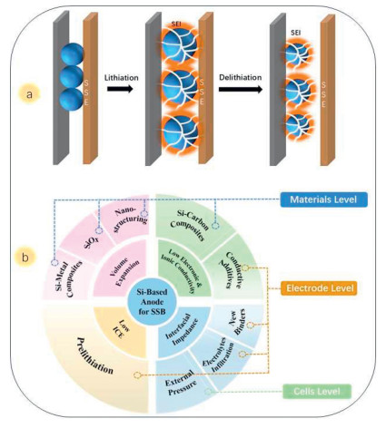
 DownLoad:
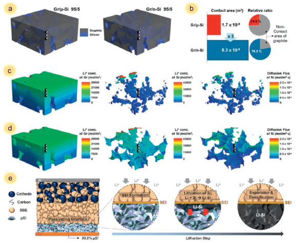
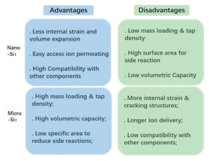
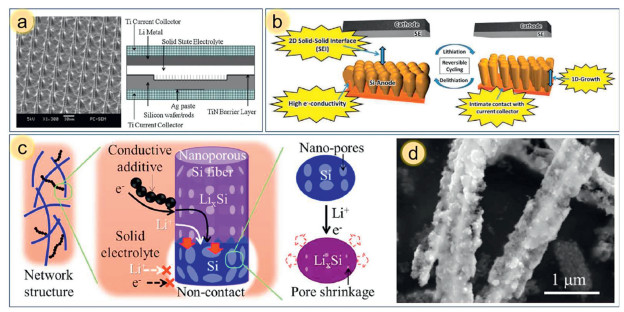
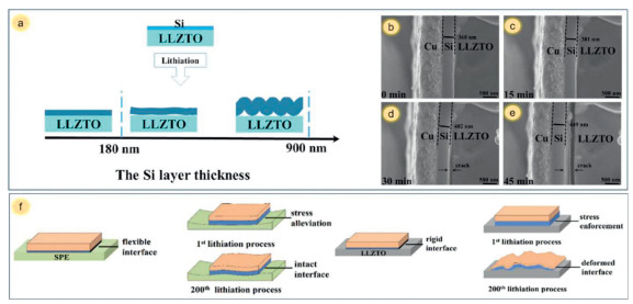
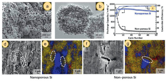
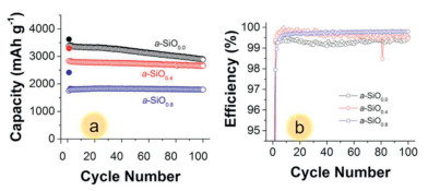
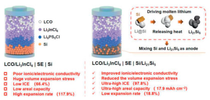
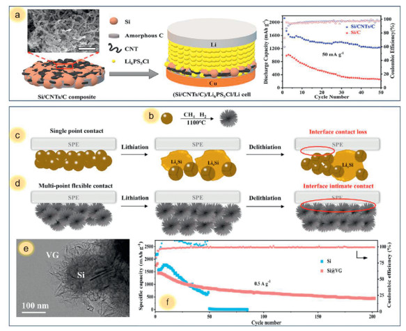
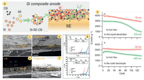
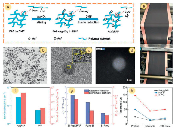
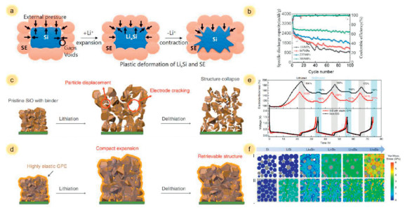
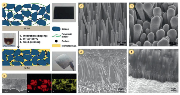

 下载:
下载:


 下载:
下载:
