Citation:
Song-Lin Tian, Li-Na Song, Li-Min Chang, Wan-Qiang Liu, De-Hui Guan, Ji-Jing Xu. A magnetic/thermal coupling assisted lithium-oxygen battery based on magnetic heating effect of single atom-Co/MoS2 cathode[J]. Chinese Chemical Letters,
2026, 37(8): 111349.
doi:
10.1016/j.cclet.2025.111349
A magnetic/thermal coupling assisted lithium-oxygen battery based on magnetic heating effect of single atom-Co/MoS2 cathode
English
A magnetic/thermal coupling assisted lithium-oxygen battery based on magnetic heating effect of single atom-Co/MoS2 cathode
School of Materials Science and Engineering, Changchun University of Science and Technology, Changchun 130012, China
b.
Key Laboratory of Preparation and Applications of Environmental Friendly Materials of the Ministry of Education, Jilin Normal University, Changchun 130103, China
c.
State Key Laboratory of Inorganic Synthesis and Preparative Chemistry, College of Chemistry, Jilin University, Changchun 130012, China
d.
International Center of Future Science, Jilin University, Changchun 130012, China
Received Date:
15 April 2025 Accepted Date:
19 May 2025 Revised Date:
14 May 2025 Available Online:
15 August 2026
Abstract:
Lithium−oxygen (Li−O2) batteries exhibit a superior energy density compared with any other battery currently available on the market. However, the practical application has been impeded by the insulated, insoluble discharge product (Li2O2). The limitations caused by Li2O2 are hardly to be addressed through the conventional catalyst design, which relies on the electronic structure and interfacial charge transfer characteristics. Herein, a magnetic/thermal coupling assisted Li−O2 batteries based on the thermoelectric material of MoS2 and magnetism single atom cobalt (SA−Co/MoS2) was constructed for the first time, by combing the magnetic heating and the thermoelectric catalytic effect. The spin polarization of the single atom Co may be promoted and a magnetic heating effect is generated by an external magnetic field, speeding up the oxygen evolution process (OER) and oxygen reduction reaction (ORR), as well as promoting the parallel spin arrangement of oxygen atoms. Because of its special SA−Co/MoS2 cathode, the Li−O2 battery with magnetic/thermal coupling assistance offers an ultra-low charging platform of 3.33 V and an ultra-high discharge platform of 2.90 V. The proposed novel method of sustaining the magnetic and thermal fields provides a crucial guidance for adjusting the excessive overpotential in metal−air battery systems.
Given the continuous use of fossil fuels like coal, oil, and natural gas, environmental pollution and other problems have been seriously aggravated. It is necessary to develop clean, efficient electrochemical energy storage technologies. Lithium-ion batteries are recognized as the commonly utilized energy storage system because of their high energy density (200 Wh/kg) [1–5]. However, the limited energy density of lithium−ion batteries is insufficient to meet the demands in some specific fields. Rechargeable lithium−oxygen (Li−O2) batteries are regarded as one of the most potential substitutes for electrochemical energy storage technologies because of their high theoretical energy density (3600 Wh/kg) compared with lithium−ion batteries [6–10]. Traditional Li−O2 batteries are operating based on the production and decomposition of solid Li2O2, corresponding to the oxygen evolution reaction (OER) and oxygen reduction reaction (ORR). Nonetheless, Li−O2 batteries still face a number of significant scientific challenges, such as the sluggish ORR and OER kinetics, caused by the inadequate conductivity of the discharge product Li2O2, leading to high overpotential as well as the reduced rate performance and poor cycling life. Solving the sluggish ORR and OER kinetics in the oxygen cathode is considered to be an effective way to improving the comprehensive performance of Li−O2 batteries.
To improve the ORR and OER kinetics in Li−O2 batteries, a diverse array of cathode catalysts has been systematically designed to enhance the decomposition of Li2O2, including carbon materials, transition metal oxides and sulfides, as well as noble metals [11–15]. The optimization and modification of these catalysts have been achieved through the defect engineering, heterogeneous structuring, and element doping to enable the precise regulation and functional enhancement of catalytic active sites. Nevertheless, challenges still existed for Li−O2 battery catalysts, including kinetic hysteresis associated with multiphase reactions and significant side reactions triggered by the highly reactive intermediate LiO2. Furthermore, the costly solid-phase catalysts and the solid-solid interface with electrode materials, leading to the diminished charge transfer efficiency. While advancements in cathode catalyst development for Li−O2 batteries is proceeding, several obstacles still exist—such as the sluggish kinetic related with multiphase reactions and serious side reactions instigated by the highly reactive intermediate LiO2 [16–20]. Therefore, it is necessary to develop more efficient, cathode for Li−O2 batteries.
Aside from the traditional solutions, the utilized outfield-assisted strategy is considered to be a successful method in developing highly-efficient cathode, among which the photo−assisted Li−O2 battery system has been widely studied. And a series of photocatalysts such as Fe2O3 [21], Au/rGO [22], Fe-UiO-66 [23], WO3/CC [24], FeNi-TCPP [25] have been developed. However, the introduction of light in the metal–air battery system is typically accompanied by accelerated lithium anode corrosion and electrolyte decomposition side reactions. Additionally, the consumption of the light source and the increased complexity of the equipment are not conducive to the application prospects of light-assisted Li−O2 batteries. Therefore, other out field-assisted strategies including Ag or Au-based optical/thermal coupling field-assisted, Bi0.5Na0.5TiO3 or MoS2/Pd-based force field-assisted metal–air batteries have been proposed by our group, demonstrating the effect of force fields and light fields on improving the dynamics of metal-air battery [26–29]. Inspired by the positive synergistic effect of the assisted force-light fields on the enhanced battery performance, the magnetic heating coupled field, which has not been adopted in rechargeable batteries, is expected to play a favorable role in developing high performance energy storage system.
Here, a Li−O2 battery supported by magnetic/thermal coupling field based on the combined thermoelectric catalytic effect and magnetic heating effect is presented using a magnetism single atom cobalt and thermoelectric material MoS2 (SA−Co/MoS2). Spin polarization is demonstrated to enhance the OER performance of magnetic catalysts when an external magnetic field is presented, which is ascribed to lowered kinetic barrier of the oxygen-oxygen bond originated from the spin polarization, encouraging the parallel spin arrangement of oxygen atoms to generate the triplet oxygen molecules. In addition, the parallel magnetic field is conducive to the uniform deposition of lithium anodes [30,31]. Additionally, during the discharge and charging processes of the magnetic/thermal coupling assisted Li−O2 battery, the amount of electron hole pairs generated in the SA−Co/MoS2 electrode significantly speeds up the synthesis and breakdown of Li2O2. For the Li−O2 battery, an ultra-low potential of 3.33 V while charging and an ultra-high potential of 2.90 V during discharging is reached. Thus, a novel coupled external field technology for metal-air batteries with an efficient energy conversion and storage capacity is provided by the magnetic/thermal coupling field assisted Li−O2 battery, which is based on the thermoelectric catalysis coupling effect and magnetic heating.
The magnetical/thermal coupling field assisted Li−O2 battery is built by combining the thermoelectric catalysis and magnetic heating effect with magnetism single atom cobalt and thermoelectric material MoS2 (SA−Co/MoS2) to speed up the kinetics of the OER and ORR by generating the electrons and holes when exposed to a magnetic field. The chemical process for oxygen evolution and reduction driven by SA−Co/MoS2 in a magnetic field is illustrated using a magnetothermal catalyst. SA−Co/MoS2 were synthesized using the subsequent two-step procedure: Firstly, a hydrothermal approach was used to create the precursor nanoparticles, followed by the subsequently calcination at high temperature under Ar gas. Based on the thermoelectric catalytic effects and magnetic heating of SA−Co/MoS2, a magnetoelectric engine is generated by producing thermal electrons and holes to catalyze the Li−O2 batteries without other energy supply. In particular, the application of thermoelectric catalysis in conjunction with the magnetic heating in battery systems is developed in an effective magnetothermal nano catalytic Li−O2 battery system.
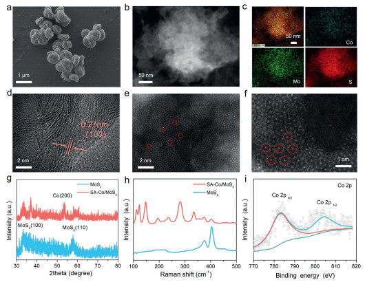
To speed up the ORR and OER kinetics by highly active catalyst for Li−O2 batteries, a magnetic single atom cobalt and thermoelectric material MoS2 cathode catalyst (SA−Co/MoS2) is constructed through a straightforward hydrothermal and calcination approach. As shown in the scanning electron microscope (SEM) images and the element mappings (Figs. S1 and S2 in Supporting information), the elements Mo and S were uniformly dispersed on MoS2. Additionally, the transmission electron microscopy images (TEM) reveal that the MoS2 nanospheres display a radius of approximately 250 nm (Fig. S3 in Supporting information). Based on the SEM (Fig. 1a) and TEM (Fig. 1b) results after the addition of the cobalt source, the obtained SA−Co/MoS2 nanospheres have a radius of around 500 nm. And Co, Mo, and S elements can be observed through the element mappings and energy spectrum of SA−Co/MoS2 (Fig. 1c and Fig. S4 in Supporting information). The lattice fringes for SA−Co/MoS2 have radial spacings of 0.27 nm, which match the (100) planes of MoS2 according to a transmission electron microscope (TEM) (Fig. 1d). The SA−Co/MoS2 structure was examined using the HAADF-STEM method to demonstrate the existence of individual cobalt atoms without any nanoparticles or cluster (Figs. 1e and f), which is also verified by the peak observation at 53.5° from the X-ray diffraction (XRD) pattern. Furthermore, the peaks in Fig. 1g at 32.6°, 39.5°, and 58.3° supported the coexistence of MoS2 (PDF #37-1492). The effective introduction of MoS2 is demonstrated by the Raman peaks at 375.7 and 403.4 cm−1, and the successful introduction of Co single atoms is demonstrated by the Raman peaks at 124.1, 147.8, 195.5, 235.1, 282.6, and 336.1 cm−1 (Fig. 1h). Furthermore, the Co signals are clearly observed from the XPS spectrum of the SA−Co/MoS2 cathode in Fig. 1i. The peaks in SA−Co/MoS2 at Co 2p3/2 (783.1 eV) and 3d1/2 (804.2 eV), and the peaks in the SA−Co/MoS2 sample at Mo 3d (238.6eV) and S 2p (167.5 eV) show the successful preparation of SA−Co/MoS2 (Fig. S5 in Supporting information). For SA−Co/MoS2, the cathode displays a specific area of about 23.93 m2/g (Fig. S6 in Supporting information). Thus, based on the magnetic heating and thermoelectric catalysis effect, the SA−Co/MoS2 magnetothermal nanoparticles is capable of serving as the highly effective cathode for Li−O2 battery based on the magnetic/thermal coupling effect.
Figure 1
Figure 1.
(a) SEM image of SA-Co/MoS2. (b) TEM image of SA-Co/MoS2. (c) TEM mapping image of SA-Co/MoS2. (d-f) HAADF-STEM images of SA-Co/MoS2. (g) XRD patterns of MoS2 and SA-Co/MoS2. (h) Raman patterns of MoS2 and SA-Co/MoS2. (i) XPS spectra of Co 2p.
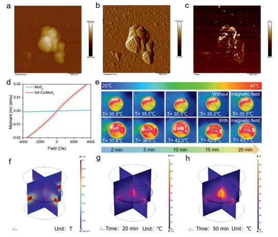
For SA−Co/MoS2, the dual coupling effects of thermoelectric catalysis and magnetic heating were confirmed according to the magnetic force microscope (MFM). To investigate their magnetic characteristics, the magnetic properties of SA−Co/MoS2 are firstly explored. More visible pits on the surfaces of the nanoparticle particles were observed in the MFM topography picture. In Figs. 2a-c, the uneven out-of-plane stripe illustrates the high magnetic properties of SA−Co/MoS2 nanoparticles. The domain distribution and surface magnetic area of nanoparticles are reflected in this striped contrast. Then, the magnetic saturation strength was determined using a vibrating sample magnetomete (VSM). The magnetic hysteresis curve (Fig. 2d), which shows a typical paramagnetism saturated with a magnetic field of 4000 Oe and a coercivity of 161.2 Oe, suggesting the convention of SA−Co/MoS2 to ferromagnetism with the assisted magnetic field [32]. In order to confirm if the presence of thermal effect for SA−Co/MoS2 is related with the magnetic field, the infrared thermal images are carried out. As shown in Fig. 2e, the infrared thermal images of SA−Co/MoS2 with and without magnetic field for 2, 5, 10, 15 and 20 min indicate the thermal effect generation is closely related with the magnetic field. A microscopic discussion of the magnetic heating impact in SA−Co/MoS2 nanoparticles was carried out with a magnetic field through a finite-element simulation (FEM) for MoS2 and SA−Co/MoS2 nanosphere. Owing to the magnetic heating effect of SA−Co/MoS2 nanosphere, magnetic flux density (Fig. 2f) and suitably generated thermal effect (Figs. 2g and h) were observed when exposed to a magnetic field. According to the previously modeling results, a local thermal effect could generate when SA−Co/MoS2 is subjected to a magnetic field in order to initiate the specific chemical reactions. When the magnetic heating effect for MoS2 nanosphere is absent, no magnetic flux density or thermal effects can be observed for the MoS2 nanosphere when SA−Co/MoS2 is subjected to a magnetic field. The aforementioned simulation findings show that there are no local thermal effects when a magnetic field is applied to molybdenum disulfide (Fig. S7 in Supporting information). Additionally, simulations were conducted to observe the temperature variations of MoS2 and SA−Co/MoS2 in response to a magnetic field over different time intervals. After 100 min, MoS2 exhibited minimal temperature change, whereas compared with an increased temperature of 16.3 ℃ for SA−Co/MoS2 (Figs. S8 and S9 in Supporting information). The above findings demonstrate the bidirectional conversion of magnetothermal field and the proceeded magnetothermal reaction.
Figure 2
Figure 2.
(a-c) Corresponding MFM height, amplitude and phase images of SA-Co/MoS2. (d) Magnetization reversal hysteresis loops of SA-Co/MoS2. (e) Infrared thermal imaging images of SA-Co/MoS2. COMSOL simulation for the temperature changes in SA-Co/MoS2. (f) Magnetic thermal distribution of SA-Co/MoS2. (g) Temperature of SA-Co/MoS2 at 20 min. (h) Temperature of SA-Co/MoS2 at 50 min.
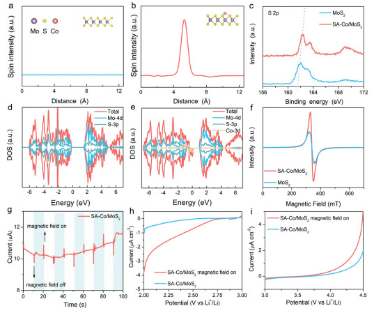
As demonstrated by the above-mentioned analysis, the application of an external magnetic field is capable of enhancing the spin polarization of individual cobalt atoms, leading to a magnetic heating effect, which is conducive to aligning the spins of oxygen atoms in parallel and accelerating the kinetics of both the OER and the ORR. The spin density patterns of MoS2 and SA−Co/MoS2 are shown in Figs. 3a and b, respectively. The symmetric spin charge concentrations between spin-up and spin-down can deduce that nonmagnetic MoS2 lacks a magnetic moment or overall spin states, but in ferromagnetic SA−Co/MoS2, the spin polarized states are primarily contained near Co single atoms, highlighting the significant role of Co single atoms on both the ferromagnetism generation and the magnetic field-assisted OER process of SA−Co/MoS2 [33]. The positive change of the S binding energy in SA−Co/MoS2 may be ascribed to the production of S vacancy, as suggested by the XPS spectra of S 2p in Fig. 3c, indicating the presence of electron-deficient MoS2, which can be explained by the charge redistribution between MoS2 and Co single atoms during their hybridization. According to the Spin-resolved density of states (DOS) calculations, the symmetrical spin down and spin up in the MoS2 total density of states (TDOS) indicates the nonmagnetism in this compound (Fig. 3d), which is consistent with the previous findings. Nonetheless, for SA−Co/MoS2, a pronounced imbalance in TDOS between the spin up and spin down near the Fermi level is observed (Fig. 3e). The results show that SA−Co/MoS2 containing anchored Co single atoms exhibits ferromagnetic properties originated from the exchange interactions between Co 2p, Mo 3d, and S 2p. To further prove the existence of Co single atoms and S vacancy, we carried out the electron paramagnetic resonance (EPR) analysis. An elevated symmetry signal in both MoS2 and SA−Co/MoS2 is observed in Fig. 3f, demonstrating more sulfur vacancies existed in SA−Co/MoS2. As shown in Fig. 3g, a clear magnetoelectricity current signal was obtained for the SA−Co/MoS2 cathode under magnetic field, However, the I-t curve of MoS2 without Co doping shows no current change with/without a magnetic field (Fig. S10 in Supporting information), further demonstrating that the thermal effect caused by the magnetic heating effect is conducive to enhancing the electric current responsiveness.
Figure 3
Figure 3.
(a) Plot of spin density distribution extracted along the MoS2 model in the top inset. (b) Plot of spin density distribution extracted along the SA-Co/MoS2 model in the top inset. (c) XPS spectra of S 2p. (d) DOS results of MoS2. (e) DOS results of SA-Co/MoS2. (f) The EPR spectra of MoS2 and SA-Co/MoS2. (g) Transient current responses of SA-Co/MoS2. (h) ORR and (i) OER process with/without magnetic field at a scan rate of 5 mV/s.
To explore whether the SA−Co/MoS2 cathode is suitable for Li−O2 battery, the band gap of SA−Co/MoS2 is further studied. The x-axis intercept from the Tauc curve according to the UV−vis absorption spectroscopy (Fig. S11 in Supporting information) shows the Eg value of SA−Co/MoS2 of 2.46 eV. Additionally, a positive slope trend in the Mott−Schottky plots represents an obvious an n-type semiconductor of SA−Co/MoS2 (Fig. S12 in Supporting information), suggesting the thermoelectricity-induced holes as the predominant charge carriers [34]. And the valence band (VB) potential of SA−Co/MoS2 is 5.13 V versus Li+/Li, while the conduction band (CB) is 2.62 V. The CB and VB locations of SA−Co/MoS2 (vs. Li+/Li) are schematically displayed in the inset of Fig. S13 (Supporting information). When SA−Co/MoS2 is excited with ultrasonic, electrons and holes are generated in SA−Co/MoS2. Because the CB position of 2.62 V for Li−O2 battery system is more negative than the normal redox potential of 2.96 V, O2 is prone to be reduced by the ultrasonically stimulated electrons through a thermoelectric catalytic process. Since the VB potential of 5.13 V is greater than the potential of the Li2O2/O2 standard electrode, Li2O2 might be directly oxidized to Li+ and O2 by the ultrasonic generated holes. During the charging process, the generated piezoelectric voltage on SA−Co/MoS2 would compensate for the charge voltage. Appropriate CB and VB locations guarantee the effectiveness of SA−Co/MoS2 as a piezoelectric electrode during the ORR and OER procedures.
The LSV results with an oxygen-saturated aprotic electrolyte in Figs. 3h and i are adopted to examine the detailed impact of the thermal energy produced by the magnetic field. When exposed to a magnetic field, SA−Co/MoS2 displays a greater current response than SA−Co/MoS2, indicating the extraordinary ORR activity under the assisted magnetic field (Fig. 3h). Moreover, the generated amount of the thermal electrons and holes is closely related to the improved dynamic kinetics, according to the Tafel slope calculated from LSV curves. In comparison with 118.4 mV/decade for the SA−Co/MoS2 without magnetic field, SA−Co/MoS2 with a magnetic field exhibits a reduced value (115.9 mV/decade) (Fig. S14a in Supporting information). A similar phenomenon was observed for the OER process in Fig. 3i: A much smaller overpotential (200.7 mV/decade) is observed for SA−Co/MoS2 with magnetic field than SA−Co/MoS2 without magnetic field (247.8 mV/decade), demonstrating the beneficial effect of magnetic field on the catalytic performance of the magnetic/thermal coupling-assisted Li−O2 batteries (Fig. S14b in Supporting information). Furthermore, the impact of varying magnetic field intensities on the OER process was examined (Fig. S15 in Supporting information). It was observed that an increased magnetic field strength is favorable to enhancing the efficiency of the OER process [35]. All these findings show that the SA−Co/MoS2 catalyst is favorable to enhancing the ORR and OER kinetics of Li−O2 battery through magnetic/thermal coupling-assisted magnetic heating linked thermoelectric catalysis.
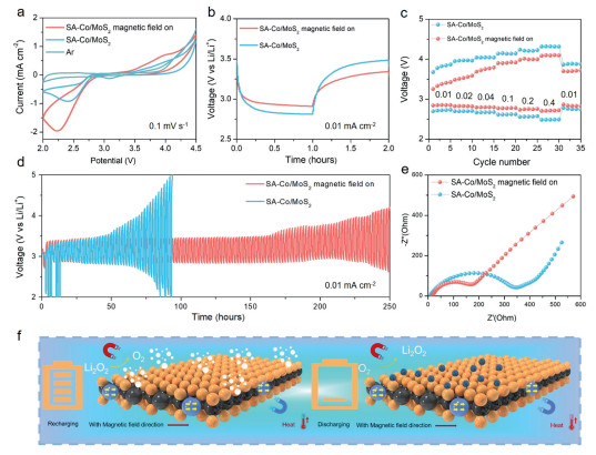
To investigate the effects of thermoelectric catalytic coupling and magnetic heating on batteries, a magnetic/thermal coupling assisted Li−O2 battery with SA−Co/MoS2 as the reversible magnetoelectric nanoparticles cathode was constructed. Cyclic voltammogram (CV) curves in the potential range of 2−4.5V (against Li+/Li) were used to study the catalytic performance of Li−O2 batteries with/without magnetic field (Fig. 4a). Furthermore, the significantly higher double-layer capacitance of SA−Co/MoS2 is observed under the assisted magnetic field than that without magnetic field (Fig. S16 in Supporting information), indicating that the rapid charge transfer and magnetic conversion efficiency are crucial to the enhanced catalytic OER and ORR kinetics through magnetic/thermal coupling [36]. Moreover, the thermoelectric catalytic coupling and magnetic heating inhibitory effects of SA−Co/MoS2 cathode lead to the rapidly decreased charge voltage from 3.47 V to 3.33 V and the dramatically increased discharge voltage from 2.80 V to 2.90 V under a magnetic field (Fig. 4b). The lower equilibrium potential under magnetic field than that without the magnetic field further demonstrate the positive effect of thermoelectric catalytic coupling effect and magnetic heating on enhancing ion conduction. The Li−O2 battery still displays the anticipated low charge voltage with magnetic field even at a high current density of 0.4 mA/cm2. When it reaches 0.01 mA/cm2, it may be recharged to 3.71 V after 30 cycles at various current densities (Fig. 4c). In contrast to the battery without a magnetic field, the battery after 80 h is dead, it is demonstrated the long-term cycle performance at 0.01 mA/cm2 with exceptional stability at an ultra-low charging platform of 4.17 V and an ultra-high discharging platform of 2.64 V after 250 h in a magnetic field (Fig. 4d). To deeply study on how magnetic/thermal coupling improved battery kinetics and Li ion diffusion, the EIS findings of Li–O2 battery were analyzed with and without magnetic field, at different magnetic field strengths (Fig. 4e and Fig. S17 in Supporting information). Li+ diffusion in the magnetic/thermal coupling assisted Li–O2 battery displays favorable interfacial charge transfer kinetics, suggesting a greater diffusion rate compared with that without the magnetic field.
Figure 4
Figure 4.
(a) CV curves of SA-Co/MoS2-based Li−O2 batteries with and without magnetic field at a scan rate of 0.1 mV/s. (b) Discharge and charge curves of Li−O2 battery for SA-Co/MoS2 cathode with/without magnetic field at 0.01 mA/cm2. (c) Rate performance of SA-Co/MoS2-based Li−O2 batteries with and without magnetic field. (d) Cycling performance of SA-Co/MoS2 with/without magnetic field. (e) The electrochemical impedance spectra of SA-Co/MoS2-based Li−O2 batteries with and without magnetic field. (f) Illustration of the magnetic-field assisted Li−O2 battery based on magnetic heating effect.
Different from the traditional Li−O2 battery, the magnetic/thermal coupling assisted Li−O2 battery is performed based on thermoelectric catalysis and magnetic heating, in which a thermoelectric composite SA−Co/MoS2 cathode and a magnetic single atom is adopted, and the magnetic single atom is capable of generating magnetic thermal energy under magnetic field (Fig. 4f). The conduction band (CB) and valence band (VB) of SA−Co/MoS2 cathode can separate magnetic thermal electrons and holes with the assisted magnetic field, accelerating the ORR and OER during the discharge and charge processes, respectively. Therefore, the appropriate energy levels of the CB and VB, corresponding to the ORR and OER abilities, are crucial to include magnetic field into the magnetic/thermal coupling assisted Li−O2 battery based on magnetic heating and thermoelectric catalytic coupling effects [37]. Consequently, by introducing a magnetic field to be stored in the magnetic/thermal coupling assisted Li−O2 battery based on magnetic heating and thermoelectric catalytic coupling effects, it is favorable to achieving the magnetic field conversion and improving the redox behavior of oxygen significantly throughout the cycle. The aforementioned findings proved that the SA−Co/MoS2 magnetoelectric nanoparticle structure-based Li−O2 battery with the assistance of the magnetic/thermal coupling effect is suitable for achieving reversible Li−O2 battery technology.
Furthermore, it is discovered that the unique discharge mechanism of Li−O2 batteries enables the effective regulation of the shape and deposition behavior of the discharge products Li2O2, as well as the enhanced catalytic performance in the presence of a magnetic field. Following discharge, the SEM images of SA−Co/MoS2 cathodes with and without a magnetic field are displayed in Figs. S18 and S19 (Supporting information). As shown in Fig. S18, the disc-shaped discharge products were randomly accumulated on the carbon paper without magnetic field, and the large products would coat on the surface of catalyst to prevent the electrolyte from the contact with the active sites, seriously hindering the followed electrochemical processes. However, when a magnetic field was added, the evenly distributed spherical-shaped products were observed throughout the current collector (Fig. S19 in Supporting information), and the active sites were well-exposed during the discharging process, ensuring the subsequent electrochemical reaction [38]. Simultaneously, the results of the discharged/charged SA−Co/MoS2 cathode with/without magnetic field, as well as the FT-IR spectra (Fig. S20 in Supporting information) and XRD patterns (Fig. S21 in Supporting information), demonstrate that the magnetic/thermal coupling field is favorable to adjusting the Li2O2 morphology. The XPS spectra of the discharged SA−Co/MoS2 displays the generated discharge product of Li2O2. The magnetic/thermal coupling-assisted Li−O2 battery is capable of adjusting the shape of discharge product Li2O2 and prevent the generation of the by-product Li2CO3. Furthermore, much less Li2CO3 is observed for the SA−Co/MoS2 cathode with magnetic field than that without magnetic field. Additionally, the peaks at 531.4, 55.1 eV in the XPS spectra correspond to Li 1s, O 1s, respectively (Figs. S22 and S23 in Supporting information). According to the abovementioned characterization of the discharge product Li2O2, it is demonstrated that the magnetic field-assisted Li−O2 battery is capable of suppressing the generation of the by-product Li2CO3 while accelerating the formation and decomposition of discharge product.
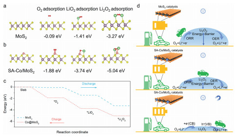
To investigate the in-depth O2 reduction/evolution processes during discharging/charging at SA−Co/MoS2 and MoS2 cathodes, density functional theory (DFT) calculations were further carried out (Figs. 5a and b). To achieve favorable O2 reduction, O2 molecules were firstly adsorbed on the cathode surface, where they can combine with Li ions to form LiO2 and accepted electrons. The reduction processes may be classified into two patterns based on the adsorption energy of O2 at SA−Co/MoS2 cathode surfaces: Those with and without ultrasonic channels. Furthermore, much negative formation energy of O2 and LiO2 species (-1.88, -3.47 eV) are detected in comparison with that of without magnetic/thermal coupling effect (-0.09, -1.41 eV), suggesting that the thermodynamically beneficial nucleation of O2 and LiO2 in solutions for the magnetic/thermal coupling assisted Li−O2 battery Ultimately, the discharge products mediated by the solution would aggregate into particles, and then deposited onto the surface of cathode. During the charging procedure, the differential charge density showed that there was no discernible charge transfer between the SA−Co/MoS2 cathode and Li2O2, demonstrating the specific magnetic/thermal connection effect on improving the charging kinetics (Fig. 5c) [39]. Fig. 5d clearly illustrates the performance potentials of various SA−Co/MoS2 and MoS2 catalysts. Due to its enriched defect sites, appropriate CB/VB value, higher O2 and weaker LiO2 adsorption strengths, and other characteristics, SA−Co/MoS2 is superior to MoS2 and other catalysts in Li−O2 batteries in terms of electricity savings and rate performances, pushing Li−O2 batteries toward record-high performances.
Figure 5
Figure 5.
(a, b) The structural model of MoS2 and SA-Co/MoS2 towards O2, and LiO2 adsorption, in which the purple balls, yellow balls, pink balls, red balls, and green balls represented Mo, S, Co, O and Li, respectively. (c) The reaction coordinate energy. (d) Illustration of the charge and discharge mechanism of MoS2 and SA-Co/MoS2 cathode with/without magnetic field in Li−O2 batteries.
In conclusion, by adopting the magnetic/thermal coupled field, a functional cathode catalyst of thermoelectric MoS2 (SA−Co/MoS2) and magnetism single atom cobalt for Li−O2 batteries is constructed. The catalytic performance of SA−Co/MoS2 can be largely enhanced based on an internal electric field mechanism, when subject it to an external magnetic field for thermoelectric catalysis and magnetic heating, the spin polarization of Co single atoms can be encouraged. Benefiting from the resulting magnetic heating effect, the parallel spin arrangement of oxygen atoms would further promote the kinetics of the OER and ORR. Based on this special SA−Co/MoS2 cathode, the magnetic/thermal coupling assisted Li−O2 battery displays an ultra-low charging platform of 3.33 V and an ultra-high discharge platform of 2.9 V. The finite element simulation and theoretical calculation further demonstrate the thermal effect with magnetic field. The combined magnetic heating effect in lithium-air batteries is favorable to achieving a highly effective, practical energy conversion and storage technology, providing a promising strategy to develop highly efficient metal-air batteries by utilizing the multi-field coupling effect.
Declaration of competing interest
The authors declare that they have no known competing financial interests or personal relationships that could have appeared to influence the work reported in this paper.
CRediT authorship contribution statement
Song-Lin Tian: Writing – original draft, Formal analysis, Data curation. Li-Na Song: Methodology, Investigation, Data curation. Li-Min Chang: Software, Methodology, Investigation. Wan-Qiang Liu: Project administration, Methodology, Data curation. De-Hui Guan: Investigation, Formal analysis, Data curation. Ji-Jing Xu: Writing – review & editing, Project administration, Funding acquisition.
Acknowledgments
This work was financially supported by the National Natural Science Foundation of China (Nos. 22425902, 22309166, 22409069), the 111 Project (No. B17020), the China Postdoctoral Science Foundation (Nos. 2024M751079, 2024T170336), the Postdoctoral Fellowship Program of CPSF (No. GZC20230932), the 2022-5 open project fund of the State Key Laboratory of Inorganic Synthesis and Preparative Chemistry (Jilin University), and the Fundamental Research Funds for the Central Universities.
Supplementary materials
Supplementary material associated with this article can be found, in the online version, at doi:10.1016/j.cclet.2025.111349.
[1]
J.M. Tarascon, M. Armand, Nature 414 (2001) 359-367. doi: 10.1038/35104644
M. Li, X. Wang, F. Li, et al., Adv. Mater. 32 (2020) 1907098. doi: 10.1002/adma.201907098
[35]
Y. Ma, Y. Zhou, C. Wang, et al., Adv. Mater. 35 (2023) 2303741. doi: 10.1002/adma.202303741
[36]
Z. Sun, L. Lin, J. He, et al., J. Am. Chem. Soc. 144 (2022) 8204-8213. doi: 10.1021/jacs.2c01153
[37]
H. Zhan, Z. Jiang, X. Luo, et al., Adv. Funct. Mater. 34 (2024) 2407660.
[38]
E. Zhang, A. Dong, K. Yin, et al., J. Am. Chem. Soc. 146 (2024) 2339-2344. doi: 10.1021/jacs.3c12734
[39]
J. Xia, S. Yin, K. Cui, et al., ACS Nano 18 (2024) 10902-10911. doi: 10.1021/acsnano.4c01271
Figure 1
(a) SEM image of SA-Co/MoS2. (b) TEM image of SA-Co/MoS2. (c) TEM mapping image of SA-Co/MoS2. (d-f) HAADF-STEM images of SA-Co/MoS2. (g) XRD patterns of MoS2 and SA-Co/MoS2. (h) Raman patterns of MoS2 and SA-Co/MoS2. (i) XPS spectra of Co 2p.
Figure 2
(a-c) Corresponding MFM height, amplitude and phase images of SA-Co/MoS2. (d) Magnetization reversal hysteresis loops of SA-Co/MoS2. (e) Infrared thermal imaging images of SA-Co/MoS2. COMSOL simulation for the temperature changes in SA-Co/MoS2. (f) Magnetic thermal distribution of SA-Co/MoS2. (g) Temperature of SA-Co/MoS2 at 20 min. (h) Temperature of SA-Co/MoS2 at 50 min.
Figure 3
(a) Plot of spin density distribution extracted along the MoS2 model in the top inset. (b) Plot of spin density distribution extracted along the SA-Co/MoS2 model in the top inset. (c) XPS spectra of S 2p. (d) DOS results of MoS2. (e) DOS results of SA-Co/MoS2. (f) The EPR spectra of MoS2 and SA-Co/MoS2. (g) Transient current responses of SA-Co/MoS2. (h) ORR and (i) OER process with/without magnetic field at a scan rate of 5 mV/s.
Figure 4
(a) CV curves of SA-Co/MoS2-based Li−O2 batteries with and without magnetic field at a scan rate of 0.1 mV/s. (b) Discharge and charge curves of Li−O2 battery for SA-Co/MoS2 cathode with/without magnetic field at 0.01 mA/cm2. (c) Rate performance of SA-Co/MoS2-based Li−O2 batteries with and without magnetic field. (d) Cycling performance of SA-Co/MoS2 with/without magnetic field. (e) The electrochemical impedance spectra of SA-Co/MoS2-based Li−O2 batteries with and without magnetic field. (f) Illustration of the magnetic-field assisted Li−O2 battery based on magnetic heating effect.
Figure 5
(a, b) The structural model of MoS2 and SA-Co/MoS2 towards O2, and LiO2 adsorption, in which the purple balls, yellow balls, pink balls, red balls, and green balls represented Mo, S, Co, O and Li, respectively. (c) The reaction coordinate energy. (d) Illustration of the charge and discharge mechanism of MoS2 and SA-Co/MoS2 cathode with/without magnetic field in Li−O2 batteries.


 DownLoad:

 下载:
下载:


 下载:
下载:

